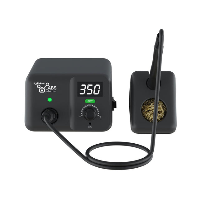
Soldeerstation voor precisiesolderen met actief verwarmde soldeerstift
Het AE970D soldeerstation is een krachtig 80 W apparaat om te kunnen solderen met een snelle opwarming. Het brede temperatuurbereik van 150-550°C zorgt ervoor dat hij aan al uw soldeerwensen kan voldoen. Dankzij de krachtige plug-and-play geïntegreerde actieve soldeerstift kan de AE970D binnen 9 seconden het smeltpunt bereiken. Gepatenteerde close-loop automatische en constante temperatuurregeling zorgt ervoor dat er gesoldeerd kan worden met veel stabiliteit, uitstekende prestaties en een hoge nauwkeurigheid.
Kenmerken
Een vermogen van 80 W voor een snelle opwarming.
Breed temperatuurbereik van 150-550°C (302-1022°F) om aan al uw soldeerwensen te kunnen voldoen.
Hoogwaardige plug-and-play geïntegreerde actieve soldeerstift, kan het smeltpunt binnen 9 seconden bereiken.
Gepatenteerde close-loop automatische en constante temperatuurregeling, wat veel stabiliteit, uitstekende prestaties en een hoge nauwkeurigheid garandeert.
Specificaties
Vermogen
80 W
Voedingsspanning
110 VAC / 230 VAC
Uitgangsspanning
25 VAC
Temperatuurbereik
150-550°C (302-1022°F)
Verwarmingselement
Geïntegreerde actieve verwarming uit de T80-serie
Temperatuurstabiliteit
±1°C/±1.8°F (bij temperatuur > 200°C/400°F)
Weerstand van stift naar aarde
< 2 Ω
Spanning van stift naar aarde
< 2 mV
Lengte netsnoer
1 m
Kabellengte naar soldeerbout
1,2 m
Afmetingen
148 x 120 x 85 mm
Gewicht (basis unit)
1,33 kg
Inbegrepen
Basis unit
Soldeerbout incl. soldeerstift T80-D12
IJzeren standaard
Messing wolbedje
Handleiding
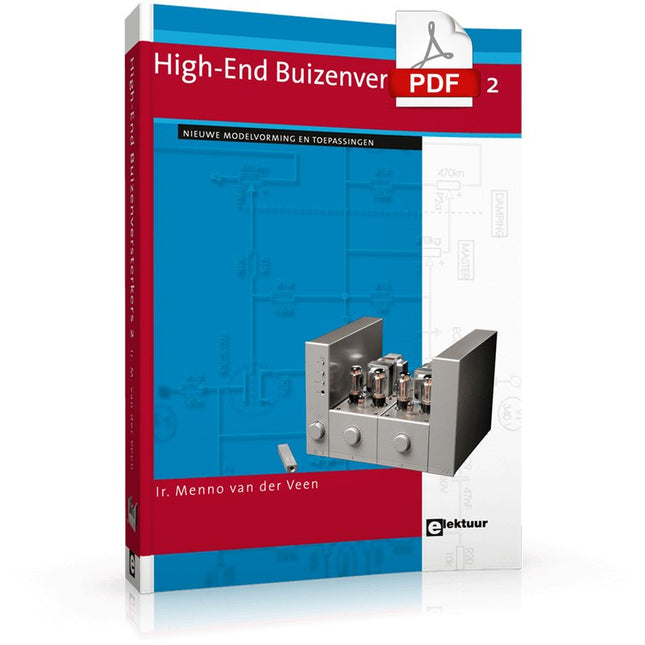
Niemand twijfelt er aan dat buizenversterkers een opmerkelijk mooi geluid produceren. Ze klinken levendig, diep en doortekend; het klankbeeld is zeer aangenaam en dynamisch schijnen ze nagenoeg geen beperkingen te kennen.Via een systematisch theoretisch onderzoek gaat de auteur na waardoor deze fraaie eigenschappen ontstaan. Hij ontwikkelt nieuwe modellen voor versterkerbuizen en transformatoren, waardoor het mogelijk wordt om op voorhand, tijdens het ontwerp, al te bepalen wat de eigenschappen van de buizenversterker worden. De koppeling tussen eindbuizen en de uitgangstransformator wordt diepgaand gemodelleerd. Daarbij ontstaan nieuwe inzichten in een uitzonderlijk soort vervorming: de dynamische dempingsfactor vervorming (DDFD).
Via rekenmodellen in het complexe domein worden vooral de eigenschappen in de grenzen van het hoorbare gebied (tussen 20 Hz en 20 kHz) onderzocht en ontstaan stabiliteitsvoorwaarden waar de versterker minstens aan moet voldoen. In versterkers wordt vaak tegenkoppeling toegepast, die uitgebreid wordt gemodelleerd en waarvan de gehoorsmatige gevolgen diepgaand worden besproken.Vervolgens wordt een fraaie selectie van bijzondere buizenversterkers besproken.
Kenmerkend in dit boek is dat de auteur niet alleen technisch schrijft, maar verhalend laat zien dat het ontwikkelen van buizenversterkers ook ingrijpt in je dagelijkse leven; zelfs het nut van patenten wordt besproken. Samenvattend: nieuwe theorieën en oplossingen voor een perfecte audiokwaliteit met buizenversterkers. Zowel de zelfbouwer als diegene die kennis en inzicht wil verwerven zal dit boek met plezier ter hand nemen.
The Seeed Studio RF Explorer WSUB1G+ is a powerful, high-performance digital spectrum analyzer covering frequencies from 50 kHz to 1 GHz. The Slim model features a robust design, a more conveniently positioned USB connector on the side, and a larger internal battery capacity.
Kenmerken
Internal LNA amplifier and selectable attenuator
Low frequency support from 50 KHz covering LF, MF, HF, VHF and UHF up to 960 Mhz
New HELP and SET buttons to improve user interface and configuration selection with 2-clicks
Wide band coverage to all popular sub-1 Ghz bands, including FM, TV and DTV, ISM, RFID, GSM, etc.
Ideal choice for HAM bands from 160 m to 33 cm
Pocket size and light weight
Solid metal case
Spectrum Analyzer mode with Peak Max and Hold, Normal, Overwrite and Averaging modes
High capacity internal Lithium battery for 20hs+ of continuous run, rechargeable by USB
Multi-platform Windows/Linux/MacOS Open Source software and API libraries
Can be extended with internal Expansion Modules for additional band and functionality
Specificaties
Frequency band: 0.05 MHz – 960 MHz
Frequency span: 0.1 MHz – 960 MHz
Internal selectable LNA 25 dB gain
Internal selectable Attenuator 30 dB
Graphics LCD 128 x 64 pixels, great visibility outdoors
Support included for Windows, Linux and MacOS X
Backlight for great visibility indoor
Internal Lithium Ion 1800 mA/h rechargeable battery
Standard SMA 50 Ω connector
Wideband 144/433 MHz dual band telescopic antenna included
UHF 400-900 MHz rubber duck articulated antenna included
Amplitude resolution: 0.5 dBm
Dynamic range: -125 dBm to 10 dBm
Absolute Max input power: +30 dBm
Average noise level (typical LNA): -125 dBm
Frequency stability and accuracy (typical): ±10 ppm
Amplitude stability and accuracy (typical): ±2 dBm
Frequency resolution: 1 kHz
Resolution bandwidth (RBW): Automatic 2.6 kHz to 600 kHz
Inbegrepen
1x Seeed Studio RF Explorer WSUB1G+ Slim Spectrum Analyzer
1x Mini USB cable
1x Dual band 144/430 MHz Telescopic antenna
1x UHF 400-900 Mhz antenna
1x EVA case
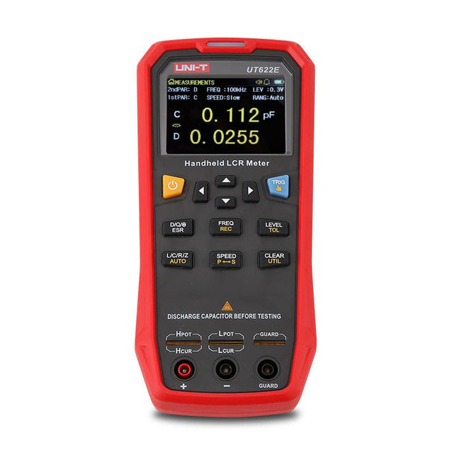
The UT622E handheld LCR meter features powerful functions, high accuracy, fast speed, and long standby time. With a clear and intuitive 2.8-inch TFT LCD display, large-capacity rechargeable battery, and 100 kHz test frequency, the meter can be used for longstanding accurate and convenient measurement in any occasion.
It is suitable for the measurement and screening of inductance, capacitance, and resistance in laboratories, production lines, maintenance points, etc.
Features
Max. test frequency: 100 kHz
Accuracy: 0.1%
Display count: 99999
Max. test rate: 20 times/s
DCR: Yes
Connectivity: Mini-USB
Display: 2.8" TFT LCD
Specifications
Testfrequency
100 Hz, 120 Hz, 1 kHz, 10 kHz, 100 kHz
Test level
0.1 Vmrs, 0.3 Vrms, 1 Vrms
Output impedance
100 Ω
Measurement parameters
Primary: L/C/R/Z/DCRSecondary: D/Q/Θ/ESR
DSR speed test
Fast (20 times/s), medium (5 times/s), or slow (2 times/s)
Range
Auto/Hold
Tolerance range
1%~20%
Equivalent mode
Series/Parallel
Clearing connection
Open/Short circuit
Fuse of test ports
0.1 A/250 V
Communication interface
Mini-USB
MAX reading of primary parameters
99999
MIN resolution
0.0001
Maximum accuracy
0.10%
L
0.00 µH~99.999 H
C
0.00 pF~99.999 mF
Z/R
0.0000 Ω~9.9999 MΩ
ESR
0.0000 Ω~999.99 Ω
D
0.0000~9.9999
Q
0.0000~99999
Θ
-179.9°~179.9°
DCR
0.01 mΩ~20.000 MΩ
Power supply
3.7 V/1800 mAh lithium polymer battery
Display
2.8" TFT LCD (320x240)
Dimensions
93 x 192 x 44 mm
Weight
420 g
Included
UT622E LCR meter
Short circuit board
Four-terminal kelvin test leads
USB cable
Manual
Downloads
Datasheet
Manual
Software
De MDP-P906 heeft een ingebouwde ventilator en een maximaal uitgangsvermogen van 300 W, wat toereikend is voor een breed scala aan testbehoeften en toepassingen. Via 2,4 GHz draadloze communicatie kan hij worden aangesloten op de MDP-M01 Smart Digital Monitor module om daarmee een flexibele combinatie van meerdere kanalen van 300 W per kanaal te kunnen realiseren. De MDP-P906 heeft een basis, stabiliteit en betrouwbaarheid die te vergelijken is met een professionele voeding. Hij kan puur stroom leveren én krachtige functies hieraan toevoegen, zoals programmeerbare uitgang, getimede uitgang, getimede regeling, automatische compensatie, boost modus, enz. Dit maakt hem tot een kosteneffectieve, slimme en op maat programmeerbare lineaire DC-voeding. De MDP-P906 heeft een zorgvuldig CNC-gefreesde aluminium behuizing, met verfijnde afwerking, eigentijds, bescheiden en prachtig uiterlijk. Hij wijkt hiermee volledig af van het standaard uiterlijk van een traditionele desktop voeding. Door een stackable modulair ontwerp en de draadloze communicatie kan de MDP-P906 onafhankelijk of onderling gekoppeld worden gebruikt, zowel in de normale werkruimte als bij onderhoud op locatie. De MDP-P906 is een perfecte oplossing voor elektrotechnici, met name servicemonteurs, om bij verschillende situaties en toepassingen de stroom te leveren. Ingebouwde stille ventilator, instant cooling, voor een stabiele en efficiënte output! Slimme lineaire compensatie, constante spanning & constante stroom Positieve en negatieve output, series boost, parallelle stroomverdeling Toepassingen Universele tests en onderwijsexperimenten in R&D laboratoria Onderhoud van digitale producten Eigendomsverificatie en foutdiagnose van apparaten en circuits Noodstroomvoorziening voor modelvliegtuigen en voertuigen Voedingen testen van RF en microgolfcircuits of -modules Kwaliteitscontrole en kwaliteitsinspectie Zuivere voeding voor zeer nauwkeurige digitaal-analoge hybride circuits en Hi-Fi audioapparaten Specificaties Input DC 4.2-30 V / 14 A (Max)QC 3.0/PD2.0, 20 V / 5 A (Max) Uitgang 0-30 V / 0-10 A, 300 W (Max) Conversie efficiëntie 95% Output resolutie 10 mV / 2 mA, tot 1 mV / 1 mA via Display Control module Output nauwkeurigheid 0,03%+5 mV0,05%+2 mV Adjustment rate Load adjustment rate <±0,01%Power adjustment rate <±0,01% Ripple en noise <250 uVrms, 3 mVpp; 2 mArms Transient response <4 uS Beveiligingen Te hoge voedingsspanning, onderspanning, omgekeerd aansluiten, te hoge uitgangsstroom, retourstroom en oververhitting Overig Automatisch afsluiten en naar micro-power modeOndersteuning van USB firmware upgrade Afmetingen 112 x 66 x 20 mm Gewicht 181 g Inbegrepen 1x MDP-P906 digitale voeding 2x uitgangskabel 1x gebruikershandleiding Downloads User Manual v1.1 Firmware v1.32
Für den sensiblen und kritischen HiFi-Hörer ist die Röhrenverstärkung noch immer der "musikalischste" Weg der Signalaufbereitung in der Übertragungskette Signalquelle, Verstärker und Lautsprecher. Transparenz, Räumlichkeit, Tiefe, Klangfülle, Wärme... alle diese oder ähnliche Charakterisierungen versuchen etwas zu umschreiben, was kaum zu beschreiben ist, bei dem die Sprache scheinbar "versagt": das Hörerlebnis "Röhre".
Moderne Audio-Röhren-Spitzengeräte sind im Schnitt sündhaft teuer; bei den niedrigen, ausschließlich in Handarbeit gefertigten Stückzahlen ist das erklärlich. Schaltungstechnisch gibt es bei den Röhrenverstärkern kaum mehr Geheimnisse, denn die Röhrentechnologie wurde bereits vor rund 30 Jahren "erwachsen". Allenfalls die Herstellung hochwertiger Ausgangsübertrager wird teilweise als gut gehütetes Fabrikationsgeheimnis behandelt.
Was für den Audio-Hörer gilt, gilt auch für die meisten – nicht nur technisch interessierten – Gitarrenspieler allemal: für sie produziert die Röhre "the singing voice", die das Gitarrenspiel erst lebendig erscheinen lässt.
Dieses Buch macht alle diese Dinge dem technisch interessierten Leser deutlich. Es zeigt dem praxisorientierten Audio-Hörer und Musiker Alternativen auf, wie man durch Selbstbau zu einem preiswerten Röhren-Equipment kommen kann. Dazu gehört, dass auch einige theoretische Zusammenhänge nicht ganz aus dem Blickfeld geraten.
De OWON SDS1102 is een betaalbare benchtop digitale oscilloscoop die solide prestaties combineert met essentiële meetfuncties. Deze 2-kanaals oscilloscoop biedt een bandbreedte van 100 MHz, een sample rate van 1 GS/s, een 7-inch LCD-display en een geheugendiepte van 10 kpts. Daarmee is het een praktische keuze voor dagelijkse elektronicatests, foutopsporing en onderwijs.
De SDS1102 beschikt over een vereenvoudigd triggersysteem met niveau- en flanktriggering, waardoor gangbare signalen eenvoudig kunnen worden vastgelegd en geanalyseerd. Het apparaat is ontworpen voor toepassingen waarvoor geen grote geheugendiepte of geavanceerde triggerfuncties nodig zijn, en biedt een eenvoudige en kostenefficiënte oplossing voor basis-signaalanalyse.
Kenmerken
Bandbreedte: 100 MHz
2 kanalen
Bemonsteringssnelheid: 1 GS/s
Ultradunne behuizing
7-inch lcd met hoge resolutie
Ondersteuning voor SCPI en LabVIEW
Specificaties
Bandbreedte
100 MHz
Horizontale schaal (s/div)
5 ns/div - 1000 s/div
Kanalen
2
Verticale gevoeligheid
5 mV/div - 5 V/div (bij ingang)
DC Gain nauwkeurigheid
3%
Verticale resolutie (A/D)
8 bits (2 kanalen tegelijk)
Ingang
Ingangsimpedantie
1 MΩ, 10 pF
Ingangskoppeling
AC, DC, GND
Max ingangsspanning
± 400 V, CATI, CATII
Passieve probes
x1; 10
Probe verzwakkingsfactor
x1; x10; x100; x1000
Triggersysteem
Trigger mode
Auto, Normal, Single
Trigger type
Flank, Video
Flank triggerbron
CH1, CH2
Video trigger
Sampletype
Real-time
Samplefrequentie
1 GS/s
Equivalente samplesnelheid
No
Golflengte
10K pts
Interpolatie
sin(x)/x
Meet- en rekenkundig bewerkingssysteem
Automatische meting
Vpp, Vavg, RMS, Frequency, Period, Vmax, Vmin, Vtop, Vbase, Width, Overshoot, Pre-shoot Rise time, Fall time, +Width, -Width, +Duty, -Duty, Delay A->B, Delay A->B, area, cycle area
Rekenkundige functies
Addition, Subtraction, Multiplication, Division, FFT
Algemene kenmerken
Display maat
7" color LCD
Display resolutie
800 x 480
Voeding
100-240 V, 45-440 Hz, <15 W
Afmetingen
301 x 70 x 152 mm
Gewicht
1,1 kg
Inbegrepen
1x OWON SDS1102 Oscilloscoop
2x Oscilloscoopsonde
1x Sonde aanpassen
1x Netsnoer
1x USB-kabel
1x CD-Rom
1x Snelstartgids
Downloads
Quick Guide
Manual
PC Software
SCPI Commands
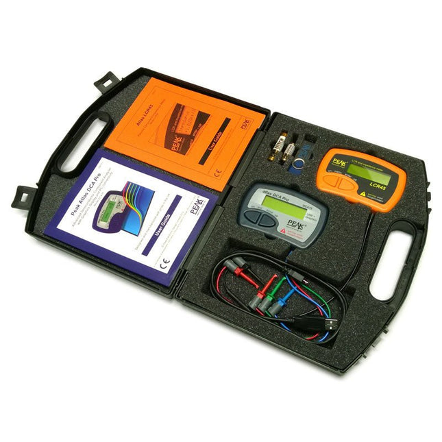
This pack contains the LCR45 Passive Component Impedance Meter, great for advanced hobbyists and professionals. It also contains the very popular DCA Pro (model DCA75), fantastic for component identification, pinout identification, detailed characteristic measurement and curve tracing on a PC. Complete with USB cable and software on a USB flash drive.
DCA75
Building on the continued success of Peak's existing component identification and analysis instruments, the DCA Pro brings an array of exciting new features for the hobbyist and professional alike.
The DCA Pro is an advanced new design that features a graphics display, USB communications, PC Software and an enhanced component identification library.
Automatic component type identification
Automatic pinout identification (connect any way round)
The DCA Pro supports all the components that the popular Peak Atlas DCA55 supports, but adds plenty more. Components supported include:
Transistors (including Darlingtons), Silicon and Germanium types. Measures gain, Vbe and leakage
MOSFETs, enhancement mode and depletion mode types. Measure on-threshold (at 5 mA) and approx transconductance (for span of 3-5 mA)
JFETs, including normally off SiC types. Measures pinch-off voltage (at 1 uA) and approx transconductance (for span of 3-5 mA)
IGBTs (insulated gate bipolar transistors). Measures on-threshold (at 5 mA)
Diodes and Diode networks
LEDs and bicolour LEDs (2 lead and 3 lead types)
Zener Diodes with measurement of zener voltage up to 9 V at 5 mA
Voltage regulators (measures regulation voltage, drop-out voltage, quiescent current)
Triacs and Thyristors that require less than 10 mA of gate current and holding current
Stand-alone or with a PC
The instrument can be used stand-alone or connected to a PC. Either way, the DCA Pro will automatically identify the component type, identify the pinout and also measure a range of component parameters such as transistor gain, leakage, MOSFET and IGBT threshold voltages, pn characteristics and much more.
Curve Tracing
When connected to a PC using the supplied USB cable, a range of low current curve-tracing functions can be performed. Various graph types are available, with more to follow:
Bipolar transistor output characteristics, IC vs VCE
Bipolar transistor gain characteristics, HFE vs VCE
Bipolar transistor gain characteristics, HFE vs IC
MOSFET and IGBT output function, ID vs VDS
MOSFET and IGBT transfer function, ID vs VGS
JFET output function, ID vs VDS
JFET transfer function, ID vs VGS
Voltage regulator, VOUT vs VIN
Voltage regulator, IQ vs VIN.
PN junction I/V curves, forward and reverse options (for Zener diodes)
Curve tracing is performed using test parameters in the range of +/-12 V or +/-12 mA. All curve-tracing data can be instantly pasted into Excel for further graphing and analysis. PC Software is included with the DCA Pro on a Peak USB memory stick. Software designed for Windows 7 and higher (all 32 or 64 bit).
LCR45
A great handheld LCR analyser that can measure the value of your passive component (inductor, capacitor or resistor) and also measure the detailed impedance in a number of modes. The LCR45 offers enhanced measurement resolution (better than 0.1 uH!) whilst also giving you continuous fluid measurements. Additionally, the test frequencies of DC, 1 kHz, 15 kHz and 200 kHz can be set to automatic or manual modes. Supplied with removable gold plated hook probes, battery and user guide. Compatible with standard 2 mm test connectors. Not designed for in-circuit use.
Automatic or manual component type selection: Inductor, Capacitor or Resistor
Automatic or manual test frequency selection: DC, 1 kHz, 15 kHz and 200 kHz
Inductance from 0.1 uH to 10 H
Capacitance from 0.1 pF to 10,000 uF
Resistance from 0.1 Ohm to 2 MOhm
Inductance measurement also shows DC winding resistance
Display of "Component type and values", "Complex Impedance", "Magnitude/Phase" and "Admittance"
Test frequency displayed for all measurements
Typical accuracy of 1.5% for inductors and capacitors (see spec table for details)
Typical accuracy of 1% for resistors
Test lead complete with gold plated 2 mm plugs and sockets
Supplied with removable gold plated hook probes
Inbegrepen
LCR45
DCA75
Extra GP23 Battery
Extra AAA cell
Dual Carry Case
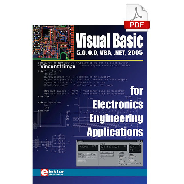
The PC has long-time outgrown its function as a pure computer and has become an all-purpose machine. This book is targeted towards those people that want to control existing or self-built hardware from their computer.
Using Visual Basic as Rapid Application Development tool we will take you on a journey to unlock the world beyond the connectors of the PC.
After familiarising yourself with Visual Basic, its development environment and the toolset it offers, items such as serial communications, printer ports, bit-banging, protocol emulation, ISA, USB and Ethernet interfacing and the remote control of test-equipment over the GPIB bus, are covered in extent. Each topic is accompanied by clear, ready to run code, and where necessary, schematics are provided that will get your projects up to speed in no time.
This book will show you advanced things like: using tools like Debug to find hardware addresses, setting up remote communication using TCP/IP and UDP sockets and even writing your own internet servers. Or how about connecting your own block of hardware over USB or Ethernet and controlling it from Visual Basic. Other things like internet-program communication, DDE and the new graphics interface of Windows XP are covered as well.
All examples are ready to compile using Visual Basic 5.0, 6.0, NET or 2005. Extensive coverage is given on the differences between what could be called Visual Basic Classic and Visual basic .NET / 2005.
Get Cracking with the Arduino Nano V3, Nano Every, and Nano 33 IoT
The seven chapters in this book serve as the first step for novices and microcontroller enthusiasts wishing to make a head start in Arduino programming. The first chapter introduces the Arduino platform, ecosystem, and existing varieties of Arduino Nano boards. It also teaches how to install various tools needed to get started with Arduino Programming. The second chapter kicks off with electronic circuit building and programming around your Arduino. The third chapter explores various buses and analog inputs. In the fourth chapter, you get acquainted with the concept of pulse width modulation (PWM) and working with unipolar stepper motors.
In the fifth chapter, you are sure to learn about creating beautiful graphics and basic but useful animation with the aid of an external display. The sixth chapter introduces the readers to the concept of I/O devices such as sensors and the piezo buzzer, exploring their methods of interfacing and programming with the Arduino Nano. The last chapter explores another member of Arduino Nano family, Arduino Nano 33 IoT with its highly interesting capabilities. This chapter employs and deepens many concepts learned from previous chapters to create interesting applications for the vast world of the Internet of Things.
The entire book follows a step-by-step approach to explain concepts and the operation of things. Each concept is invariably followed by a to-the-point circuit diagram and code examples. Next come detailed explanations of the syntax and the logic used. By closely following the concepts, you will become comfortable with circuit building, Arduino programming, the workings of the code examples, and the circuit diagrams presented. The book also has plenty of references to external resources wherever needed.
An archive file (.zip) comprising the software examples and Fritzing-style circuit diagrams discussed in the book may be downloaded free of charge below.
It is becoming important for microcontroller users to quickly learn and adapt to new technologies and architecture used in high performance 32-bit microcontrollers. Many manufacturers now offer 32-bit microcontrollers as general purpose processors in embedded applications.
ARM provide 32 and 64-bit processors mainly for embedded applications. These days, the majority of mobile devices including mobile phones, tablets, and GPS receivers are based on ARM technology. The low cost, low power consumption, and high performance of ARM processors makes them ideal for use in complex communication and mixed signal applications.
This book makes use of the ARM Cortex-M family of processors in easy-to-follow, practical projects. It gives a detailed introduction to the architecture of the Cortex-M family. Examples of popular hardware and software development kits are described.
The architecture of the highly popular ARM Cortex-M processor STM32F107VCT6 is described at a high level, taking into consideration its clock mechanisms, general input/output ports, interrupt sources, ADC and DAC converters, timer facilities, and more. The information provided here should act as a basis for most readers to start using and programming the STM32F107VCT6 microcontroller together with a development kit.
Furthermore, the use of the mikroC Pro for ARM integrated development environment (IDE) has been described in detail. This IDE includes everything required to create a project; namely an editor, compiler, simulator, debugger, and device programmer.
Although the book is based on the STM32F107VCT6 microcontroller, readers should not find it difficult to follow the projects using other ARM processor family members.