De OWON SDS1102 is een betaalbare benchtop digitale oscilloscoop die solide prestaties combineert met essentiële meetfuncties. Deze 2-kanaals oscilloscoop biedt een bandbreedte van 100 MHz, een sample rate van 1 GS/s, een 7-inch LCD-display en een geheugendiepte van 10 kpts. Daarmee is het een praktische keuze voor dagelijkse elektronicatests, foutopsporing en onderwijs.
De SDS1102 beschikt over een vereenvoudigd triggersysteem met niveau- en flanktriggering, waardoor gangbare signalen eenvoudig kunnen worden vastgelegd en geanalyseerd. Het apparaat is ontworpen voor toepassingen waarvoor geen grote geheugendiepte of geavanceerde triggerfuncties nodig zijn, en biedt een eenvoudige en kostenefficiënte oplossing voor basis-signaalanalyse.
Kenmerken
Bandbreedte: 100 MHz
2 kanalen
Bemonsteringssnelheid: 1 GS/s
Ultradunne behuizing
7-inch lcd met hoge resolutie
Ondersteuning voor SCPI en LabVIEW
Specificaties
Bandbreedte
100 MHz
Horizontale schaal (s/div)
5 ns/div - 1000 s/div
Kanalen
2
Verticale gevoeligheid
5 mV/div - 5 V/div (bij ingang)
DC Gain nauwkeurigheid
3%
Verticale resolutie (A/D)
8 bits (2 kanalen tegelijk)
Ingang
Ingangsimpedantie
1 MΩ, 10 pF
Ingangskoppeling
AC, DC, GND
Max ingangsspanning
± 400 V, CATI, CATII
Passieve probes
x1; 10
Probe verzwakkingsfactor
x1; x10; x100; x1000
Triggersysteem
Trigger mode
Auto, Normal, Single
Trigger type
Flank, Video
Flank triggerbron
CH1, CH2
Video trigger
Sampletype
Real-time
Samplefrequentie
1 GS/s
Equivalente samplesnelheid
No
Golflengte
10K pts
Interpolatie
sin(x)/x
Meet- en rekenkundig bewerkingssysteem
Automatische meting
Vpp, Vavg, RMS, Frequency, Period, Vmax, Vmin, Vtop, Vbase, Width, Overshoot, Pre-shoot Rise time, Fall time, +Width, -Width, +Duty, -Duty, Delay A->B, Delay A->B, area, cycle area
Rekenkundige functies
Addition, Subtraction, Multiplication, Division, FFT
Algemene kenmerken
Display maat
7" color LCD
Display resolutie
800 x 480
Voeding
100-240 V, 45-440 Hz, <15 W
Afmetingen
301 x 70 x 152 mm
Gewicht
1,1 kg
Inbegrepen
1x OWON SDS1102 Oscilloscoop
2x Oscilloscoopsonde
1x Sonde aanpassen
1x Netsnoer
1x USB-kabel
1x CD-Rom
1x Snelstartgids
Downloads
Quick Guide
Manual
PC Software
SCPI Commands
Programmierung in Assembler und C am Beispiel der ATtiny-Familie
Dieses Buch bietet einen eingehenden Blick auf die 8-Bit-AVR-Architektur in ATtiny- und ATmega-Mikrocontrollern, hauptsächlich aus der Sicht der Software und der Programmierung. Erforschen Sie die AVR-Architektur unter Verwendung von C und Assembler in Microchip Studio (früher Atmel Studio) mit ATtiny-Mikrocontrollern.
Lernen Sie die Details der internen Funktionsweise von AVR-Mikrocontrollern kennen, einschließlich der internen Register und des Speicherplans von ATtiny-Bausteinen.
Programmieren Sie ATtiny-Mikrocontroller mit einem Atmel-ICE-Programmiergerät/Debugger oder verwenden Sie ein preiswertes Hobby-Programmiergerät oder sogar einen Arduino Uno als Programmiergerät.
Die meisten Code-Beispiele können mit dem Microchip Studio AVR-Simulator ausgeführt werden.
Lernen Sie, Programme für ATtiny-Mikrocontroller in Assembler zu schreiben.
Erfahren Sie, wie Assemblersprache in Maschinencodebefehle umgewandelt wird.
Finden Sie heraus, wie Programme, die in der Programmiersprache C geschrieben wurden, in Assemblersprache und schließlich in Maschinencode umgewandelt werden.
Verwenden Sie den Microchip Studio Debugger in Kombination mit einem Hardware-USB-Programmierer/Debugger, um Assembler- und C-Programme zu testen oder verwenden Sie den Microchip Studio AVR-Simulator.
ATtiny-Mikrocontroller im DIP-Gehäuse werden verwendet, um eine einfache Nutzung auf Breadboards zu ermöglichen.
Erfahren Sie mehr über Timing und Taktimpuls in AVR-Mikrocontrollern mit ATtiny-Bausteinen.
Werden Sie zu einem AVR-Experten mit fortgeschrittenen Debugging- und Programmierfähigkeiten.
Vanaf nu kunt u uw Arduino boards aansluiten met de officiële Arduino USB kabel. Met deze data USB kabel kan uw Arduino board eenvoudig worden verbonden met een door u gekozen apparaat, via een USB-C naar een USB-C met een USB-A adapter. De Arduino USB kabel heeft een nylon gevlochten mantel in de typische Arduino kleuren wit en groenblauw. De connectoren hebben een aluminium omhulsel dat uw kabel beschermt tegen schade en er meteen ook cool uitziet. Lengte: 100 cm Aluminium omhulsel met logo Nylon gevlochten mantel in wit en groenblauw
Entièrement mise à jour pour le Raspberry Pi 5
Raspberry Pi 5 est un petit ordinateur intelligent, de construction britannique qui regorge de potentiel. Fabriqué à l'aide d'un processeur économe en énergie, le Raspberry Pi est conçu pour vous aider à apprendre le codage, découvrir comment fonctionne un ordinateur et construire vos propres projets uniques et incroyables. Ce guide est conçu pour vous montrer à quel point il est facile de démarrer.
Apprendre à :
Configurez votre Raspberry Pi, installez son système d'exploitation, et commencez à utiliser cet ordinateur entièrement fonctionnel.
Commencez à coder des projets, avec des guides étape par étape utilisant les langages de programmation Scratch 3, Python et MicroPython.
Expérimentez en connectant des composants électroniques, et amusez-vous à créer des projets incroyables.
Nouveauté de la 5ème édition :
Mise à jour pour les derniers ordinateurs Raspberry Pi : Raspberry Pi 5 et Raspberry Pi Zèro 2 W.
Couvre le dernier système d'exploitation Raspberry Pi.
Comprend un nouveau chapitre sur le Raspberry Pi Pico !
Téléchargements
GitHub
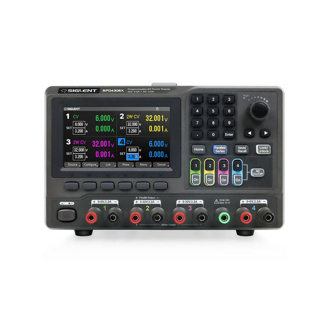
The Siglent SPD4306X is a 4-channel DC Linear Programmable Power Supply equipped with a 4.3-inch TFT-LCD display, friendly human-machine interface, and excellent performance indicators. Real-time waveform display provides engineers with an informative user interface.
SPD4306X offers a total output power of 400 W with a resolution of 1 mV/1 mA. The maximum voltage and current for each channel are as follows:
CH1: 15 V/1.5 A
CH2: 30 V/6 A
CH3: 30 V/6 A
CH4: 15 V/1 A
Kenmerken
Rated output power: 400 W
Rated voltage: 32 V, 12 V, 30 V
Up to four high-precision power supplies with independent controllable outputs, supporting CH2 and CH3 series and parallel connections
Clear graphical interface with waveform and timer display modes
5-digit voltage and current display with minimum resolution of 1 mV, 1 mA
Fast output response time: <50us
The high current channel support remote voltage compensation sense function. The maximum compensation voltage is 0.6 V
Overvoltage protection and overcurrent protection or safe and accurate operation
Equipped with a 4.3-inch TFT-LCD display (480 x 272 resolution)
USB and LAN standard communication
USB-GPIB module is optional
Excellent channel density with up to 4 channels in a 3U half rack package
Internal data storage for setups and parameters
Embedded Web Server with instrument communication that doesn’t require software installation
Fully SCPI programming command set support as well as a LabView driver for remote control and system automation
Specificaties
SPD4323X
SPD4121X
SPD4306X
Channel Output
CH1: Voltage 0 to 6 V Current 0 to 3.2 ACH2: Voltage 0 to 32 V Current 0 to 3.2 ACH3: Voltage 0 to 32 V Current 0 to 3.2 ACH4: Voltage 0 to 6 V Current 0 to 3.2 A
CH1: Voltage 0 to 15 V Current 0 to 1.5 ACH2: Voltage 0 to 12 V Current 0 to 10 ACH3: Voltage 0 to 12 V Current 0 to 10 ACH4: Voltage 0 to 15 V Current 0 to 1.5 A
CH1: Voltage 0 to 15 V Current 0 to 1.5 ACH2: Voltage 0 to 30 V Current 0 to 6 ACH3: Voltage 0 to 30 V Current 0 to 6 ACH4: Voltage 0 to 15 V Current 0 to 1 A
Resolution
1 mV, 1 mA
1 mV, 1 mA
1 mV, 1 mA
Setting Accuracy
Voltage: ±(0.03% of reading+10) mV, Current: ±(0.3% of reading+10) mA
Voltage: ±(0.03% of reading+10) mV, Current: ±(0.3% of reading+10) mA
Voltage: ±(0.03% of reading+10) mV, Current: ±(0.3% of reading+10) mA
Readback Accuracy
Voltage: ±(0.03% of reading+10) mV, Current: ±(0.3% of reading+10) mA
Voltage: ±(0.03% of reading+10) mV, Current: ±(0.3% of reading+10) mA
Voltage: ±(0.03% of reading+10) mV, Current: ±(0.3% of reading+10) mA
Display
4.3" TFT-LCD 5-digit voltage and current display
4.3" TFT-LCD 5-digit voltage and current display
4.3" TFT-LCD 5-digit voltage and current display
Output power
240 W
285 W
400 W
Inbegrepen
1x Siglent SPD4306X Power Supply
1x Power cord (EU)
1x Output test cord (3 A)
1x USB cable
1x Quick start guide
Downloads
Datasheet
Manual
Quick start
Mikrocontroller haben sich in den letzten Jahren in praktisch allen Bereichen der modernen Technik etabliert. In zunehmendem Maße dringen sie auch in die Gebiete der Künstlichen Intelligenz und der Robotertechnik vor. Das vorliegende Buch gibt eine umfassende Einführung in die Welt der Controller-Technik mit all ihren Facetten, von der einfachen Steuerung über die Sensor-Technik bis hin zur Datenübertragung in das Internet.
Als Basis dafür dient das von Elektor entwickelte AVR-Playground-Board. Das Board kann mit Controllern der ATmega-Familie bestückt werden und ist mit dem bekannten Arduino-System kompatibel, so dass auch die verschiedenen Arduino-Hardware-Erweiterungen verwendet werden können.
Für die Programmierung kommt die Sprache „C“ zum Einsatz. Auch hier wird im Buch auf das Arduino-System zurückgegriffen. Die frei verfügbare Arduino-Entwicklungsumgebung erlaubt den leichten Einstieg, ohne dass später Einschränkungen in Kauf genommen werden müssen. Die Hardware-nahe Programmierung steht dabei besonders im Fokus. Nach der Erläuterung von grundlegenden Anwendungen wird auf die anspruchsvolleren Themen wie Interrupts, Timer und Counter, Pulsweitenmodulation und Analog-Digital-Wandlung eingegangen.
Praktische Anwendungen können sowohl mit einem Arduino als auch mit dem AVR-Playground-Board durchgeführt werden. Da das AVR-Playground-Board bereits über eine Vielzahl von Peripherie-Einheiten verfügt, sind nur noch wenige externe Bauteile erforderlich. Das Board kann im Elektor-Shop hier bezogen werden.
It is becoming important for microcontroller users to quickly learn and adapt to new technologies and architecture used in high performance 32-bit microcontrollers. Many manufacturers now offer 32-bit microcontrollers as general purpose processors in embedded applications.
ARM provide 32 and 64-bit processors mainly for embedded applications. These days, the majority of mobile devices including mobile phones, tablets, and GPS receivers are based on ARM technology. The low cost, low power consumption, and high performance of ARM processors makes them ideal for use in complex communication and mixed signal applications.
This book makes use of the ARM Cortex-M family of processors in easy-to-follow, practical projects. It gives a detailed introduction to the architecture of the Cortex-M family. Examples of popular hardware and software development kits are described.
The architecture of the highly popular ARM Cortex-M processor STM32F107VCT6 is described at a high level, taking into consideration its clock mechanisms, general input/output ports, interrupt sources, ADC and DAC converters, timer facilities, and more. The information provided here should act as a basis for most readers to start using and programming the STM32F107VCT6 microcontroller together with a development kit.
Furthermore, the use of the mikroC Pro for ARM integrated development environment (IDE) has been described in detail. This IDE includes everything required to create a project; namely an editor, compiler, simulator, debugger, and device programmer.
Although the book is based on the STM32F107VCT6 microcontroller, readers should not find it difficult to follow the projects using other ARM processor family members.
The 8x10" iFixit Magnetic Project Mat catches and securely holds screws as you pull them out of a device. Now you can stop worrying about keeping track of all the loose screws and focus on your repair. Screws and small parts will remain right where you left them. For laptops with hundreds of screws, use the whole mat as a screw guide and keep careful location notes.
Included is a pen — made by Staedtler, producer of top-of-the-line pens and pencils for artists and architects — that was specially designed for the Project Mat. The Lumocolor Correctable pen resists smears and won't wipe away with a casual brush of your hand. When your repair is complete, use the eraser tip or a dry cloth to wipe the ink away clean.
Kenmerken
Organize all your small parts while you work on a device.
The dry-erase surface lets you keep notes and location sketches.
Reduces reassembly time by up to 40% while preventing errors.
Raspberry Pi 5 provides two four-lane MIPI connectors, each of which can support either a camera or a display. These connectors use the same 22-way, 0.5 mm-pitch “mini” FPC format as the Compute Module Development Kit, and require adapter cables to connect to the 15-way, 1 mm-pitch “standard” format connectors on current Raspbery Pi camera and display products.These mini-to-standard adapter cables for cameras and displays (note that a camera cable should not be used with a display, and vice versa) are available in 200 mm, 300 mm and 500 mm lengths.
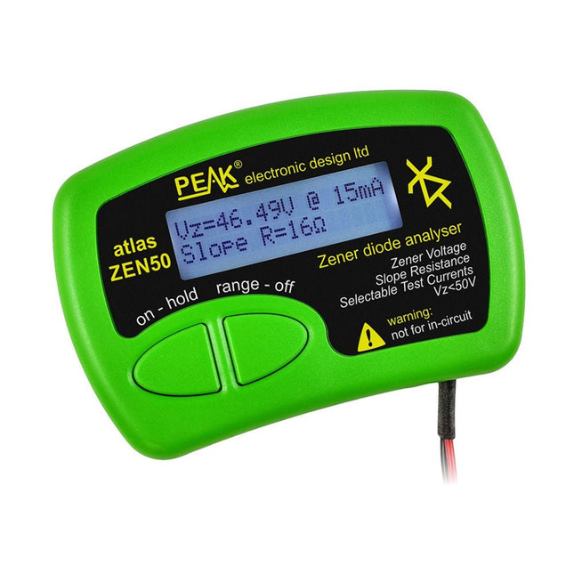
The Peak Atlas ZEN50 is ideal for testing Zener diodes (including avalanche diodes), transient suppressors, LEDs and LED strings. It generates constant current pulses (selectable from 2 mA, 5 mA, 10 mA and 15 mA) at voltages from 0V to 50V. So even high voltage Zeners or high voltage LED strings can be tested.
Test currents are supplied in narrow pulses to ensure that the component under test remains at a constant temperature.
The voltage of the part is displayed on the screen together with the test current and also a measure of the component's slope resistance (also known as dynamic impedance).
Specificaties
Analyzer type
Zeners, LEDs, TVS etc
Test currents
2 mA, 5 mA, 10 mA, 15 mA
Voltage range
0.00 to 50.00 V
Slope resistance range
0 to 8000 Ohms
Battery type
Single AAA (supplied). Life typically 1400 ops
Test method
Triple pulse burst @ 10pps (typ)
Test current duty cycle
3%
Display type
Alphanumeric LCD (with backlight)
Inbegrepen
Peak Atlas ZEN50 Zener Diode Analyzer
Fitted flexible test leads with gold plated crocs
Comprehensive illustrated user guide
AAA Alkaline battery
Downloads
Datasheet (EN)
User Guide (EN)
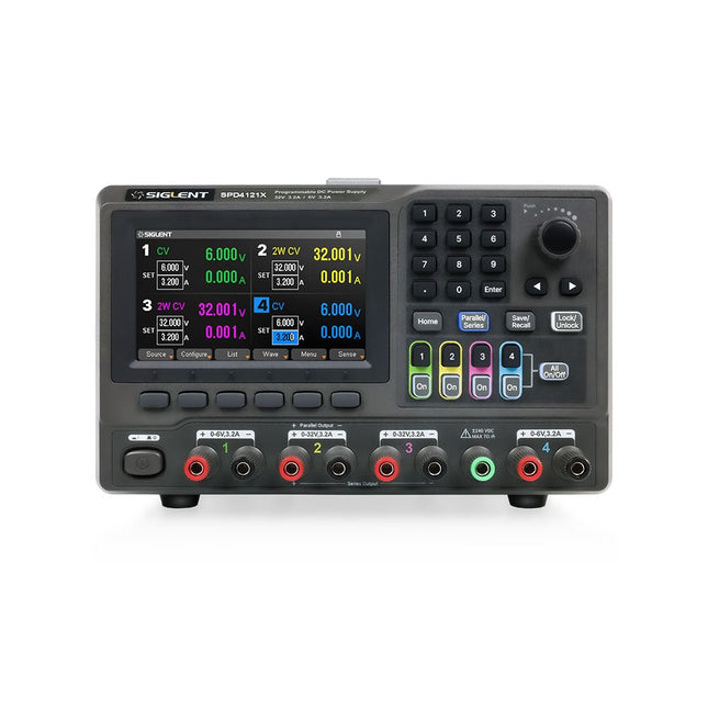
The Siglent SPD4121X is a 4-channel DC Linear Programmable Power Supply equipped with a 4.3-inch TFT-LCD display, friendly human-machine interface, and excellent performance indicators. Real-time waveform display provides engineers with an informative user interface.
SPD4121X offers a total output power of 285 W with a resolution of 1 mV/1 mA. The maximum voltage and current for each channel are as follows:
CH1: 15 V/1.5 A
CH2: 12 V/10 A
CH3: 12 V/10 A
CH4: 15 V/1.5 A
Kenmerken
Rated output power: 285 W
Rated voltage: 32 V, 12 V, 30 V
Up to four high-precision power supplies with independent controllable outputs, supporting CH2 and CH3 series and parallel connections
Clear graphical interface with waveform and timer display modes
5-digit voltage and current display with minimum resolution of 1 mV, 1 mA
Fast output response time: <50us
The high current channel support remote voltage compensation sense function. The maximum compensation voltage is 0.6 V
Overvoltage protection and overcurrent protection or safe and accurate operation
Equipped with a 4.3-inch TFT-LCD display (480 x 272 resolution)
USB and LAN standard communication
USB-GPIB module is optional
Excellent channel density with up to 4 channels in a 3U half rack package
Internal data storage for setups and parameters
Embedded Web Server with instrument communication that doesn’t require software installation
Fully SCPI programming command set support as well as a LabView driver for remote control and system automation
Specificaties
SPD4323X
SPD4121X
SPD4306X
Channel Output
CH1: Voltage 0 to 6 V Current 0 to 3.2 ACH2: Voltage 0 to 32 V Current 0 to 3.2 ACH3: Voltage 0 to 32 V Current 0 to 3.2 ACH4: Voltage 0 to 6 V Current 0 to 3.2 A
CH1: Voltage 0 to 15 V Current 0 to 1.5 ACH2: Voltage 0 to 12 V Current 0 to 10 ACH3: Voltage 0 to 12 V Current 0 to 10 ACH4: Voltage 0 to 15 V Current 0 to 1.5 A
CH1: Voltage 0 to 15 V Current 0 to 1.5 ACH2: Voltage 0 to 30 V Current 0 to 6 ACH3: Voltage 0 to 30 V Current 0 to 6 ACH4: Voltage 0 to 15 V Current 0 to 1 A
Resolution
1 mV, 1 mA
1 mV, 1 mA
1 mV, 1 mA
Setting Accuracy
Voltage: ±(0.03% of reading+10) mV, Current: ±(0.3% of reading+10) mA
Voltage: ±(0.03% of reading+10) mV, Current: ±(0.3% of reading+10) mA
Voltage: ±(0.03% of reading+10) mV, Current: ±(0.3% of reading+10) mA
Readback Accuracy
Voltage: ±(0.03% of reading+10) mV, Current: ±(0.3% of reading+10) mA
Voltage: ±(0.03% of reading+10) mV, Current: ±(0.3% of reading+10) mA
Voltage: ±(0.03% of reading+10) mV, Current: ±(0.3% of reading+10) mA
Display
4.3" TFT-LCD 5-digit voltage and current display
4.3" TFT-LCD 5-digit voltage and current display
4.3" TFT-LCD 5-digit voltage and current display
Output power
240 W
285 W
400 W
Inbegrepen
1x Siglent SPD4121X Power Supply
1x Power cord (EU)
1x Output test cord (3 A)
1x USB cable
1x Quick start guide
Downloads
Datasheet
Manual
Quick start