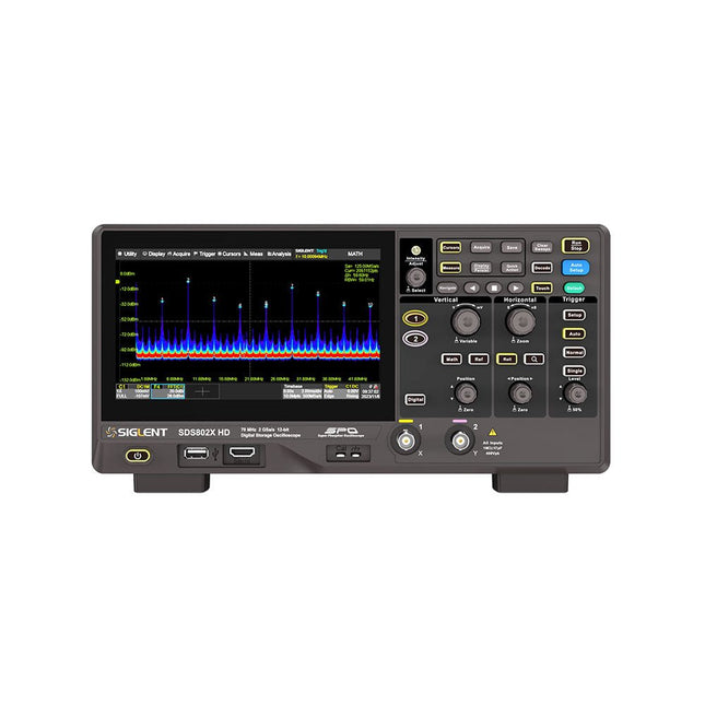
De OWON SDS1102 is een betaalbare benchtop digitale oscilloscoop die solide prestaties combineert met essentiële meetfuncties. Deze 2-kanaals oscilloscoop biedt een bandbreedte van 100 MHz, een sample rate van 1 GS/s, een 7-inch LCD-display en een geheugendiepte van 10 kpts. Daarmee is het een praktische keuze voor dagelijkse elektronicatests, foutopsporing en onderwijs.
De SDS1102 beschikt over een vereenvoudigd triggersysteem met niveau- en flanktriggering, waardoor gangbare signalen eenvoudig kunnen worden vastgelegd en geanalyseerd. Het apparaat is ontworpen voor toepassingen waarvoor geen grote geheugendiepte of geavanceerde triggerfuncties nodig zijn, en biedt een eenvoudige en kostenefficiënte oplossing voor basis-signaalanalyse.
Kenmerken
Bandbreedte: 100 MHz
2 kanalen
Bemonsteringssnelheid: 1 GS/s
Ultradunne behuizing
7-inch lcd met hoge resolutie
Ondersteuning voor SCPI en LabVIEW
Specificaties
Bandbreedte
100 MHz
Horizontale schaal (s/div)
5 ns/div - 1000 s/div
Kanalen
2
Verticale gevoeligheid
5 mV/div - 5 V/div (bij ingang)
DC Gain nauwkeurigheid
3%
Verticale resolutie (A/D)
8 bits (2 kanalen tegelijk)
Ingang
Ingangsimpedantie
1 MΩ, 10 pF
Ingangskoppeling
AC, DC, GND
Max ingangsspanning
± 400 V, CATI, CATII
Passieve probes
x1; 10
Probe verzwakkingsfactor
x1; x10; x100; x1000
Triggersysteem
Trigger mode
Auto, Normal, Single
Trigger type
Flank, Video
Flank triggerbron
CH1, CH2
Video trigger
Sampletype
Real-time
Samplefrequentie
1 GS/s
Equivalente samplesnelheid
No
Golflengte
10K pts
Interpolatie
sin(x)/x
Meet- en rekenkundig bewerkingssysteem
Automatische meting
Vpp, Vavg, RMS, Frequency, Period, Vmax, Vmin, Vtop, Vbase, Width, Overshoot, Pre-shoot Rise time, Fall time, +Width, -Width, +Duty, -Duty, Delay A->B, Delay A->B, area, cycle area
Rekenkundige functies
Addition, Subtraction, Multiplication, Division, FFT
Algemene kenmerken
Display maat
7" color LCD
Display resolutie
800 x 480
Voeding
100-240 V, 45-440 Hz, <15 W
Afmetingen
301 x 70 x 152 mm
Gewicht
1,1 kg
Inbegrepen
1x OWON SDS1102 Oscilloscoop
2x Oscilloscoopsonde
1x Sonde aanpassen
1x Netsnoer
1x USB-kabel
1x CD-Rom
1x Snelstartgids
Downloads
Quick Guide
Manual
PC Software
SCPI Commands
The Siglent SDS814X HD digital storage oscilloscope is based on 2 GSa/s, 12-bit Analog-Digital Converters and front ends with excellent noise floor performance. With a 100 MHz bandwidth, and a maximum record length of 50 Mpts, and the capability to analyze 4 analog channels alongside 16 digital channels, the SDS814X HD is perfectly suited for mixed signal analysis.
Kenmerken
12-bit High Resolution
12-bit Analog-Digital Convertors with sample rate up to 2 GSa/s
Front ends with 70 μVrms noise floor @ 100 MHz bandwidth
2/4 analog channels, up to 700 MHz bandwidth
SPO technology
Waveform capture rate up to 80,000 wfm/s (normal mode), and 500,000 wfm/s (sequence mode)
Supports 256-level intensity grading and color temperature display modes.
Up to 50 Mpts record length
Digital trigger system
Intelligent trigger: Edge, Slope, Pulse width, Window, Runt, Interval, Dropout, Pattern, Video (HDTV supported), Qualified, Nth edge, Delay, Setup/Hold time.
Serial bus triggering and decoder, supports protocols I²C, SPI, UART, CAN, LIN.
Segmented acquisition (Sequence) mode, dividing the maximum record length into multiple segments (up to 80,000), according to trigger conditions set by the user, with a very small dead time between segments to capture the qualifying event.
History waveform record (History) function, the maximum recorded waveform length is 80,000 frames.
Automatic measurements on 50+ parameters, supports statistics with histogram, track, trend, Gating measurement, and measurements on Math, History and Ref.
4 Math traces (2 Mpts FFT, addition, subtraction, multiplication, division, integration, differential, square root, etc.), supports formula editor.
Abundant data analysis functions such as Search, Navigate, Counter, Bode plot and Power Analysis
High Speed hardware-based Mask Test function, with Mask Editor tool for creating user-defined masks
16 digital channels (optional)
25 MHz waveform generator (optional)
7" TFT-LCD display with 1024 x 600 resolution; Capacitive touch screen supports multi-touch gestures.
Interfaces include: USB Hosts, USB Device (USBTMC), LAN (VXI-11/Telnet/Socket), Pass/Fail, Trigger Out
Built-in web server supports remote control over the LAN port using a web browser. Supports SCPI remote control commands. Supports external mouse and keyboard. Supports NTP.
Specificaties
Analog Channels
4
Bandwidth
100 MHz
Vertical resolution
12-bit
Sample rate (Max.)
One channel mode: 2 GSa/sTwo channel mode: 1 GSa/sFour channel mode: 500 MSa/s
Memory depth (Max.)
One channel mode: 50 Mpts/chTwo channel mode: 25 Mpts/chFour channel mode: 10Mpts/ch
Waveform capture rate (Max.)
Normal mode: 80,000 wfm/sSequence mode: 500,000 wfm/s
Trigger type
Edge, Slope, Pulse width, Window, Runt, Interval, Dropout, Pattern, Video, Qualified, Nth edge, Delay, Setup/Hold time, Serial
Serial trigger and decode (Standard)
I²C, SPI, UART, CAN, LIN
Measurement
50+ parameters, statistics, histogram, trend, and track supported
Math
4 traces 2 Mpts FFT, Filter, +, -, x, ÷, ∫dt, d/dt, √, Identity, Negation, Absolute, Sign, ex, 10x, ln, lg, Interpolation, MaxHold, MinHold, ERES, Average. Supports formula editor
Data analysis
Search, Navigate, History, Mask Test, Counter, Bode plot, and Power Analysis
Digital channel (optional)
16-channel; maximum sample rate up to 1 GSa/s; record length up to 10 Mpts
USB AWG module (option)
One channel, 25 MHz, sample rate of 125 MHz, wave length of 16 kpts, isolated output
I/O
2x USB 2.0 Host, USB 2.0 Device, 10/100 M LAN, Auxiliary output (TRIG OUT, PASS/FAIL), SBUS (Siglent MSO)
Probe (Standard)
Passive probe PB470 for each channel
Display
7 TFT-LCD with capacitive touch screen (1024x600)
Inbegrepen
1x Siglent SDS814X Oscilloscope
4x Passive probe (100 MHz) PP510
1x Power cord (EU)
1x USB cable
1x Certificate of calibration
1x Quick start
Downloads
Datasheet
Manual
Programming guide
Mit dem Elektor Arduino Nano Trainingsboard (MCCAB) eigene Projekte realisieren
Der Mikrocontroller ist das wohl faszinierendste Teilgebiet der Elektronik, denn aufgrund der Vielzahl von Funktionen, die er auf seinem Chip vereinigt, ist er für den Entwickler ein universelles Multi-Tool zur Realisierung seiner Projekte. Praktisch jedes Gerät des täglichen Gebrauchs wird heute von einem Mikrocontroller gesteuert. Für einen elektronischen Laien blieb es aufgrund der Komplexität bisher allerdings ein Wunschtraum, eigene Ideen mit einem Mikrocontroller zu realisieren. Das Arduino-Konzept hat den Einsatz von Mikrocontrollern weitgehend vereinfacht, sodass jetzt auch Laien eigene Elektronik-Ideen mit einem Mikrocontroller verwirklichen können.
Buch & Hardware im Bundle: 'Learning by Doing'
Dieses im Bundle mitgelieferte Buch (im großen A4-Format) zeigt, wie man auch ohne große Erfahrung in Elektronik und Programmiersprachen eigene Projekte mit einem Mikrocontroller realisieren kann. Es ist ein Mikrocontroller-Praxiskurs für Einsteiger, denn nach einem Überblick über die Interna des Mikrocontrollers und einer Einführung in die Programmiersprache C liegt der Schwerpunkt des Kurses auf den praktischen Übungen. Der Leser eignet sich die erforderlichen Kenntnisse durch 'Learning by Doing' an: in dem umfangreichen Praxisteil mit 12 Projekten und 46 Übungen wird das im vorderen Teil des Buches Gelernte mit vielen Beispielen unterlegt. Die Übungen sind dabei so aufgebaut, dass der Bearbeiter eine Aufgabenstellung erhält, die er mit seinem im Theorieteil des Buches aufgebauten Wissen löst. Für jede Übung gibt es anschließend eine ausführlich erklärte und kommentierte Musterlösung, die dem Bearbeiter bei Problemen weiterhilft und die er mit seiner eigenen Lösung vergleichen kann.
Arduino IDE
In der Arduino IDE, einer Software-Entwicklungsumgebung, die kostenlos auf den eigenen PC heruntergeladen werden kann und die das gesamte Softwarepaket enthält, das für ein eigenes Mikrocontroller-Projekt benötigt wird, schreibt der Bearbeiter mit dem Editor der IDE seine Programme („Apps“) in der Programmiersprache C. Der in die Arduino IDE integrierte Compiler übersetzt sie in die Bits und Bytes, die der Mikrocontroller versteht und die dann über ein USB-Kabel in den Speicher des Mikrocontrollers auf dem Elektor Arduino Nano Trainingsboard (MCCAB) geladen werden.
Externe Sensoren, Motoren oder Baugruppen abfragen oder steuern
Das Elektor Arduino Nano Trainingsboard (MCCAB) enthält neben einem Mikrocontrollermodul Arduino Nano alle für die Übungen benötigten Bauteile wie Leuchtdioden, Schalter, Taster, akustische Signalgeber usw. Auch externe Sensoren, Motoren oder Baugruppen können mit diesem Mikrocontroller-Übungssystem abgefragt oder gesteuert werden.
Technische Daten (Arduino Nano Trainingsboard MCCAB)
Stromversorgung
Über die USB-Verbindung des zur Erstellung der Programme sowieso angeschlossenen PCs oder ein externes Netzteil (nicht im Lieferumfang enthalten)
Betriebsspannung
+5 Vcc
Eingangsspannung
Alle Eingänge
0 V bis +5 V
VX1 und VX2
+8 V bis +12 V (nur bei Verwendung eines externen Netzteils)
Mikrocontrollermodul
Arduino Nano
Hardwareperipherie
LCD
2x16 Zeichen
Potenziometer P1 & P2
JP3: Auswahl der Betriebsspannung von P1 & P2
Verteiler
SV4: Verteiler für die BetriebsspannungenSV5, SV6: Verteiler für die Ein-/Ausgänge des Mikrocontrollers
Schalter und Taster
RESET-Taster auf dem Arduino Nano-Modul6x Tastschalter K1 … K66x Schiebeschalter S1 … S6JP2: Verbindung der Schalter mit den Eingängen des Mikrocontrollers
Summer
Piezo-Summer Buzzer1 mit Steckbrücke auf JP6
Leuchtanzeigen
LED L auf dem Arduino Nano-Modul, verbunden mit GPIO D1311x LED: Zustandsanzeige für die Ein-/AusgängeJP6: Verbindung der LEDs LD10 … LD20 mit den GPIOs D2 … D12
Serielle SchnittstellenSPI & I²C
JP4: Auswahl des Signals an Pin X der SPI-Steckerleiste SV12SV9 bis SV12: SPI-Interface (3,3 V/5 V) bzw. I²C-Interface
Schaltausgang für externe Geräte
SV1, SV7: Schaltausgang (maximal +24 V/160 mA, extern zugeführt)SV2: 2x13 Pins zum Anschluss externer Module
3x3 LED-Matrix (9 rote LEDs)
SV3: Spalten der 3x3 LED-Matrix (Ausgänge D6 … D8)JP1: Verbindung der Reihen mit den GPIOs D3 … D5
Software
Library MCCABLib
Steuerung der Hardware-Komponenten (Schalter, Taster, Leuchtdioden, 3x3 LED-Matrix, Summer) auf dem MCCAB Trainingsboard
Betriebstemperatur
bis +40 °C
Abmessungen
100 x 100 x 20 mm
Technische Daten (Arduino Nano)
Mikrocontroller
ATmega328P
Architektur
AVR
Betriebsspannung
5 V
Flashspeicher
32 KB, davon 2 KB vom Bootloader belegt
SRAM
2 KB
Taktfrequenz
16 MHz
Analoge IN-Pins
8
EEPROM
1 KB
DC-Strom pro I/O-Pin
40 mA an einem I/O-Pin, insgesamt maximal 200 mA an allen Pins gemeinsam
Eingangsspannung
7-12 V
Digitale I/O-Pins
22 (6 davon sind PWM-fähig)
PWM-Ausgänge
6
Stromverbrauch
19 mA
Abmessungen
18 x 45 mm
Gewicht
7 g
Lieferumfang
Elektor Arduino Nano MCCAB Trainingsboard
Arduino Nano
Buch: Mikrocontroller-Praxiskurs für Arduino-Einsteiger
Siglent's SDS2000X Plus series Digital Storage Oscilloscopes are available in bandwidths of 100 MHz, 200 MHz, and 350 MHz, have a maximum sample rate of 2 GSa/s, a maximum record length of 200 Mpts/ch, and up to 4 analog channels + 16 digital channels mixed-signal analysis ability.
The SDS2000X Plus series employs Siglent’s SPO technology with a maximum waveform capture rate of up to 120,000 wfm/s (normal mode, up to 500,000 wfm/s in Sequence mode), 256-level intensity grading display function plus a color temperature display mode. It also employs an innovative digital trigger system with high sensitivity and low jitter. The trigger system supports multiple powerful triggering modes including serial bus triggering. History waveform recording, Sequence acquisition, Search and Navigate functions allow for extended waveform records to be captured, stored, and analyzed. An impressive array of measurement and math capabilities, options for a 50 MHz waveform generator, as well as serial decoding, mask test, bode plot, and power analysis are also features of the SDS2000X Plus. A 10-bit acquisition mode helps to satisfy applications that require more than 8-bit resolution.
The large 10.1’’ capacitive touch screen supports multi-touch gestures, while the remote web control, mouse and external keyboard support greatly improve the operating efficiency of the SDS2000X Plus.
Features
100 MHz, 200 MHz, 350 MHz (upgradable to 500 MHz) models
Real-time sampling rate up to 2 GSa/s
Record length up to 200 Mpts
Serial bus triggering and decoder, supports I²C, SPI, UART, CAN, LIN, CAN FD, FlexRay, I²S and MIL-STD-1553B
Provide 10 bit mode, Vertical and Horizontal Zoom
Capacitive touch screen supports multi-touch gestures
Siglent SDS2000X Plus Oscilloscopes
SDS2102X Plus
SDS2104X Plus
SDS2204X Plus
SDS2354X Plus
Bandwidth
100 MHz
100 MHz
200 MHz
350 MHz
Channels
2
4
4
4
Real-time sampling rate
2 GSa/s
2 GSa/s
2 GSa/s
2 GSa/s
Capture rate
120,000 wfm/s
120,000 wfm/s
120,000 wfm/s
120,000 wfm/s
Memory depth
200 Mpts/ch
200 Mpts/ch
200 Mpts/ch
200 Mpts/ch
Included
Siglent SDS2354X Plus Oscilloscope
Passive probes
Power cord
USB cable
Manual
Downloads
Datasheet
Manual
Quick guide
User manual
Firmware
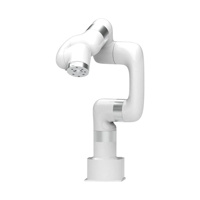
This multi-axis robot perfectly balances power and size.
Features
5 Axis
Payload: 3 kg
Reach: 700 mm
Repeatability: 0.1 mm
Max Speed 1000 mm/s
Applications
Machine Tending
Bin Picking
Mobile platform
Lab Automation
Robotic Research
Durable Collaborative robots for your automation
Industrial-grade harmonic drive and servomotors guarantee 24/7 working without stop.
Crafted from Carbon fiber, 15 kg weight makes it possible for easier deployment.
Flexible deployment with safe feature
Hand teaching, lightweight, space-saving and easy to re-deploy to multiple applications without changing your production layout. Perfectly for recurrent tasks.
Collision detection is available for all of our cobots. Your safety is always the top priority.
Graphical interface for beginner-friendly programming
Compatible with various of operation systems, including macOS and Windows.
Web-based technology compatible with all major browsers.
Drag and drop to create your code in minutes.
Powerful and open source SDK at your fingertips
Fully functional open-source Python/C++ SDK provides more flexible programming.
ROS/ROS2 packages are ready-to-go.
Example codes help you to deploy the robotic arm smoothly.
Specifications
UFactory 850
xArm 5
xArm 6
xArm 7
Payload
5 kg
3 kg
5 kg
3.5 kg
Reach
850 mm
700 mm
700 mm
700 mm
Degrees of freedom
6
5
6
7
Repeatability
±0.02 mm
±0.1 mm
±0.1 mm
±0.1 mm
Maximum Speed
1 m/s
1 m/s
1 m/s
1 m/s
Weight (robot arm only)
20 kg
11.2 kg
12.2 kg
13.7 kg
Maximum Speed
180°/s
180°/s
180°/s
180°/s
Joint 1
±360°
±360°
±360°
±360°
Joint 2
-132°?132°
-118°?120°
-118°?120°
-118°?120°
Joint 3
-242°~3.5°
-225°~11°
-225°~11°
±360°
Joint 4
±360°
-97°~180°
±360°
-11°?225°
Joint 5
-124°~124°
±360°
-97°~180°
±360°
Joint 6
±360°
±360°
-97°~180°
Joint 7
±360°
Hardware
Ambient Temperature Range
0-50°C
Power Consumption
Min 8.4 W, Typical 200 W, max 400 W
Input Power Supply
24 V DC, 16.5 A
Footprint
Ø 126 mm
Materials
Aluminum, Carbon Fiber
Base Connector Type
M5x5
ISO Class Cleanroom
5
Robot Mounting
Any
End Effector Communication Protocol
Modbus RTU(rs485)
End Effector I/O
2x DI/2x DO/2x AI/1x RS485
Communication Mode
Ethernet
Included
1x xArm 5 robotic arm
1x AC control box
1x Robotic arm power cable
1x Robotic arm end effector adapter cable
1x Robotic arm signal cable
1x Control box power cable
1x Network cable
1x Mounting tool
1x Quick start guide
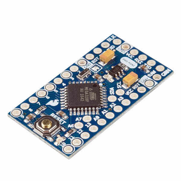
De Arduino Pro Mini is een microcontroller board gebaseerd op de ATmega328P.
Het heeft 14 digitale in-/uitgangspinnen (waarvan er 6 kunnen worden gebruikt als PWM-uitgangen), 6 analoge ingangen, een on-board resonator, een reset-knop, en gaten voor het monteren van pin headers. Een six-pin header kan worden aangesloten op een FTDI-kabel of Sparkfun breakout board om USB-voeding en communicatie te bieden aan de board.
De Arduino Pro Mini is bedoeld voor semi-permanente installatie in voorwerpen of tentoonstellingen. Het board komt zonder pre-gemonteerde headers, waardoor het gebruik van diverse types van schakelaars of het directe solderen van draden is toegestaan. De pin lay-out is compatibel met Arduino Mini.
Specificaties
Microcontroller
ATmega328P
Boord Stroomvoorziening
5-12 V
Circuit Werkspanning
5 V
Digitale I/O Pinnen
14
PWM Pennen
6
UART
1
SPI
1
I²C
1
Analoge ingangspinnen
6
Externe Onderbrekingen
2
DC stroom per I/O Pin
40 mA
Flash Geheugen
32 KB waarvan 2 KB gebruikt door bootloader
SRAM
2 KB
EEPROM
1 KB
Kloksnelheid
16 MHz
Afmetingen
18 x 33,3 mm
Downloads
Eagle files
Schematics
The Siglent SDS1204X-E is a powerful 200 MHz four-channel oscilloscope that is built on the same platform as the very popular SDS1202X-E but with several significant improvements, including two 1 GSa/s ADCs and two 14 Mpt memory modules. Waveform capture rates are up to 100,000 wfms/s in normal mode and 400,000 wfms/s in sequence mode. The SDS1000X-E scopes feature a large 7” 256-level color display with intensity grading and color temperature features.
Specificaties
Bandwidth
200 MHz
Sampling Rate (Max.)
1 GSa/s
Channels
2CH+EXT4CH
Memory Depth (Max.)
7 Mpts/CH (not interleave mode); 14 Mpts/CH (interleave mode)
Waveform Capture Rate (Max.)
100,000 wfms/s (normal mode), 400,000 wfms/s (sequence mode)
Trigger Types
Edge, Slope, Pulse width, Window, Runt, Interval, Dropout, Pattern, Video
Serial Trigger (Standard)
I2C, SPI, UART/RS232, CAN, LIN
Decode Type (Standard)
I2C, SPI, UART/RS232, CAN, LIN
16 Digital Channels (four channel series only, option)
Maximum waveform capture rate up to 1 GSa/s, Record length up to 14 Mpts/CH
USB AWG module (four channel series only, option)
One channel, 25 MHz, sample rate of 125 MHz, wave length of 16 kpts
Bode plot ( four channel series only)
Minimum start frequency of 10 Hz, minimum scan bandwith of 500 Hz, maximum scan bandwidth of 120 MHz (dependent on Oscilloscope and AWG bandwidth), 500 maximum scan frequency points
USB WIFI adapter (four channel series only, option)
802.11b/g/b, WPA-PSK, the adapter must be supplied by Siglent to ensure proper functioning
Downloads
Datasheet
Manual
Programming Guide
The Siglent SDS822X HD digital storage oscilloscope is based on 2 GSa/s, 12-bit Analog-Digital Converters and front ends with excellent noise floor performance. With a 200 MHz bandwidth, and a maximum record length of 100 Mpts, and the capability to analyze 2 analog channels alongside 16 digital channels, the SDS822X HD is perfectly suited for mixed signal analysis.
Kenmerken
12-bit High Resolution
12-bit Analog-Digital Convertors with sample rate up to 2 GSa/s
Front ends with 70 μVrms noise floor @ 200 MHz bandwidth
2/4 analog channels, up to 700 MHz bandwidth
SPO technology
Waveform capture rate up to 120,000 wfm/s (normal mode), and 500,000 wfm/s (sequence mode)
Supports 256-level intensity grading and color temperature display modes.
Up to 50 Mpts record length
Digital trigger system
Intelligent trigger: Edge, Slope, Pulse width, Window, Runt, Interval, Dropout, Pattern, Video (HDTV supported), Qualified, Nth edge, Delay, Setup/Hold time.
Serial bus triggering and decoder, supports protocols I²C, SPI, UART, CAN, LIN.
Segmented acquisition (Sequence) mode, dividing the maximum record length into multiple segments (up to 80,000), according to trigger conditions set by the user, with a very small dead time between segments to capture the qualifying event.
History waveform record (History) function, the maximum recorded waveform length is 80,000 frames.
Automatic measurements on 50+ parameters, supports statistics with histogram, track, trend, Gating measurement, and measurements on Math, History and Ref.
4 Math traces (2 Mpts FFT, addition, subtraction, multiplication, division, integration, differential, square root, etc.), supports formula editor.
Abundant data analysis functions such as Search, Navigate, Counter, Bode plot and Power Analysis
High Speed hardware-based Mask Test function, with Mask Editor tool for creating user-defined masks
16 digital channels (optional)
25 MHz waveform generator (optional)
7" TFT-LCD display with 1024 x 600 resolution; Capacitive touch screen supports multi-touch gestures.
Interfaces include: USB Hosts, USB Device (USBTMC), LAN (VXI-11/Telnet/Socket), Pass/Fail, Trigger Out
Built-in web server supports remote control over the LAN port using a web browser. Supports SCPI remote control commands. Supports external mouse and keyboard. Supports NTP.
Specificaties
Analog Channels
2
Bandwidth
200 MHz
Vertical resolution
12-bit
Sample rate (Max.)
One channel mode: 100 Mpts/chTwo channel mode: Mpts/chFour channel mode: 25 Mpts/ch
Memory depth (Max.)
One channel mode: 50 Mpts/chTwo channel mode: 25 Mpts/ch
Waveform capture rate (Max.)
Normal mode: 120,000 wfm/sSequence mode: 500,000 wfm/s
Trigger type
Edge, Slope, Pulse width, Window, Runt, Interval, Dropout, Pattern, Video, Qualified, Nth edge, Delay, Setup/Hold time, Serial
Serial trigger and decode (Standard)
I²C, SPI, UART, CAN, LIN
Measurement
50+ parameters, statistics, histogram, trend, and track supported
Math
4 traces 2 Mpts FFT, Filter, +, -, x, ÷, ∫dt, d/dt, √, Identity, Negation, Absolute, Sign, ex, 10x, ln, lg, Interpolation, MaxHold, MinHold, ERES, Average. Supports formula editor
Data analysis
Search, Navigate, History, Mask Test, Counter, Bode plot, and Power Analysis
Digital channel (optional)
16-channel; maximum sample rate up to 1 GSa/s; record length up to 10 Mpts
USB AWG module (option)
One channel, 25 MHz, sample rate of 125 MHz, wave length of 16 kpts, isolated output
I/O
2x USB 2.0 Host, USB 2.0 Device, 10/100 M LAN, Auxiliary output (TRIG OUT, PASS/FAIL), SBUS (Siglent MSO)
Probe (Standard)
Passive probe PB470 for each channel
Display
7 TFT-LCD with capacitive touch screen (1024x600)
Inbegrepen
1x Siglent SDS822X Oscilloscope
2x Passive probe (200 MHz) PP520
1x Power cord (EU)
1x USB cable
1x Certificate of calibration
1x Quick start
Downloads
Datasheet
Manual
Programming guide