
Zoekresultaten voor "motor or control or development or bundle"
-

Elektor Digital Piccolino - 30 Projects, mods, hacks and extension (E-book)
The Piccolino rapid development board can be used to design microcontroller circuits quickly. The Piccolino has a fast 16f887 PIC microcontroller, voltage regulator, and communications module, and can be easily extended using its four headers. This e-book contains 30 projects based on the Piccolino. We'll use its unique communications facilities and get the Piccolino to communicate with programs on a PC. On the PC, we use the free programming language Small Basic. You can use this to create Windows programs with buttons and graphs quickly. You will learn how to analyze components such as inductors, capacitors, and OPAMPs, and how to display the measurement results in a graphical format. This will help you to design your circuits easily. We will then start to adapt to the Piccolino. We'll add components to it to make it more powerful, with extra features such as flow control and digital to analog conversion. The clear instructions will enable you to design and build your adaptations. This way you can make your custom designed Piccolino. We'll end up making an extension: a PCB that that can be mounted on the Piccolino headers. As an example, we'll design and build an extension for an LCD. You can use the included board layout to make your PCB or have it made for you. At the same time, you will learn how to make your extensions. The only limitation is your imagination! The clear descriptions along with circuit diagrams and photos, will make the building of these projects an enjoyable experience. Each project has a clear explanation of the reasons why it was designed in a particular way. This helps you learn a lot about the Piccolino, as well as Small Basic, and the components that are used in this e-book. You can adapt the projects to suit your requirements or combine several projects.
€ 34,95
Leden: € 31,46
-

Elektor Zenerdiode-tester
De Elektor Zenerdiode-tester is in wezen een constante-stroombron die in stappen van 1 tot 50 mA kan worden geschakeld. Hij kan worden gebruikt om zenerdiodes tot een maximum van 54 V te testen. Dankzij een 60-V step-upconverter kan het apparaat worden gevoed met de gebruikelijke 5 tot 12 V. Het principe van deze tester is eenvoudig. Een zenerdiode of een ander DUT (device under test, zoals een LED) wordt gevoed door een instelbare stroombron. De spanning over het DUT kan met een multimeter worden gemeten. De spanning van de meeste (kleine) zenerdiodes wordt gespecificeerd bij een stroom van 5 mA. Afhankelijk van de toepassing kan ook de spanning bij andere stromen interessant zijn. Daarom zijn er zes stroominstellingen beschikbaar: 1, 2, 5, 10, 20 en 50 mA. LED’s worden vaak gespecificeerd bij een stroom van 20 mA. Wat kan worden getest: Of een zenerdiode defect is (kortsluiting of hoogohmig). Of een zenerdiode de juiste zenerspanning heeft. Hoe een zenerspanning verandert bij verschillende stromen. Welke exacte spanning aanwezig is bij een geïntegreerde spanningsreferentie. Of LED’s in een serieschakeling verschillen in helderheid (vandaar de stroom van 20 mA). Wat de stroomversterking is bij verschillende basisstromen in (vermogens)transistoren. De kit bevat alle onderdelen die in de stuklijst staan vermeld, inclusief printplaat en behuizing. Specificaties Voedingsspanning 5…12 V/2 A (USB-C) Voedingsstroom (Itest = 50 mA) 1,1 A bij 5 V / 412 mA bij 12 V Selecteerbare stromen 1, 2, 5, 10, 20 en 50 mA Max. testspanning >54 V bij Itest ≥1 mA Max. uitgangsspanning 60 V bij Itest = 0 mA Spanningslimiet bij 5 V 4,5 V bij Itest = 1 mA / 5,18 V bij Itest = 50 mA Afmetingen (behuizing) 110 x 82 x 44 mm Afmetingen (PCB) 105,4 x 67,3 mm Aansluitingen 4 mm banaanstekkerbussen voor multimeter 2 mm banaanstekkerbussen voor testklemmen USB-C-aansluiting voor voeding Inbegrepen Weerstanden R1 = 3.3 kΩ, 600 mW, 1% R2 = 0.15 Ω, 1 W, 5%, LS 12.7 mm, ø 3.5 mm R3, R8 = 180 Ω, 600 mW, 1% R4, R6, R16 = 1 kΩ, 600 mW, 1% R5, R19 = 47 kΩ, 600 mW, 1% R7 = 3.9 kΩ, 1 W, 5%, LS 12.7 mm, ø 3.5 mm R9, R10, R12 = 10 kΩ, 600 mW, 1% R11, R13 = 100 Ω, 600 mW 1% R14 = 249 Ω, 600 mW, 1% R15 = 499 Ω, 600 mW, 1% R17 = 2.49 kΩ, 250 mW, 1% R18 = 4.99 kΩ, 250 mW, 1% Condensatoren C1 = 470 uF / 35 V, 20%, Ir = 1.86 A, ø 12.5 mm, LS 5 mm, ESR = 0.038 Ω (Panasonic EEUTP1V471) C2 = 1 uF / 100 V, 10%, X7R, LS 5 mm C3 = 2.2 nF / 50 V, 10%, X7R, LS 5 mm C4, C7 = 100 nF / 100 V, 10%, X7R, LS 5 mm C5 = 100 uF / 100 V, 20%, ø 14 mm max., LS 5 mm C6 = 1 nF / 100 V, 10%, X7R, LS 5 mm Inductor L1 = 100 uH, Irms = 2.4 A, Isat = 3.5 A, 0.09 Ω, radial, pitch 2.5/5/10 mm, ø 14 mm max. (Kemet SBC8-101-242) Halfgeleiders D1 = MUR120G, DO-41 D2, D4 = STPS3150RL, DO-201AD D3 = Z-diode, 18 V, 1.3 W (BZX85C18) D5 = Z-diode, 5.1 V, 0.5 W (1N5231B) LED1 = LED in pushbutton S1 LED2 = LED, green, 3 mm IC1 = MC34063, DIP-8 IC2 = LM4040BIZ-5.0/NOPB, TO-92 (TO-226AA-3) IC3 = TL051CP, DIP-8 T1 = BC327.25, TO-92 T2 = STP40NF10L, TO-220 T3 = IRF9510PBF, TO-220 T4 = 2N7000, TO-92 Overige K1, K2, S1, S3 = 2-way screw terminal block, LS 3.5 mm, max. 1.5 mm² connected to K1 = USB-C socket, 30 V/3 A, chassis mounted, wired, 9 x 16 mm connected to K2 = Banana Connector, 2 mm, Socket, 60 VDC, Panel Mount, red (Multicomp 24.102.1) connected to K2 = Banana Connector, 2 mm, Socket, 60 VDC, Panel Mount, black (Multicomp 24.102.2) Test clip, red, 30 VAC/60 VDC (Hirschmann 931467101) Test clip, black, 30 VAC/60 VDC (Hirschmann 931467100) S1 = Pushbutton, panel mount, SPST-NO, 30 DC/100 mA, with red LED S2 = Rotary Switch, 6 position, 2 pole, 30°, 250 V/150 mA S3 = Toggle switch, panel mount, SPDT, solder lugs, 28 VDC T2, T3 = Heat sink, 15°C/W, FK 214 SA-CB Enclosure Hammond 1591XXSSBK, ABS, 110 x 82 x 44 mm Knob for S2, round shaft 6 mm, ø 21 mm, with indicator line (Multicomp CP-LB21-6-6D) 4 x Self-tapping screw #4-1/4", carbon steel, pan head Banana plug, red, 2 mm, 60 VDC (Multicomp 25.205.1) Banana plug, black, 2 mm, 60 VDC (Multicomp 25.205.2) Banana socket, black 4 mm, panel mount Banana socket, red 4 mm, panel mount for LED1, LED2 = Pin header, 1 x 2, vertical, pitch 2.54 mm for LED1, LED2 = Pin socket, 1 x 2, vertical, pitch 2.54 mm for T2, T3 = M3 screw, 10 mm, steel, pan head 2 x M3 washer, plain, steel 4 x M3 nut for IC1, IC3 = DIP-8 socket Wire, black, 0.25 mm² (24 AWG), stranded 14 x 0.15 mm, 1 m Wire, red, 0.25 mm² (24 AWG), stranded 14 x 0.15 mm, 1 m PCB 250772-1 v1.1 Links Artikel Elektor Labs
€ 79,95
Beste prijs
-

Elektor Digital Elektor May/June 2026 (PDF) EN
Elektor GREEN and GOLD members can download their digital edition here. Not a member yet? Click here. PbMonitor v2.0 UpdateBattery Monitoring with Improved Analog Design Audio Latency MeasurementA Standalone Tool for Evaluating Errors and Latency in Audio Transmission Square Wave vs. Bode PlotChecking the Performances of an Audio Device embedded world 2026 Clever Coding with AIAI in Software Development for Electronics Engineers QA403 Audio AnalyzerAffordable Precision for Audio Professionals and Hobbyists EasyGimbalAutonomous Camera Tracking with AI, Stepper and Servo Motors Sigfox Breakout Board (2)Sending Messages Circuit ProtectionControlling Overvoltages with TVS Diodes Emerging Battery Testing ApproachesA New Era of Diagnostics AudiotronicsA First Preamplifier CANopenTermAn Open-Source Tool That Brings CAN to Makers and Engineers Alike Stabilization of Operational AmplifiersAvoiding Feedback Instability Err-lectronicsCorrections, Updates, and Readers’ Letters Signal ConditioningTips and Tricks to Fit Voltage Ranges TDR Attachment for OscilloscopesLength, Short Circuit, Mismatch: Measure Cables Using Reflections! From Life's ExperienceLED It Be Speaker Oscillator and Resonance TesterA Fully Experimental Project for Your Speakers Elektor Community Perspectives on Test and Measurement ESP32 Audio Transceiver Board (Part 5)Audio Processing and Remote Control 2026: An AI OdysseyAI Has a Context Problem Battery Storage for Balcony Power PlantsSmall Batteries, Big Impact
€ 9,50
-
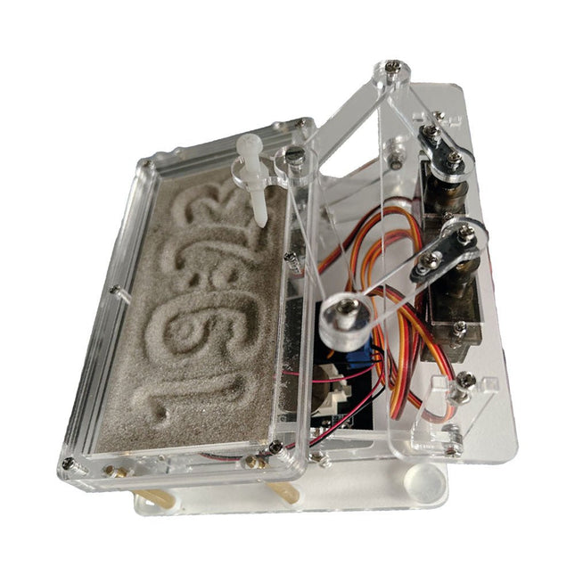
Elektor Labs Elektor Zandklok voor Raspberry Pi Pico
Een op de Raspberry Pi Pico gebaseerde Eye Catcher Een standaard zandklok laat meestal slechts zien hoe de tijd verstrijkt. Deze door een Raspberry Pi Pico aangestuurde zandklok toont daarentegen de exacte tijd door de vier cijfers voor uren en minuten in een zandlaag te "graveren". Na een vooraf ingestelde periode wordt het zand door twee trilmotoren vlak getrild en begint alles weer van voren af aan. Het hart van de zandklok wordt gevormd door twee servomotoren, die via een pantograafmechanisme een schrijfpen aandrijven. Een derde servomotor tilt deze pen op en neer. Het zandbakje is voorzien van twee trilmotoren om het zand weer vlak te trillen. Het elektronische deel van de zandklok bestaat uit een Raspberry Pi Pico en een RTC/driverbord met een real-time klok, plus drivercircuits voor de servomotoren. Een gedetailleerde bouwhandleiding is beschikbaar via download. Kenmerken Afmetingen: 135 x 110 x 80 mm Bouwtijd: ca. 1,5 tot 2 uur Inbegrepen 3x Voorgesneden acrylaatplaten met alle mechanische onderdelen 3x Mini servomotoren 2x Trilmotoren 1x Raspberry Pi Pico 1x RTC/driverkaart met geassembleerde onderdelen Moeren, boutjes, afstandhouders en draden voor de montage Fijnkorrelig wit zand
€ 49,95
Leden: € 44,96
-
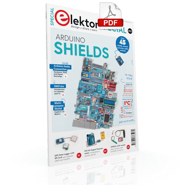
Elektor Digital Elektor Special: Arduino Shields (PDF) EN
Make your project dreams come true: an odometer for the hamster wheel, a fully automatic control of your ant farm with web interface, or the Sandwich-O-Mat – a machine that toasts and grills sandwiches of your choice. With the Arduino and the DIY or Maker movement, not only did entry into microcontroller programming become child's play, but a second development also took place: Resourceful developers brought small boards – so-called shields or modules – to the market, which greatly simplified the use of additional hardware. The small modules contain all the important electronic parts to be connected to the microcontroller with a few plug-in cables, eliminating the need for a fiddly and time-consuming assembly on the plug-in board. In addition, it is also possible to handle tiny components that do not have any connecting legs (so-called SMDs). Projects Discussed Arduino seeks connection BMP and introduction to libraries, I²C Learn I/O basics with the multi-purpose shield I²C LCD adapter and DOT matrix displays LCD keypad shield Level converter W5100: Internet connection I/O expansion shield Relays and solid-state relays The multi-function shield: A universal control unit Connecting an SD card reader via SPI Keys and 7-segment displays 16-bit ADC MCP4725 DAC 16-way PWM servo driver MP3 player GPS data logger using an SD card Touch sensor Joystick SHT31: Temperature and humidity VEML6070 UV-A sensor VL53L0X time-of-flight Ultrasonic distance meter MAX7219-based LED DOT matrix display DS3231 RTC Port expander MCP23017 433 MHz radio MPU-650 gyroscope ADXL345 accelerometer WS2812 RGB LEDs Power supply MQ-xx gas sensors CO2 gas sensor ACS712 current sensor INA219 current sensor L298 motor driver MFRC522 RFID 28BYJ-48 stepper motor TMC2209 silent step stick X9C10x digital potentiometer ST7735 in a color TFT display e-Paper display Bluetooth Geiger counter SIM800L GSM module I²C multiplexer Controller Area Network
€ 11,95
Leden: € 10,76
-

Elektor Digital Mikrocontroller-Module (PDF)
Mikrocontroller-Module (E-book)
€ 32,80
Leden: € 29,52
-

Elektor Digital Internet of Things (E-book)
The Internet of Things (IoT) is a new concept in intelligent automation and intelligent monitoring using the Internet as the communications medium. The “Things” in IoT usually refer to devices that have unique identifiers and are connected to the Internet to exchange information with each other. Such devices usually have sensors and/or actuators that can be used to collect data about their environments and to monitor and control their environments. The collected data can be processed locally or it can be sent to centralized servers or to the cloud for remote storage and processing. For example, a small device at the size of a matchbox can be used to collect data about the temperature, relative humidity and the atmospheric pressure. This data can be sent and stored in the cloud. Anyone with a mobile device can then access and monitor this data at any time and from anywhere on Earth provided there is Internet connectivity. In addition, users can for example, adjust the central heating remotely using their mobile devices and accessing the cloud. This book is written for students, for practising engineers and for hobbyists who want to learn more about the building blocks of an IoT system and also learn how to setup an IoT system using these blocks. Chapter 1 is an introduction to the IoT systems. In Chapter 2, the basic concepts and possible IoT architectures are discussed. The important parts of any IoT system are the sensors and actuators and they are described briefly in Chapter 3. The devices in an IoT system usually communicate with each other and the important aspect of IoT communication is covered in Chapter 4. Chapter 5 proceeds with the features of some of the commonly used development kits. One of these, the Clicker 2 for PIC18FJ manufactured by mikroElektronika, can be used as a processor in IoT systems and its features are described in detail in Chapter 6. A popular microcontroller C language, mikroC Pro for PIC gets introduced in Chapter 7. Chapter 8 covers the use of a click board with the Clicker 2 for PIC18FJ development kit. Similarly, the use of a sensor click board is described as a project in Chapter 9, and an actuator board in Chapter 10. Chapters 11 and 12 cover Bluetooth and Wi-Fi technologies in microcontroller based systems, and the remaining chapters of the book demo the creation of a simple Wi-Fi based IoT system with cloud-based data storage. This book has been written with the assumption that the reader has taken a course on digital logic design and has been exposed to writing programs using at least one high-level programming language. Knowledge of the C programming language will be very useful. Also, familiarity with at least one member of the PIC series of microcontrollers (e.g. PIC16 or PIC18) will be an advantage. The knowledge of assembly language programming is not required because all the projects in the book are based on using the C language. If you are a total beginner in programming you can still access the e-book, but first you are advised to study introductory books on microcontrollers.
€ 34,95
Leden: € 31,46
-

Elektor May/June 2026 (EN)
Elektor GREEN and GOLD members can download their digital edition here. Not a member yet? Click here. PbMonitor v2.0 UpdateBattery Monitoring with Improved Analog Design Audio Latency MeasurementA Standalone Tool for Evaluating Errors and Latency in Audio Transmission Square Wave vs. Bode PlotChecking the Performances of an Audio Device embedded world 2026 Clever Coding with AIAI in Software Development for Electronics Engineers QA403 Audio AnalyzerAffordable Precision for Audio Professionals and Hobbyists EasyGimbalAutonomous Camera Tracking with AI, Stepper and Servo Motors Sigfox Breakout Board (2)Sending Messages Circuit ProtectionControlling Overvoltages with TVS Diodes Emerging Battery Testing ApproachesA New Era of Diagnostics AudiotronicsA First Preamplifier CANopenTermAn Open-Source Tool That Brings CAN to Makers and Engineers Alike Stabilization of Operational AmplifiersAvoiding Feedback Instability Err-lectronicsCorrections, Updates, and Readers’ Letters Signal ConditioningTips and Tricks to Fit Voltage Ranges TDR Attachment for OscilloscopesLength, Short Circuit, Mismatch: Measure Cables Using Reflections! From Life's ExperienceLED It Be Speaker Oscillator and Resonance TesterA Fully Experimental Project for Your Speakers Elektor Community Perspectives on Test and Measurement ESP32 Audio Transceiver Board (Part 5)Audio Processing and Remote Control 2026: An AI OdysseyAI Has a Context Problem Battery Storage for Balcony Power PlantsSmall Batteries, Big Impact
€ 14,90
-
Elektor Digital Raspberry Pi Pico for Radio Amateurs (E-book)
Program and build RPi Pico-based ham station utilities, tools, and instruments Although much classical HF and mobile equipment is still in use by large numbers of amateurs, the use of computers and digital techniques has now become very popular among amateur radio operators. Nowadays, anyone can purchase a €5 Raspberry Pi Pico microcontroller board and develop many amateur radio projects using the “Pico” and some external components. This book is aimed at amateur radio enthusiasts, Electronic Engineering students, and anyone interested in learning to use the Raspberry Pi Pico to shape their electronic projects. The book is suitable for beginners in electronics as well as for those with wide experience. Step-by-step installation of the MicroPython programming environment is described. Some knowledge of the Python programming language is helpful to be able to comprehend and modify the projects given in the book. The book introduces the Raspberry Pi Pico and gives examples of many general-purpose, software-only projects that familiarize the reader with the Python programming language. In addition to the software-only projects tailored to the amateur radio operator, Chapter 6 in particular presents over 36 hardware-based projects for “hams”, including: Station mains power on/off control Radio station clock GPS based station geographical coordinates Radio station temperature and humidity Various waveform generation methods using software and hardware (DDS) Frequency counter Voltmeter / ammeter / ohmmeter / capacitance meter RF meter and RF attenuators Morse code exercisers RadioStation Click board Raspberry Pi Pico based FM radio Using Bluetooth and Wi-Fi with Raspberry Pi Pico Radio station security with RFID Audio amplifier module with rotary encoder volume control Morse decoder Using the FS1000A TX-RX modules to communicate with Arduino
€ 32,95
Leden: € 29,66
-
Elektor Digital Visual Basic for Electronics Engineering Applications (E-book)
The PC has long-time outgrown its function as a pure computer and has become an all-purpose machine. This book is targeted towards those people that want to control existing or self-built hardware from their computer. Using Visual Basic as Rapid Application Development tool we will take you on a journey to unlock the world beyond the connectors of the PC. After familiarising yourself with Visual Basic, its development environment and the toolset it offers, items such as serial communications, printer ports, bit-banging, protocol emulation, ISA, USB and Ethernet interfacing and the remote control of test-equipment over the GPIB bus, are covered in extent. Each topic is accompanied by clear, ready to run code, and where necessary, schematics are provided that will get your projects up to speed in no time. This book will show you advanced things like: using tools like Debug to find hardware addresses, setting up remote communication using TCP/IP and UDP sockets and even writing your own internet servers. Or how about connecting your own block of hardware over USB or Ethernet and controlling it from Visual Basic. Other things like internet-program communication, DDE and the new graphics interface of Windows XP are covered as well. All examples are ready to compile using Visual Basic 5.0, 6.0, NET or 2005. Extensive coverage is given on the differences between what could be called Visual Basic Classic and Visual basic .NET / 2005.
€ 39,95
Leden: € 35,96
-

Elektor Digital Elektor January/February 2021 (PDF) EN
DIY LiPo Supercharger BundleGreatScott and Elektor's LiPo Charger, Booster, and Protector MTheCamA Simple Mini Thermal Camera Weller WE 1010Soldering Station electronica Fast Forward 2020 Winners I2S Test Signal Generator with AVR Microcontroller32-Bit 1-kHz Digital Sine, fs 192 kHz, Level Adjustable from 0 to -110 dB Control Your Home with Raspberry PiRPi snoops on 433.92 MHz Simulate Circuits Online From Life's ExperienceThe Fine Line Between Order and Chaos Starting Out in ElectronicsEasier Than imagined! Homebrew CPUsThe Discrete Microcontroller Connect Your Thermostat with ESPHomeAn Attempt at Doing Home Automation the Right Way Developer’s ZoneTips & Tricks, Best Practices and Other Useful Information Small Circuits RevivalFrom the Elektor suggestions box Raspberry Pi Full StackRPi and RF24 at the heart of a sensor network Practical ESP32 Multitasking (6)Event Groups Multi-Channel Power Analyzer: Up to 3 Channels, with Graphic and Alphanumeric Display Analogue Filter Design (Part 3)Passive Filters JOY-iT VAX-1030Wireless Measurement Module New LCR Meter 50 Hz - 2 MHz Part 2Operation, Calibration, and Firmware Programming Error AnalysisTips on Voltage Regular Circuits, PCB Design, and More The Open Hardware ObservatoryCommunity-Based Open Source Hardware Assessment Java on the Raspberry PiAn Interview with Frank Delporte Data Analysis and Artificial Intelligence in PythonInterpreting Real Data with NumPy, pandas and scikit-learn Project 2.0Corrections, Updates and Readers’ letters Getting to Know the Parallax Propeller 2 (Part 1)An Introduction Hexadoku
€ 7,50
-
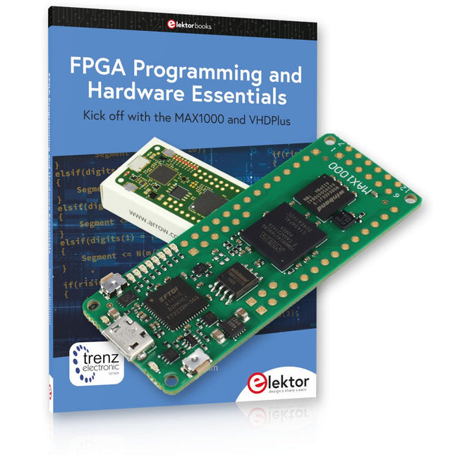
Elektor Bundles MAX1000 FPGA Programming Bundel
Begin met FPGA-programmering met het MAX1000-bord en VHDPlus Bent u klaar om FPGA-programmeren onder de knie te krijgen? Met deze bundel duikt u in de wereld van Field-Programmable Gate Arrays (FPGA's) – een configureerbaar geïntegreerd circuit dat na productie kan worden geprogrammeerd. Breng uw ideeën nu tot leven, van eenvoudige projecten tot complete microcontrollersystemen! De MAX1000 is een compact en krachtig FPGA-ontwikkelbord boordevol functies zoals geheugen, gebruikers-LED's, drukknoppen en flexibele I/O-poorten. Het is het ideale startpunt voor iedereen die meer wil weten over FPGA's en Hardware Definition Languages (HDL's). Met het bijgevoegde boek "FPGA Programming and Hardware Essentials" gaat u aan de slag met de programmeertaal VHDPlus – een eenvoudigere versie van VHDL. Je werkt aan praktische projecten met behulp van de MAX1000, waardoor je de vaardigheden en het vertrouwen krijgt om je creativiteit de vrije loop te laten. Projecten in het boek Arduino-aangedreven BCD naar 7-segment displaydecoder Gebruik een Arduino Uno R4 om BCD-gegevens aan de decoder te leveren, tel van 0 tot 9 met een vertraging van één seconde Gemultiplexte 4-cijferige gebeurtenisteller Maak een gebeurtenissenteller die het totale aantal weergeeft op een display van vier cijfers, dat bij elke druk op de knop wordt verhoogd PWM-golfvorm met vaste werkcyclus Genereer een PWM-golfvorm op 1 kHz met een vaste werkcyclus van 50% Ultrasone afstandsmeting Meet afstanden met behulp van een ultrasone sensor en geef de resultaten weer op een 4-cijferige LED met 7 segmenten Elektronisch slot Bouw een eenvoudig elektronisch slot met behulp van logische combinatiepoorten met drukknoppen en een LED-uitgang Temperatuursensor Bewaak de omgevingstemperatuur met een TMP36-sensor en geef de meetwaarden weer op een LED met 7 segmenten MAX1000 FPGA Development Board De MAX1000 is een aanpasbaar IoT/Maker Board, klaar voor evaluatie, ontwikkeling en/of gebruik in een product. Het is gebouwd rond de Intel MAX10 FPGA, het eerste niet-vluchtige programmeerbare logische apparaat (PLD's) met één chip in de sector dat de optimale set systeemcomponenten integreert. Gebruikers kunnen nu profiteren van de kracht van enorme herconfigureerbaarheid in combinatie met een krachtig FPGA-systeem met laag vermogen. MAX10-apparaten bieden intern opgeslagen dubbele beelden met zelfconfiguratie, uitgebreide ontwerpbeschermingsfuncties, geïntegreerde ADC's en hardware om de Nios II 32-bit microcontroller IP te implementeren en zijn de ideale oplossing voor systeembeheer, protocolbridging, communicatiecontrolevlakken, industriële, automobiel- en consumententoepassingen. De MAX1000 is uitgerust met een Arrow USB Programmer2, SDRAM, flashgeheugen, accelerometersensor en PMOD/Arduino MKR-connectoren, waardoor het een volledig functionele plug-and-play-oplossing is zonder extra kosten. Specificaties MAX 10 8kLE - Flash Dubbele binnenkant -ADC 8x 12-bits - Temperatuurbereik 0~85°C - Aanbod USB/pinnen SDRAM 8 MB MEMS met 3 assen LIS3DH USB-programmer aan boord MEMS-oscillator 12 MHz Schakelaar/LED 2x / 8x Inhoud van de bundel Boek: FPGA Programming and Hardware Essentials (normale prijs: € 40) MAX1000 FPGA Development Board (normale prijs: € 45) Downloads Software


