EAGLE – the “Easily Applicable Graphical Layout Editor“ is a professional-grade CAD (computer aided design) software package for the design and drafting of electronic schematics as well as the design and fabrication of printed circuit boards (PCBs).
This Advanced User Guide provides the experienced EAGLE user with insight into using some of the more advanced features of EAGLE software. It is not a guide to teach the reader the basic concepts of EAGLE, nor does it discuss the ‘how to’ of the EAGLE interface and the simpler operations and commands of the software. That is the purpose of the author’s previous title EAGLE V6 Getting Started Guide also published by Elektor.
This eBook is intended as an enduring document covering the more advanced modules, commands, and functions which make up EAGLE. It is hoped that this eBook will provide a quick, succinct reference to assist with more complex applications and uses of EAGLE – an ‘EAGLE User’s Companion’, if you like.
Complementing the EAGLE Advanced User Guide, the EAGLE User Language manual is included in this eBook in unabridged form, reproduced with permission of CadSoft GmbH.
At the time of writing, the material in this eBook covers version 7 of the EAGLE software suite.
Einführung in die SPS-Programmierung mit dem Open-Source-Projekt auf dem Raspberry Pi und Modbus-Beispiele mit dem Arduino Uno und ESP8266
Die SPS-Programmierung ist heute in der Industrie und in der Hausautomation sehr weit verbreitet. In diesem Buch beschreibt der Autor, wie der Raspberry Pi 4 als SPS eingesetzt werden kann. Angefangen mit der Softwareinstallation auf dem Raspberry Pi und dem SPS-Editor auf dem PC geht es nach einer Beschreibung der Hardware an das Programmieren.
Es folgen interessante Beispiele nach IEC 61131-3 in den verschiedenen Programmiersprachen. Ausführlich wird auch erklärt, wie der SPS-Editor benutzt wird und wie die Programme auf den Raspberry Pi geladen und ausgeführt werden. Angefangen mit der Programmierung mit KOP (Kontaktplan) über ST (Structured Control Language) bis zu AS (Special Function Chart) werden alle IEC-Sprachen mit Beispielen behandelt. Diese können auf der Website des Autors heruntergeladen werden.
Auch die Vernetzung kommt nicht zu kurz. Der Arduino Uno und der ESP8266 werden als ModbusRTU- bzw. ModbusTCP-Module programmiert, um Zugriff auf externe Peripherie zu erhalten. Damit ist es möglich, Sensoren einzulesen und Verbraucher zu schalten. Interessant dürften auch E/A-Schaltungen sein, die dem 24V-Industriestandard entsprechen.
Befehlsübersichten für ST und KOP runden das Buch ab.
Nach dem Durcharbeiten des Buches ist der Leser in der Lage, eigene SPS-Steuerungen mit dem Raspberry Pi zu verwirklichen.
De SEQURE HT140 is een zeer veelzijdige 2-in-1 soldeerbout die de functionaliteit van een hete pincet en een soldeerbout combineert. Hij is speciaal ontworpen voor nauwkeurig SMD-soldeer- en desoldeerwerk.
Met onafhankelijke regeling voor enkelzijdige verhitting werkt hij als een traditionele soldeerbout wanneer hij is uitgerust met een standaardpunt. Wanneer hij is geconfigureerd voor dubbelzijdige verhitting, transformeert hij in een hete pincet – perfect voor het efficiënt en nauwkeurig verwijderen van SMD-componenten.
Kenmerken
Werktemperatuur: 50-500°C
Ondersteunt meerdere voedingsingangen: PD 3.1/3.0/2.0, QC 3.0/2.0, (5-28 V DC), LiPo-batterijen en stroomadapters.
De HT140 combineert een soldeerpincet met een soldeerbout, met onafhankelijke enkel- of dubbelzijdige verwarming. Gebruik hem als soldeerbout met een punt, of als soldeerpincet voor eenvoudig desolderen van SMD.
Spanning en stroomsterkte kunnen worden aangepast op basis van de stroombron.
Beschikt over dubbele temperatuurregeling, voorinstellingen, snelle temperatuurverhoging en fijnafstelling.
128 x 32 OLED-scherm met instelbare helderheid en oriëntatie.
Hoognauwkeurig verwarmingselement met een nauwkeurigheid van ±1%. Smelt soldeer in slechts 2 seconden.
Slimme stand-by-, slaap- en wekfuncties verlengen de levensduur van de punt en verhogen de efficiëntie.
Ondersteunt temperatuurkalibratie en -compensatie voor nauwkeurig werk.
Inclusief een hittebestendige PD 150 W siliconenkabel van 1,5 m en een stevig, volledig metalen HT-station.
Verwisselbare punten en verstelbare hoeken voor diverse SMD-soldeertaken.
Specificaties
Werkspanning
5-28 V DC
Maximaal vermogen
140 W
Werktemperatuur
50-500°C
Smelttijd tin
2 s
Interfacetype
USB-C, DC5525
Voeding
PD 3.1/3.0/2.0, QC 3.0/2.0, 28 V DC max
Display
128 x 32 OLED
Firmware-upgrade
Ja
Menutalen
Engels, Russisch, Chinees
Afmetingen
160 x 27 x 17,5 mm
Gewicht
50 g
Inbegrepen
1x SEQURE HT140 Host
2x HT140-IS Conisch gebogen desoldeerstiften
1x HT Station
1x Accessoirepakket
1x Opbergtas
1x 65 W PD Voeding (EU, VK & VS)
1x 24 W PD Siliconen Draad (1,5 m)
1x GND Draad Accessoire Kit (1,8 m)
Downloads
Manual
Firmware V1.04
For Speed, Area, Power, and Reliability
This book teaches the fundamentals of FPGA operation, covering basic CMOS transistor theory to designing digital FPGA chips using LUTs, flip-flops, and embedded memories. Ideal for electrical engineers aiming to design large digital chips using FPGA technology.
Discover:
The inner workings of FPGA architecture and functionality.
Hardware Description Languages (HDL) like Verilog and VHDL.
The EDA tool flow for converting HDL source into a functional FPGA chip design.
Insider tips for reliable, low power, and high performance FPGA designs.
Example designs include:
Computer-to-FPGA UART serial communication.
An open-source Sump3 logic analyzer implementation.
A fully functional graphics controller.
What you need:
Digilent BASYS3 or similar FPGA eval board with an AMD/Xilinx FPGA.
Vivado EDA tool suite (available for download from AMD website free of charge).
Project source files available from author’s GitHub site.
The Basics, New Ideas & Applications
Build digital electronics from the ground up—and take it all the way to practical circuits you can use.
This book guides you through the core principles of digital technology with a strongly hands-on approach. You’ll begin with the essentials: signals, devices for working with them, and what "logic 0" and "logic 1" mean in real hardware. Simple demonstration setups made from easy-to-find parts (LEDs, diodes, resistors, switches) help you see how logic behaves, making the theory click before you move on.
From there, you’ll explore a wide range of logic elements and how they’re implemented, including classic logic families such as TTL and CMOS. The fundamentals section covers the building blocks of digital systems: flip-flops, Schmitt triggers, registers, counters and dividers, encoders/ decoders, multiplexers/demultiplexers, plus A/D and D/A conversion and timing circuits.
Next, the book invites you into "new ideas" in digital electronics—universal logic elements, unconventional approaches (including thyristor-based and fractional logic), and creative logic functions that can inspire original designs.
Finally, a large, well-organized collection of application circuits turns knowledge into projects: electronic switches and selectors, pulse generators, PWM regulators, frequency multipliers/dividers, phase shifters, and digital filters.
Study it deeply, and you’ll gain not only understanding—but the ability to design and debug digital circuits independently.
Theory, LTspice Simulation, and Hands-On Projects
MOSFETs are essential components in modern electronics, used in switching, amplification, motor control, power conversion, digital logic, and audio circuits. This book offers a practical introduction to MOSFET technology, combining clear explanations with LTspice simulations and hands-on projects.
Starting with semiconductor fundamentals, you will learn how MOSFETs operate, how they compare with BJTs, and how to apply them in real circuits. The book then progresses from basic switching applications to more advanced designs.
You will learn how to:
Understand N-channel and P-channel MOSFET operation
Work with cutoff, triode, and saturation regions
Simulate and analyze circuits using LTspice
Build switching circuits for LEDs, relays, buzzers, sensors, and motors
Create sensor circuits for light, temperature, touch, tilt, reed switches, and PIR motion detection
Control motors and fans using PWM and H-bridge circuits
Design MOSFET small-signal amplifiers
Build astable, Colpitts, Hartley, phase-shift, and Pierce oscillators
Experiment with MOSFET digital logic
Explore buck and boost DC-DC converters
Understand the basics of MOSFET audio power amplifiers
Written for engineers, students, and experienced makers, this book connects theory with simulation and practical construction, giving you the knowledge and experience to design and experiment with MOSFET circuits with confidence.
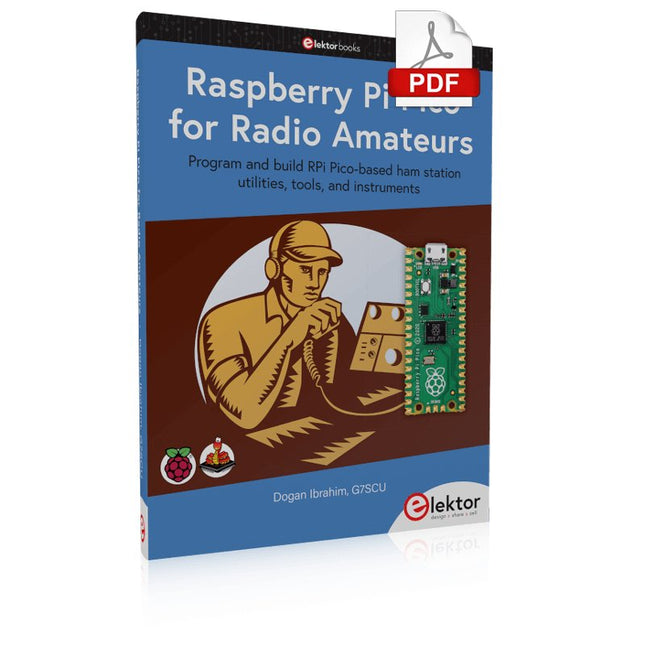
Program and build RPi Pico-based ham station utilities, tools, and instruments
Although much classical HF and mobile equipment is still in use by large numbers of amateurs, the use of computers and digital techniques has now become very popular among amateur radio operators. Nowadays, anyone can purchase a €5 Raspberry Pi Pico microcontroller board and develop many amateur radio projects using the “Pico” and some external components. This book is aimed at amateur radio enthusiasts, Electronic Engineering students, and anyone interested in learning to use the Raspberry Pi Pico to shape their electronic projects. The book is suitable for beginners in electronics as well as for those with wide experience.
Step-by-step installation of the MicroPython programming environment is described. Some knowledge of the Python programming language is helpful to be able to comprehend and modify the projects given in the book. The book introduces the Raspberry Pi Pico and gives examples of many general-purpose, software-only projects that familiarize the reader with the Python programming language. In addition to the software-only projects tailored to the amateur radio operator, Chapter 6 in particular presents over 36 hardware-based projects for “hams”, including:
Station mains power on/off control
Radio station clock
GPS based station geographical coordinates
Radio station temperature and humidity
Various waveform generation methods using software and hardware (DDS)
Frequency counter
Voltmeter / ammeter / ohmmeter / capacitance meter
RF meter and RF attenuators
Morse code exercisers
RadioStation Click board
Raspberry Pi Pico based FM radio
Using Bluetooth and Wi-Fi with Raspberry Pi Pico
Radio station security with RFID
Audio amplifier module with rotary encoder volume control
Morse decoder
Using the FS1000A TX-RX modules to communicate with Arduino
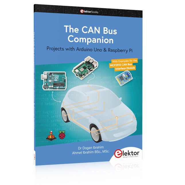
Projects with Arduino Uno & Raspberry Pi with Examples for the MCP2515 CAN Bus Interface Module
This book details the use of the Arduino Uno and the Raspberry Pi 4 in practical CAN bus based projects. Using either the Arduino Uno or the Raspberry Pi with off-the-shelf CAN bus interface modules considerably ease developing, debugging, and testing CAN bus based projects.
This book is written for students, practicing engineers, enthusiasts, and for everyone else wanting to learn more about the CAN bus and its applications. The book assumes that the reader has some knowledge of basic electronics. Knowledge of the C and Python programming languages and programming the Arduino Uno using its IDE and Raspberry Pi will be useful, especially if the reader intends to develop microcontroller-based projects using the CAN bus.
The book should be a useful source of reference material for anyone interested in finding answers to questions such as:
What bus systems are available for the automotive industry?
What are the principles of the CAN bus?
How can I create a physical CAN bus?
What types of frames (or data packets) are available in a CAN bus system?
How can errors be detected in a CAN bus system and how dependable is a CAN bus system?
What types of CAN bus controllers exist?
How do I use the MCP2515 CAN bus controller?
How do I create 2-node Arduino Uno-based CAN bus projects?
How do I create 3-node Arduino Uno-based CAN bus projects?
How do I set the acceptance masks and acceptance filters?
How do I analyze data on the CAN bus?
How do I create 2-node Raspberry Pi-based CAN bus projects?
How do I create 3-node Raspberry Pi-based CAN bus projects?
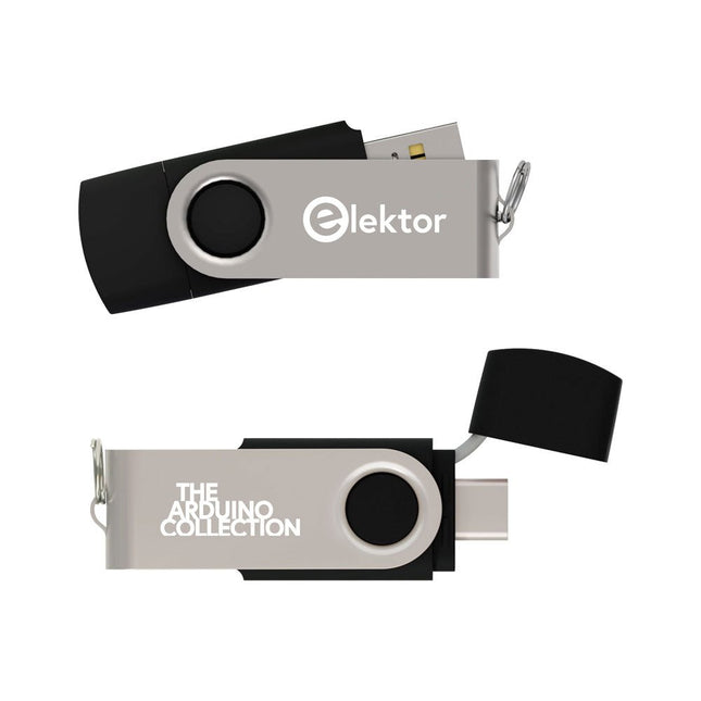
Deze USB-stick bevat een selectie van meer dan 300 artikelen over Arduino gepubliceerd in Elektor Magazine. De inhoud bestaat uit zowel achtergrondartikelen als projecten met de volgende onderwerpen:
Software & hardware ontwikkeling: Tutorials over de ontwikkeling van Arduino-software met behulp van Arduino IDE, Atmel Studio, Shields en essentiële programmeerconcepten.
Educatie: Een microcontroller Bootcamp biedt een gestructureerde aanpak voor het programmeren van embedded systemen.
Data acquisitie & meten: Projecten zoals een 16-bits datalogger, draaibank toerenteller en een AC netanalyser voor het vastleggen en analyseren van real-time signalen.
Draadloze communicatie: Leer hoe je draadloze netwerken implementeert, een Android interface maakt en effectief communiceert met microcontrollers.
Robotica en automatisering: Omvat de Arduino Nano Robot Controller, ondersteunende boards voor automatisering, en een verkenning van verschillende Arduino-shields om de functionaliteit te verbeteren.
Zelfbouw-projecten: Unieke projecten zoals laserprojectie, Numitron klok en thermometer, ELF ontvanger, Theremino, en touch LED interfaces laten creatieve toepassingen zien.
Of u nu een beginner bent of een ervaren maker, deze collectie is een waardevolle bron om te leren, te experimenteren en de grenzen van de Arduino-technologie te verleggen.
AI Projects for the Raspberry Pi with the AI HAT+
Edge AI is transforming everyday devices by putting intelligence where it matters most: directly inside the hardware. With on-device inference, a camera can recognize a visitor instantly, a phone can translate speech without streaming audio to the cloud, and a wearable can detect anomalies in real time—fast, private, and reliable even when the network disappears.
This book is your practical guide to building exactly those kinds of systems with the Raspberry Pi AI HAT+ and the Hailo-8L accelerator. You’ll start with clear foundations: core AI and machine-learning concepts, how neural networks work, and what truly distinguishes Edge AI from cloud AI—plus an honest look at ethical considerations and future impacts.
Then it’s straight to hands-on physical computing. Step by step, you’ll set up Raspberry Pi OS, power and cooling, and develop in Python using the Thonny IDE. You’ll learn GPIO basics with lights and servos, mount the AI HAT+ hardware, install and verify the Hailo software stack, and connect the right camera—official modules or USB webcams, even multiple cameras.
From your first pipeline to real projects, you’ll run person detection, pose estimation, segmentation, and depth estimation, then level up with YOLO object detection: smart alerts, guest counters, and custom extensions. You’ll even connect vision to motion by combining gesture recognition with servo-driven mechanisms, including a robotic arm.
With troubleshooting tips, hardware essentials, and a practical Python refresher, this book turns Edge AI from buzzword into buildable reality.
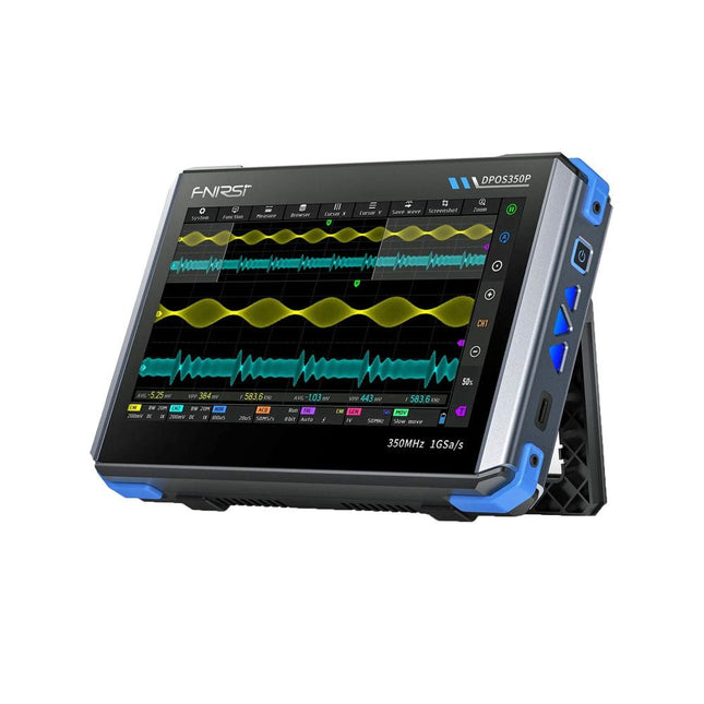
2 kanalen • 350 MHz • 1 GSa/s • 50.000 wfm/s • 7 inch Touchscreen
De FNIRSI DPOS350P is een gestroomlijnde 4-in-1 krachtpatser in tabletvorm! Dit compacte en draagbare apparaat biedt serieuze functionaliteit: het combineert een 2-kanaals oscilloscoop (350 MHz), een signaalgenerator (50 MHz), een frequentieresponsanalyzer (50 MHz) en een spectrumanalyzer (200 kHz–350 MHz) – alles in één apparaat.
Of u nu bezig bent met R&D, probleemoplossing of veldtesten, de DPOS350P biedt de tools die u nodig hebt om elektronische signalen nauwkeurig en helder te meten, genereren, analyseren en visualiseren. Het responsieve touchscreen met hoge resolutie en de intuïtieve bediening maken signaalanalyse snel, flexibel en efficiënt.
Kenmerken
Krachtige multifunctionele integratie
350 MHz 2-kanaals oscilloscoop met 1 GSa/s realtime sampling
50 MHz signaalgenerator met 14 standaard + aangepaste golfvormen
Spectrum analyzer (200 kHz–350 MHz): Perfect voor EMI, RF en HF-testen
Frequentieresponsanalyzer (FRA) tot 50 MHz
Hoogwaardige golfvormregistratie
Vernieuwingsfrequentie van 50.000 wfm/s voor realtime signaalhelderheid
Bandbreedte van 350 MHz (enkelkanaalsmodus)
Detecteert zeldzame en onwaarschijnlijke afwijkingen
Scherp display & Soepele werking
7" IPS-touchscreen (resolutie 1024 x 600)
Schakelen tussen grijstinten- en kleurtemperatuurweergave
Eenvoudig te bedienen in verschillende testomgevingen
Betrouwbaar, beveiligd en snel opladen
Hoogspanningsbeveiliging tot 400 V
Snel opladen met QC 18 W (volledig opladen in 2 uur)
Gebouwd voor stabiele, langdurige werking
Gegevensopslag en -export
Sla tot 500 golfvormrecords + 90 screenshots op
USB-export voor eenvoudige rapportage en offline analyse
Specificaties
Algemeen
Scherm
7 inch (IPS, volledige kijkhoek)
Resolutie
1024 x 600 pixels
Interactiemodus
Capacitief touchscreen
Totaal stroomverbruik
10 W
Inschakelconfiguratie
5 voorinstellingen
Opladen
QC 18 W, 12 V/1,5 A (USB-C)
Accu
3,7 V, 8000 mAh lithiumbatterij
Accuduur
ca. 3 uur in gebruik, 5 uur stand-by
Warmteafvoer
Luchtkoeling
Uitbreidingsinterface
USB-poort
Automatische uitschakeling
15 tot 60 minuten / uit
Firmware-upgrade
Ondersteunt .iso-image-upgrade
Talen
Engels / Portugees / Russisch / Chinees
Afmetingen
190 x 128 x 37 mm
Oscilloscoop
Analoge kanalen
2
Analoge bandbreedte
350 MHz
Stijgtijd
1 ns
Real-time bemonsteringsfrequentie
1 GSa/s
Geheugendiepte
60 Kpts
Ingangsimpedantie
1 MΩ / 14PF
Tijdbasisbereik
5 ns ~ 50 s
Roltijdbasis
50 ms ~ 50 s
Verticale gevoeligheid
2 mV ~ 20 V (1X)
Verticaal bereik
16 mV ~ 160 V (1X)
DC-nauwkeurigheid
±2%
Tijd nauwkeurigheid
±0,01%
Ingangskoppeling
DC / AC
Probe-verzwakking
1X / 10X / 100X
Hardwarebandbreedtelimiet
150M / 20M
Hoge-resolutiemodus
8 bit ~ 16 bit
Parametermetingen
12 typen
Cursormeting
Tijd, periode, frequentie, niveau, spanning
Triggerdetectie
Digitale trigger
Triggerkanaal
CH1 / CH2
Triggermodus
Auto / Single / Normal
Triggerflank
Rising edge / Falling edge
Triggeronderdrukking
L1 ~ L3
Triggerniveau
Handmatig / automatisch 10% ~ 90%
Screenshot-opslag
90 afbeeldingen
Golfvormopslag
500 groepen
Achtergrondraster
Weergeven/verbergen
Golfvormbeweging
Grof/fijn afstellen
Overspanningsbeveiliging
Bestandsspanning 400 V
Helderheid golfvorm
Instelbaar
Eenvoudig FFT-display
Ja
Digitale fluorescentie
Ja
Kleurtemperatuurweergave
Ja
X-Y-modus
Ja
ZOOM-tijdbasis
Ja
Automatische aanpassing met één druk op de knop
Ja
Terug naar nul met één druk op de knop
Ja
Gegevensbrowser
Ja
Signaalgenerator
Golfvormtypen
14 standaardfuncties + vastgelegde golfvorm
Frequentie
0~50 MHz (alleen sinusgolf, andere golfvormen tot 10M/5M/3M)
Amplitude
0~5 VPP
Offset
-2,5 V ~ +2,5 V
Bedrijfstype cyclus
0,1~99,9%
Frequentieresolutie
1 Hz
Amplituderesolutie
1 mV
Offsetresolutie
1 mV
Inschakelduurresolutie
0,1%
Aanpasbare vastgelegde golfvorm
500 groepen
Frequentieresponsanalyzer (FRA)
Frequentie van het excitatiesignaal
100 Hz ~ 50 MHz
Ampitude van het excitatiesignaal
0~5 VPP
Offset van het excitatiesignaal
-2,5 V ~ +2,5 V
Aantal excitatiefrequenties
20~500
Cursormeting
Frequentie / versterking / fase
Bedrijfsmodus
Enkelvoudig / cyclisch
Systeemkalibratie
Ja
Spectrumanalyzer
Conversiemethode
FFT
FFT-lengte
4K ~ 32K
Frequentiebereik
200 kHz ~ 350 MHz
Niveaubereik
-60 dBmV ~ +260 dBmV
Cursormeting
Frequentie / amplitude
Markeringsparameter
Maximale energieharmonischen
Watervalgrafiek
Ja
3D-watervalgrafiek
Ja
Automatische afstelling
Ja
Systeemkalibratie
Ja
Inbegrepen
1x FNIRSI DPOS350P (4-in-1)
2x 350 MHz-sondes
1x QC 18 W snellader (EU)
1x USB-datakabel
1x Krokodillenklem
1x Opbergtas
1x Manual
Downloads
Manual
Firmware