
Zoekresultaten voor "elektor or magazine or nl or maart or april or 2019 or pdf"
-

Elektor Digital Machine Learning mit Python für PC, Raspberry Pi und Maixduino (PDF)
Nahezu alle Menschen werden zunehmend mit den Anwendungen der „Künstlichen Intelligenz“ (KI oder AI für engl. Artificial Intelligence) konfrontiert. Musik- oder Videoempfehlungen, Navigationssysteme, Einkaufsvorschläge etc. basieren auf Verfahren, die diesem Bereich zugeordnet werden können. Der Begriff „Künstliche Intelligenz“ wurde 1956 auf einer internationalen Konferenz, dem Dartmouth Summer Research Project geprägt. Eine grundlegende Idee war dabei, die Funktionsweise des menschlichen Gehirns zu modellieren und darauf basierend fortschrittliche Computersysteme zu konstruieren. Bald sollte klar sein, wie der menschliche Verstand funktioniert. Die Übertragung auf eine Maschine wurde nur noch als ein kleiner Schritt angesehen. Diese Vorstellung erwies sich als etwas zu optimistisch. Dennoch sind die Fortschritte der modernen KI, beziehungsweise ihrem Teilgebiet dem sogenannten „Machine Learning“, nicht mehr zu übersehen. Um die Methoden des Machine Learnings näher kennenzulernen, sollen in diesem Buch mehrere verschiedene Systeme zum Einsatz kommen. Neben dem PC werden sowohl der Raspberry Pi als auch der „Maixduino“ in den einzelnen Projekten ihre Fähigkeiten beweisen. Zusätzlich zu Anwendungen wie Objekt- und Gesichtserkennung entstehen dabei auch praktisch einsetzbare Systeme wie etwa Flaschendetektoren, Personenzähler oder ein „Sprechendes Auge“. Letzteres ist in der Lage, automatisch erkannte Objekte oder Gesichter akustisch zu beschreiben. Befindet sich beispielsweise ein Fahrzeug im Sichtfeld der angeschlossenen Kamera, so wird die Information „I see a car!“ über elektronisch erzeugte Sprache ausgegeben. Derartige Geräte sind hochinteressante Beispiele dafür, wie etwa auch blinde oder stark sehbehinderte Menschen von KI-Systemen profitieren können.
€ 32,80
Leden: € 29,52
-

FNIRSI FNIRSI TMP-610S (3-in-1) Multimeter (60.000 Counts) + Oscilloscoop + Signaalgenerator
De FNIRSI TMP-610S is een compact 3-in-1 meetinstrument dat een True RMS-multimeter, een 10 MHz-oscilloscoop en een 50 kHz DDS-signaalgenerator combineert. Het apparaat is ontworpen voor het opsporen van fouten in elektronica, het testen van circuits en ontwikkelingswerkzaamheden, zowel in het laboratorium als onderweg. De multimeter biedt een resolutie van 60.000 counts en ondersteunt metingen van spanning, stroom, weerstand, capaciteit, frequentie, temperatuur, diodes en continuïteit. De geïntegreerde oscilloscoop maakt realtime golfvormanalyse mogelijk met een snelheid tot 48 MSa/s, terwijl de signaalgenerator 13 golfvormtypen ondersteunt met instelbare frequentie, amplitude en duty cycle. Dankzij een 3,5-inch IPS-touchscreen, slimme autoscan-functie, Bluetooth-connectiviteit voor DMM-functies, opslag van golfvormen, USB-exportmogelijkheid en een oplaadbare accu van 3000 mAh is de TMP-610S een veelzijdige alles-in-één-tool voor elektronicaprofessionals en hobbyisten. Kenmerken 3-in-1 ontwerp: DMM + oscilloscoop + signaalgenerator Uiterst nauwkeurige True RMS-meting (60.000 counts) 10 MHz-oscilloscoop met een samplefrequentie van 48 MSa/s Synchronisatie met Bluetooth-app (alleen multimeterfunctie) 3,5-inch slim touchscreen met diverse weergavemodi 50 kHz DDS-signaalgenerator met 13 golfvormen Ingebouwde zekering voor eenvoudige vervanging Specificaties Multimeter Functie Bereik Nauwkeurigheid DC voltage 600mV/6V/60V/600V/1000V ±(0.03%+5d) AC voltage 600mV/6V/60V /600V/750V ±(0.3%+15d) DC current 600uA/6000uA/60mA/600mA ±(0.15%+5d) 6A/10A ±(0.2%+5d) AC current 600uA/6000uA/60mA/600mA ±(0.5%+15d) 6A/10A ±(0.75%+15d) Resistance 600Ω/6KΩ/60KΩ/600KΩ/6MΩ ±(0.1%+5d) 60MΩ ±(0.2%+10d) Capacitance 60nF/600nF/6uF/60uF ±(2.5%+30d) 600uF/6mF/60mF ±(3.5%+30d Frequency 10 Hz~60 MHz ±(0.01%+5d) Temperature -40℃~1000℃ ±(1.0%+5℃) Continuity 0Ω~1KΩ ±(0.2%+5d) Diode 0V~3.0V, 0Ω~1 Ω ±(1%+5d) AC frequency response 10KHz / Oscilloscoop Real-time Sampling Rate 48 MSa/s Analog Bandwidth 10 MHz Input Impedance 1MΩ Coupling Mode AC/DC Test Voltage Range 1:1 Probe - 80Vpp (±40V) 10:1 Probe - 800Vpp (±400V) Vertical Sensitivity 10mV/div~10V/div Vertical Displacement Adjustable with indication Horizontal Time Base Range 50 ns ~ 20 s Trigger Mode Auto, Normal, Single Trigger Type Rising, Falling, 50% Trigger Level Adjustable with indication Measurement Parameters Freq, Period, +Duty, ‒Duty, +Width, ‒Width, Max, Min, P‒P, Amp, RMS, Avg Persistence Off / 500ms / 1s / ∞ Cursor Measurement Yes Waveform Screenshot Saving Yes Signaalgenerator Output Waveform Supports 13 waveform types Frequency 0~50kHz Amplitude 0.0V~3.0V Duty Cycle 0~100%, adjustable for Square and Sawtooth waves Inbegrepen 1x FNIRSI TMP-610S multimeter + oscilloscoop + signaalgenerator 1x P6100-sonde 1x Adapter 2x Krokodillenklemmen 2x Multimetersondes Probe-accessoires 1x Opbergtas 1x USB-C kabel 1x Manual Downloads Manual
€ 179,95€ 149,95Beste prijs
-

Elektor Publishing Experimenting with Red Pitaya STEMlab Gen 2
Practical Projects and Programs With Experimenting with Red Pitaya STEMlab Gen 2, Red Pitaya goes beyond a versatile board. It becomes a powerful laboratory instrument for precision measurement, analysis, and control. From the fundamentals of electronic project development, monitoring, control, and design to testing, this book walks you step-by-step through everything you need to know to harness the full potential of Red Pitaya hardware and software. The book presents real-time, FPGA-based projects that are developed on a PC using the Vivado environment, then transferred to the Red Pitaya for execution and testing. You will learn about enhanced performance, expanded I/O capabilities, improved FPGA features, and advanced connectivity options that open up new frontiers for precision measurement, monitoring, and control in your embedded applications. Inside the book you will discover: A deep dive into Red Pitaya architecture and hardware design Electronic experiments using Red Pitaya for measurement and monitoring Hands-on projects using the Python programming language Practical guidance for FPGA programming using Red Pitaya Red Pitaya FPGA projects using the Verilog HDL under Vivado IDE Practical design of electronic projects including measurement and testing Step-by-step examples that bridge theory and real-world implementation Whether you are designing your own electronic circuits, developing signal analysis tools, or creating real-time control or monitoring systems, this book provides you the knowledge and confidence you need to fully learn and customize the Red Pitaya platform.
€ 39,95€ 32,95Beste prijs
-

Raspberry Pi Foundation Le guide officiel du débutant Raspberry Pi (5ème édition)
Entièrement mise à jour pour le Raspberry Pi 5 Raspberry Pi 5 est un petit ordinateur intelligent, de construction britannique qui regorge de potentiel. Fabriqué à l'aide d'un processeur économe en énergie, le Raspberry Pi est conçu pour vous aider à apprendre le codage, découvrir comment fonctionne un ordinateur et construire vos propres projets uniques et incroyables. Ce guide est conçu pour vous montrer à quel point il est facile de démarrer. Apprendre à : Configurez votre Raspberry Pi, installez son système d'exploitation, et commencez à utiliser cet ordinateur entièrement fonctionnel. Commencez à coder des projets, avec des guides étape par étape utilisant les langages de programmation Scratch 3, Python et MicroPython. Expérimentez en connectant des composants électroniques, et amusez-vous à créer des projets incroyables. Nouveauté de la 5ème édition : Mise à jour pour les derniers ordinateurs Raspberry Pi : Raspberry Pi 5 et Raspberry Pi Zèro 2 W. Couvre le dernier système d'exploitation Raspberry Pi. Comprend un nouveau chapitre sur le Raspberry Pi Pico ! Téléchargements GitHub
€ 24,95€ 9,95Beste prijs
-
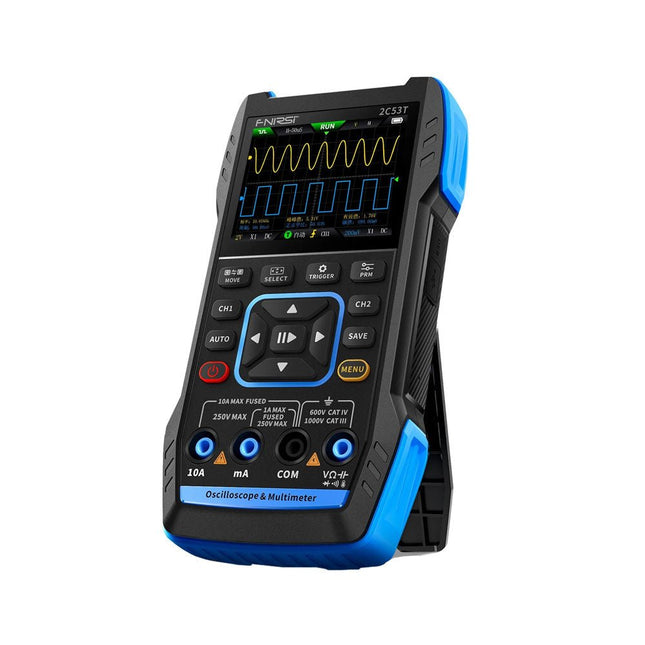
FNIRSI FNIRSI 2C53T (3-in-1) 2-kanaals Oscilloscoop (50 MHz) + Multimeter + Signaalgenerator
De FNIRSI 2C53T, een verbeterde versie van zijn 10 MHz voorganger, is een compact en veelzijdig 3-in-1 apparaat. Het combineert een tweekanaals 50 MHz-oscilloscoop, een 4,5-cijferige True RMS-multimeter en een signaalgenerator met 13 golfvormtypen, waardoor het een essentieel hulpmiddel is voor onderhouds- en onderzoeksprofessionals. Oscilloscoop: beschikt over een bandbreedte van 50 MHz, een bemonsteringssnelheid van 250 MS/s, ±400 V-bescherming, FPGA + ARM + ADC-architectuur en opslag van golfvormen voor analyse. Multimeter: 4,5-cijferig True RMS met 19999 counts, ondersteunt AC/DC-spannings-, stroom-, capaciteits-, weerstands-, diode- en continuïteitsmetingen. Signaalgenerator: voert 13 signaaltypen uit tot 50 kHz, met instelbare frequentie, amplitude en werkcyclus. Met een 2,8-inch LCD-scherm, een batterij van 3000 mAh (6 uur looptijd) en een draagbaar ontwerp biedt hij krachtige functionaliteit in een gebruiksvriendelijk pakket. Specificaties Oscilloscoop Kanalen 2 Analoge bandbreedte 50 MHz Realtime sampling rate 250 MS/s Opslagdiepte 1 Kpts Impedantie 1 MΩ Tijdbasisbereik 10ns-20s Verticale gevoeligheid 10 mV/div-10 V/div (x1) Maximum gemeten spanning ±400 V Triggermodus Auto/Normal/Single Triggertype Rising edge, Falling edge Weergavemodus Y-T/Rolling/X-Y Koppelingsmethode AC/DC Persistentie UIT, 500ms, 1s, ∞ Wiskunde 8 Basisbewerkingen + FFT Ondersteund Screenshot golfvorm opslaan, golfvormafbeelding exporteren, cursormeting, oneindig nagloeien Multimeter Gelijkspanning 1.9999V/19.999V/199.99V/1000V ±(0.5%+3) AC-spanning 1.9999V/19.999V/199.99V/750.0V ±(1%+3) Gelijkstroom 19.999mA/199.99mA/1.9999A/9.999A ±(1.2%+3) AC-stroom 19.999mA/199.99mA/1.9999A/9.999A ±(1.5%+3) Weerstand 19.999MΩ/1.9999MΩ/199.99KΩ/19.999KΩ ±(0.5%+3) 1.9999KΩ/199.99Ω ±(2.0%+3) Capaciteit 999.9uF/99.99uF/9.999uF/999.9nF/99.99nF/9.999nF ±(2.0%+5) 9.999mF/99.99mF ±(5.0%+20) Temperatuur −55~1300°C ±(2.5%+5) Continuïteitstest Ja Diode Ja Signaalgenerator 13 signaalgolfvormen Sinusgolf, rechthoekige golf, zaagtandgolf, halve golf, volledige golf, positieve stapgolf, omgekeerde stapgolf, exponentiële stijging, exponentiële daling, DC, multi-audio, zinkloodpuls, Lorentz-golf Uitgangsfrequentie 0-50 KHz Uitgangsamplitude 0-3 V Uitgangscyclus 0-100% Algemeen Weergave 2,8" HD-kleurenscherm Resolutie 320 x 240 Opladen USB-C (5 V/1 A) Batterij 3000 mAh lithiumbatterij Stand-by tijd 6 uur Talen Engels, Chinees Afmetingen 167 x 89 x 35 mm Gewicht 300 g Verschillen nieuwe versus oude versie Model 2C53T Upgrade 2C53T Voorganger Bandbreedte 50 MHz 10 MHz Weergavemodus Y-T/Rolling/X-Y Y-T/Rolling Wiskunde 8 basisbewerkingen + FFT N.v.t. Cursorfunctie Ja N.v.t. XY Lissau-grafiek Ja N.v.t. Nagloeifunctie Ja N.v.t. Multimeter-nauwkeurigheid 19999 Counts 9999 Counts Signaalgenerator 50 KHz 2 MHz Inbegrepen 1x FNIRSI 2C53T Oscilloscoop (50 MHz) 2x P6100-oscilloscoopsondes (10X) 1x Multimetersonde 1x Krokodillenklemsonde 1x USB-C-oplaadkabel 1x Opbergtas 1x Manual Downloads Manual Firmware V1.2.0
€ 119,95€ 94,95Beste prijs
-

Elektor Digital AVR-Mikrocontroller (PDF)
Programmierung in Assembler und C am Beispiel der ATtiny-Familie Dieses Buch bietet einen eingehenden Blick auf die 8-Bit-AVR-Architektur in ATtiny- und ATmega-Mikrocontrollern, hauptsächlich aus der Sicht der Software und der Programmierung. Erforschen Sie die AVR-Architektur unter Verwendung von C und Assembler in Microchip Studio (früher Atmel Studio) mit ATtiny-Mikrocontrollern. Lernen Sie die Details der internen Funktionsweise von AVR-Mikrocontrollern kennen, einschließlich der internen Register und des Speicherplans von ATtiny-Bausteinen. Programmieren Sie ATtiny-Mikrocontroller mit einem Atmel-ICE-Programmiergerät/Debugger oder verwenden Sie ein preiswertes Hobby-Programmiergerät oder sogar einen Arduino Uno als Programmiergerät. Die meisten Code-Beispiele können mit dem Microchip Studio AVR-Simulator ausgeführt werden. Lernen Sie, Programme für ATtiny-Mikrocontroller in Assembler zu schreiben. Erfahren Sie, wie Assemblersprache in Maschinencodebefehle umgewandelt wird. Finden Sie heraus, wie Programme, die in der Programmiersprache C geschrieben wurden, in Assemblersprache und schließlich in Maschinencode umgewandelt werden. Verwenden Sie den Microchip Studio Debugger in Kombination mit einem Hardware-USB-Programmierer/Debugger, um Assembler- und C-Programme zu testen oder verwenden Sie den Microchip Studio AVR-Simulator. ATtiny-Mikrocontroller im DIP-Gehäuse werden verwendet, um eine einfache Nutzung auf Breadboards zu ermöglichen. Erfahren Sie mehr über Timing und Taktimpuls in AVR-Mikrocontrollern mit ATtiny-Bausteinen. Werden Sie zu einem AVR-Experten mit fortgeschrittenen Debugging- und Programmierfähigkeiten.
€ 32,80
Leden: € 29,52
-
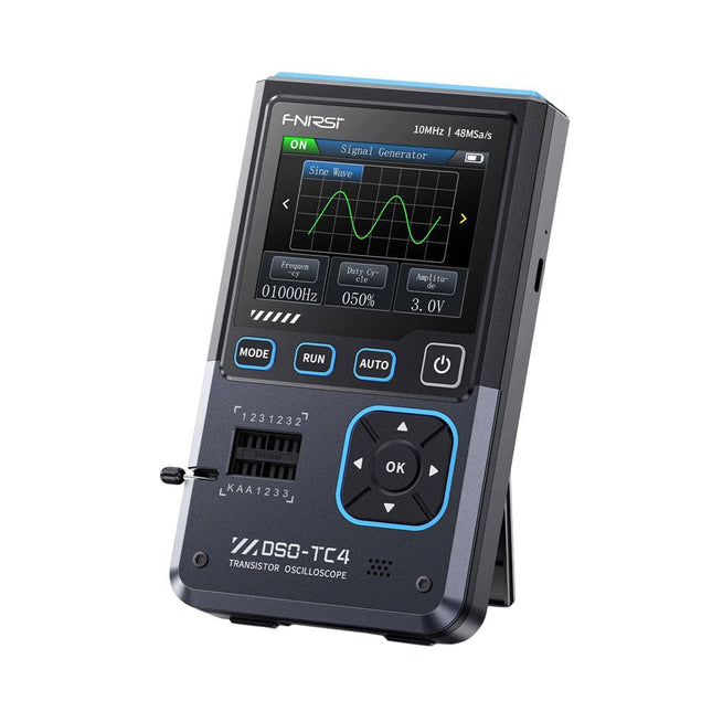
FNIRSI FNIRSI DSO-TC4 (3-in-1) Oscilloscoop (10 MHz) + Transistortester + Signaalgenerator
De FNIRDSI DSO-TC4 is een multifunctionele transistor-oscilloscoop die zowel uitgebreid als praktisch is. Het is ontworpen voor gebruik in onderhouds- en R&D-toepassingen, waarbij een oscilloscoop, transistortester en signaalgenerator in één apparaat worden geïntegreerd. Kenmerken Uitgerust met een 2,8-inch TFT-kleurenscherm voor een helder en intuïtief display Ingebouwde oplaadbare lithiumbatterij met hoge capaciteit (1500 mAh) met een stand-bytijd van maximaal 4 uur Compact en lichtgewicht, ideaal voor mobiel gebruik Specificaties Oscilloscoop Analoge bandbreedte 10 MHz Real-time bemonsteringsfrequentie 48 MSa/s Ingangsimpedantie 1 MΩ Koppelingsmodus AC/DC Testspanningsbereik 1:1-sonde: 80 Vpp (+40 V) 10:1 Sonde: 800 Vpp (+400 V) Verticale gevoeligheid 10 mV/div~10 V/div (X1-bereik) Verticale verplaatsing Instelbaar met indicatie Tijdbasisbereik 50ns~20s Triggermodus Auto/Normal/Single Triggertype Rising edge, Falling edge Triggerniveau Instelbaar met indicatie Waveform Freeze Ja (HOLD-functie) Automatische meting Max, Min, Avg, RMS, Vpp, Frequency, Cycle, Duty Cycle Transistortester Transistor Versterkingsfactor "hfe"; Basis-emitterspanning "Ube", Ic/Ie, collector-emitter omgekeerde lekstroom "Iceo", Ices, voorwaartse spanningsval van beschermingsdiode "Uf" Diode Voorwaartse spanningsval <5 V (voorwaartse spanningsval, junctiecapaciteit, omgekeerde lekstroom) Zenerdiode 0,01~32 V Omgekeerde doorslagspanning (K-A-A-testgebied) Veldeffecttransistor (FET) JFET: Gatecapaciteit "Cg", Drainstroom Id onder "Vgs", voorwaartse spanningsval van beschermingsdiode "Uf" IGBT: Drainstroom Id onder Vgs, Voorwaartse spanningsval van beschermingsdiode Uf MIOSTET: Drempelspanning "Vt", Gatecapaciteit "Cg", Drain-Sourceweerstand "Rds", Voorwaartse spanningsval van beschermingsdiode "Uf" Unidirectionele SCR Triggerspanning <5V, Gateniveau (Gatespanning) Bidirectionele SCR Triggerstroom <6mA (Gatespanning) Condensator 25pF~100mF, Capaciteitswaarde, Verliesfactor "Vloss" Weerstand 0,01Ω~50MΩ Inductor 10μH~1000μH, DC-weerstand DS18B20 Temperatuursensor, pinnen: GND, DQ, VDD DHT11 Temperatuur- en vochtigheidssensor, pinnen: VDD, DATA, GND Signaalgenerator Uitgangsgolfvorm Ondersteunt 13 golfvormuitgangen Golfvormfrequentie 0-50 KHz Vierkante golf-inschakelduur 0-100% Golfvormamplitude 0,1-3,0 V Algemeen 2,8-inch TFT-kleurenscherm Achtergrondverlichting Helderheid instelbaar Voeding USB-C (5 V/1 A) Batterij 3,7 V/1500 mAh Talen Engels, Duits, Spaans, Portugees, Russisch, Chinees, Japans, Koreaans Afmetingen 90 x 142 x 27,5 mm Gewicht 186 g Inbegrepen 1x FNIRSI DSO-TC4 (3-in-1) Oscilloscoop (10 MHz) 1x P6100-oscilloscoopsonde (10X) 1x Krokodillenklemsonde 3x Testhaken 1x Adapter 1x USB-C-oplaadkabel 1x Manual Downloads Manual Firmware V0.0.7 (+V1.0.9)
€ 89,95€ 74,95Beste prijs
-

Elektor Digital RISC-V Assembly Language Programming using ESP32-C3 and QEMU (E-book)
With the availability of free and open source C/C++ compilers today, you might wonder why someone would be interested in assembler language. What is so compelling about the RISC-V Instruction Set Architecture (ISA)? How does RISC-V differ from existing architectures? And most importantly, how do we gain experience with the RISC-V without a major investment? Is there affordable hardware available? The availability of the Espressif ESP32-C3 chip provides a way to get hands-on experience with RISC-V. The open sourced QEMU emulator adds a 64-bit experience in RISC-V under Linux. These are just two ways for the student and enthusiast alike to explore RISC-V in this book. The projects in this book are boiled down to the barest essentials to keep the assembly language concepts clear and simple. In this manner you will have “aha!” moments rather than puzzling about something difficult. The focus in this book is about learning how to write RISC-V assembly language code without getting bogged down. As you work your way through this tutorial, you’ll build up small demonstration programs to be run and tested. Often the result is some simple printed messages to prove a concept. Once you’ve mastered these basic concepts, you will be well equipped to apply assembly language in larger projects.
€ 34,95
Leden: € 31,46
-
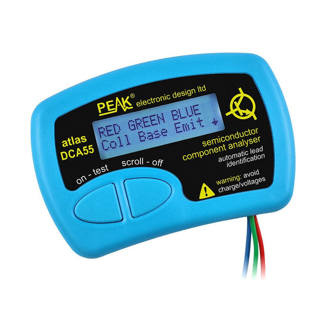
Peak Peak Atlas DCA55 Semiconductor Analyzer
The Peak Atlas DCA55 is great for automatically identifying the type of semiconductor on the test leads as well as the pinout and many other parameters. Supports transistors MOSFETs, JFETs (gate pin only can be identified), diodes, LEDs and lots more. Automatically identifies type of component, pinout and other important parameters. Now features transistor leakage measurement and Germanium/Silicon identification. Component Support Bipolar transistors (NPN/PNP inc Silicon/Germanium) Darlington transistors (NPN/PNP) Enhancement mode MOSFETs (N-Ch and P-Ch) Depletion mode MOSFETs (N-Ch and P-Ch) Junction FETs (N-Ch and P-Ch). Only gate lead identified. Diodes and diode networks (2 and 3 lead types). LEDs and bi-colour LEDs (2 lead and 3 lead types). Low power sensitive Triacs and Thyristors (<5 mA trigger and hold) Measurements Part type identification Pinout identification BJT current gain (hFE) BJT base emitter voltage (Vbe) BJT collector leakage current MOSFET gate threshold voltage Diode forward voltage drop (Vf) Specificaties Analyzer type Transistors, Diodes, LEDs, MOSFETs, JFETs Pinout detection Full pinout (only Gate on JFETs) Pinout configuration Connect any way round Transistor measurements Vbe, hFE, Iceo MOSFET measurements Vgs(on) Diode measurements Vf Probe type Universal grabber type Battery Single AAA cell (supplied). Life typically 1300 ops Test conditions Typically 5 mA, 5 V peak Display type Alphanumeric LCD (with backlight) Inbegrepen DCA55 Semiconductor Component Analyser instrument Comprehensive illustrated user guide Fitted universal hook probes AAA Alkaline battery Downloads Datasheet (EN) User Guide (EN)
€ 83,49
-
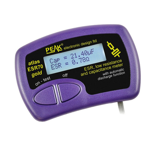
Peak Peak Atlas ESR70 gold (ESR- en capaciteitsmeter)
The Peak Atlas ESR70 gold is an enhanced version of the previous Peak Atlas ESR70 Plus. It does everything that the ESR70 Plus did but better. It now measures capacitance up to 10x faster, and over a wider range, thanks to new test algorithms. The capacitance measurement is also much less influenced by parallel resistances or leakage current thanks to our new Triple-Slope measurement system. Using the supplied gold plated probes (removable), the Atlas ESR70 gold can measure ESR down to a resolution of 0.01 ohms, up to 40 ohms. It can even measure ESR for capacitors that are in-circuit. Probes are removable, allowing 2 mm compatible probes to be fitted. Audible alerts are produced for various ESR levels allowing you to perform many tests in succession without having to look at the display. The ESR70 automatically takes capacitive reactance into account, so even low value capacitors (down to 0.3 uF) can have the ESR measured accurately. Kenmerken Uses a single AAA Alkaline cell (included). Alphanumeric LCD with backlight. Automatic analysis-start when you apply the probes. Automatic capacitor discharge using controlled discharge function. ESR (and low DC resistance) measurement (even in-circuit). Capacitive reactance automatically taken into account to ensure accurate ESR. Capacitance measurement (if testing out-of-circuit). Audible alerts for various ESR levels. Extended ESR measurement range up to 40 Ohms. Optional probe alternatives easily fitted. New gold Features Improved LCD with better backlight. 10x faster capacitance measurement for large capacitors. Enhanced user options system. New triple-slope measurement system to vastly reduce the influence of parallel resistance and/or leakage current on capacitance measurements. Much wider capacitance measurement range now 0.3 uF to 90,000 uF (was 1uF to 22,000uF). Specificaties Analyzer type ESR and Capacitance Component types Capacitors (>0.3 uF) ESR range 0.00 Ohms to 40.0 Ohms ESR resolution From 0.01 Ohms In-circuit use ESR only Capacitance range 0.3 uF to 90000 uF Battery type 1.5 V Alkaline AAA Cell (supplied). Life typically 1500 ops Display type Alphanumeric LCD (with backlight) Inbegrepen Peak Atlas ESR70 gold Extra-long and extra-flexible test cables (450 mm of Silicone covered cable) 2 mm gold plated plugs and sockets with removeable gold plated crocodile clips Comprehensive illustrated user guide AAA Alkaline cell Downloads Datasheet (EN) User Guide (EN)
€ 143,99
-

Elektor Digital Explore ATtiny Microcontrollers using C and Assembly Language (E-book)
AVR Architecture and Programming An in-depth look at the 8-bit AVR architecture found in ATtiny and ATmega microcontrollers, mainly from a software and programming point of view. Explore the AVR architecture using C and assembly language in Microchip Studio (formerly Atmel Studio) with ATtiny microcontrollers. Learn the details of how AVR microcontrollers work internally, including the internal registers and memory map of ATtiny devices. Program ATtiny microcontrollers using an Atmel-ICE programmer/debugger, or use a cheap hobby programmer, or even an Arduino Uno as a programmer. Most code examples can be run using the Microchip Studio AVR simulator. Learn to write programs for ATtiny microcontrollers in assembly language. See how assembly language is converted to machine code instructions by the assembler program. Find out how programs written in the C programming language end up as assembly language and finally as machine code instructions. Use the Microchip Studio debugger in combination with a hardware USB programmer/debugger to test assembly and C language programs, or use the Microchip Studio AVR simulator. DIP packaged ATtiny microcontrollers are used in this volume for easy use on electronic breadboards, targeting mainly the ATtiny13(A) and ATtiny25/45/85. Learn about instruction timing and clocks in AVR microcontrollers using ATtiny devices. Be on your way to becoming an AVR expert with advanced debugging and programming skills.
€ 34,95
Leden: € 31,46
-

Elektor Digital ESP8266 and MicroPython (E-book)
Recently, the development of a tiny chip called the ESP8266 has made it possible to interface any type of microcontroller to a Wi-Fi AP. The ESP8266 is a low-cost tiny Wi-Fi chip having fully built-in TCP/IP stack and a 32-bit microcontroller unit. This chip, produced by Shanghai based Chinese manufacturer Espressif System, is IEEE 802.11 b/g/n Wi-Fi compatible with on-chip program and data memory, and general purpose input-output ports. Several manufacturers have incorporated the ESP8266 chip in their hardware products (e.g. ESP-xx, NodeMCU etc) and offer these products as a means of connecting a microcontroller system such as the Android, PIC microcontroller or others to a Wi-Fi. The ESP8266 is a low-power chip and costs only a few Dollars. ESP8266 and MicroPython – Coding Cool Stuff is an introduction to the ESP8266 chip and describes the features of this chip and shows how various firmware and programming languages such as the MicroPython can be uploaded to the chip. The main aim of the book is to teach the readers how to use the MicroPython programming language on ESP8266 based hardware, especially on the NodeMCU. Several interesting and useful projects are given in the e-book (pdf) to show how to use the MicroPython in NodeMCU type ESP8266 hardware: Project “What shall I wear today?”: You will be developing a weather information system using a NodeMCU development board together with a Text-to-Speech processor module. Project “The Temperature and Humidity on the Cloud”: You will be developing a system that will get the ambient temperature and humidity using a sensor and then store this data on the cloud so that it can be accessed from anywhere. Project “Remote Web Based Control”: You will be developing a system that will remotely control two LEDs connected to a NodeMCU development board using an HTTP Web Server application.
€ 29,95
Leden: € 26,96


