
Zoekresultaten voor "fahrzeugdiagnose OR mit OR obd OR 2"
-

Elektor Digital SPS-Programmierung mit dem Raspberry Pi und dem OpenPLC-Projekt (PDF)
Einführung in die SPS-Programmierung mit dem Open-Source-Projekt auf dem Raspberry Pi und Modbus-Beispiele mit dem Arduino Uno und ESP8266 Die SPS-Programmierung ist heute in der Industrie und in der Hausautomation sehr weit verbreitet. In diesem Buch beschreibt der Autor, wie der Raspberry Pi 4 als SPS eingesetzt werden kann. Angefangen mit der Softwareinstallation auf dem Raspberry Pi und dem SPS-Editor auf dem PC geht es nach einer Beschreibung der Hardware an das Programmieren. Es folgen interessante Beispiele nach IEC 61131-3 in den verschiedenen Programmiersprachen. Ausführlich wird auch erklärt, wie der SPS-Editor benutzt wird und wie die Programme auf den Raspberry Pi geladen und ausgeführt werden. Angefangen mit der Programmierung mit KOP (Kontaktplan) über ST (Structured Control Language) bis zu AS (Special Function Chart) werden alle IEC-Sprachen mit Beispielen behandelt. Diese können auf der Website des Autors heruntergeladen werden. Auch die Vernetzung kommt nicht zu kurz. Der Arduino Uno und der ESP8266 werden als ModbusRTU- bzw. ModbusTCP-Module programmiert, um Zugriff auf externe Peripherie zu erhalten. Damit ist es möglich, Sensoren einzulesen und Verbraucher zu schalten. Interessant dürften auch E/A-Schaltungen sein, die dem 24V-Industriestandard entsprechen. Befehlsübersichten für ST und KOP runden das Buch ab. Nach dem Durcharbeiten des Buches ist der Leser in der Lage, eigene SPS-Steuerungen mit dem Raspberry Pi zu verwirklichen.
€ 32,80
Leden: € 29,52
-

Elektor Publishing Logic Analyzer im Einsatz
USB-Logikanalysatoren am PC mit Arduino, Raspberry Pi und Co Schritt-für-Schritt-Anleitungen führen Sie in die Analyse moderner Protokolle von I²C, SPI, UART, RS-232, NeoPixel, WS28xx, HD44780 und 1-Wire ein. Anhand von zahlreichen Experimentierschaltungen mit dem Raspberry Pi Pico, Arduino Uno und dem Bus Pirate üben Sie die praxisnahe Anwendung gängiger USB-Logikanalysatoren ein. Alle in diesem Buch vorgestellten Experimentierschaltungen wurden vollständig getestet und sind funktionsfähig. Die notwendigen Programmlistings sind enthalten, es sind keine besonderen Programmier- oder Elektronikkenntnisse für diese Schaltungen notwendig. Es werden die Programmiersprachen MicroPython und C mit den Entwicklungsumgebungen Thonny und Arduino IDE eingesetzt. Dieses Buch verwendet mehrere Modelle flexibler und weit verbreiteter USB-Logikanalysatoren und zeigt die Stärken und Schwächen jeder Preisklasse. Sie werden kennenlernen, welche Kriterien für Ihre Arbeit wichtig sind und in der Lage sein, das für Sie passende Gerät zu finden. Egal ob Arduino, Raspberry Pi oder Raspberry Pi Pico: Die abgebildeten Beispielschaltungen ermöglichen einen schnellen Start in die Protokollanalyse und können auch als Grundlage für eigene weitere Experimente dienen. Sie werden alle wichtigen Begriffe und Zusammenhänge kennenlernen, eigene Experimente durchführen, selbstständig Protokolle analysieren und nach der Lektüre dieses Buches – im Bereich der digitalen Signale und Protokolle – ein umfassendes Wissen aufgebaut haben.
€ 39,80
Beste prijs
-
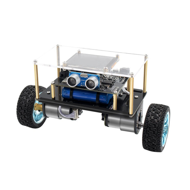
Elektor Labs Elektor Mini-Wheelie zelfbalancerende Robot
Arduino-compatibele, ESP32-aangedreven tweewielige balansrobot De Elektor Mini-Wheelie is een experimenteel autonoom zelfbalancerend robotplatform. De zelfbalancerende robot is gebaseerd op een ESP32-S3-microcontroller en is volledig programmeerbaar met behulp van de Arduino-omgeving en open-sourcebibliotheken. Dankzij de draadloze mogelijkheden kan hij op afstand worden bediend via Wi-Fi, Bluetooth of ESP-NOW, of kan hij communiceren met een gebruiker of zelfs een andere robot. Er is een ultrasone transducer beschikbaar voor het detecteren van obstakels. Het kleurendisplay kan worden gebruikt voor het weergeven van schattige gezichtsuitdrukkingen of, voor de meer nuchtere gebruikers, voor cryptische debug-berichten. De robot wordt geleverd als een compleet bouwpakket met onderdelen die u zelf in elkaar moet zetten. Alles zit erbij, zelfs een schroevendraaier. Let op: De Mini-Wheelie is een educatief ontwikkelingsplatform bedoeld voor leren, experimenteren en robotica-ontwikkeling. Het is niet geclassificeerd als speelgoed voor kinderen en de functies, documentatie en beoogde doelgroep weerspiegelen dit doel. Het product is gericht op studenten, docenten en ontwikkelaars die robotica, programmeren en hardware-integratie willen verkennen in een educatieve omgeving. Specificaties ESP32-S3-microcontroller met Wi-Fi en Bluetooth MPU6050 6-assige Inertial Measurement Unit (IMU) Twee onafhankelijk geregelde 12 V elektromotoren met toerenteller Ultrasone transducer 2,9" TFT-kleurendisplay (320 x 240) MicroSD-kaartsleuf Batterijstroommonitor 3S oplaadbare Li-Po-batterij (11,1 V/2200 mAh) Batterijlader meegeleverd Op Arduino gebaseerde open source-software Afmetingen (B x L x H): 23 x 8 x 13 cm Inbegrepen 1x ESP32-S3 Mainboard + MPU6050 module 1x LCD-board (2,9 inch) 1x Ultrasone-sensor 1x Batterijpakket (2200 mAh) 1x Batterijlader 1x Motorbandenset 1x Kastboard 1x Acrylplaat 1x Schroevendraaier 1x Beschermstrip 1x Flexkabel B (8 cm) 1x Flexkabel A (12 cm) 1x Flexkabel C 4x Koperen kolom A (25 mm) 4x Koperen kolom B (55 mm) 4x Koperen kolom C (5 mm) 2x Kunststof nylon zuil 8x Schroeven A (10 mm) 24x Schroeven B (M3x5) 8x Moeren 24x Metalen ringen 2x Ritssluiting 1x MicroSD-kaart (32 GB) Downloads Documentation
€ 89,95
Leden: € 80,96
-
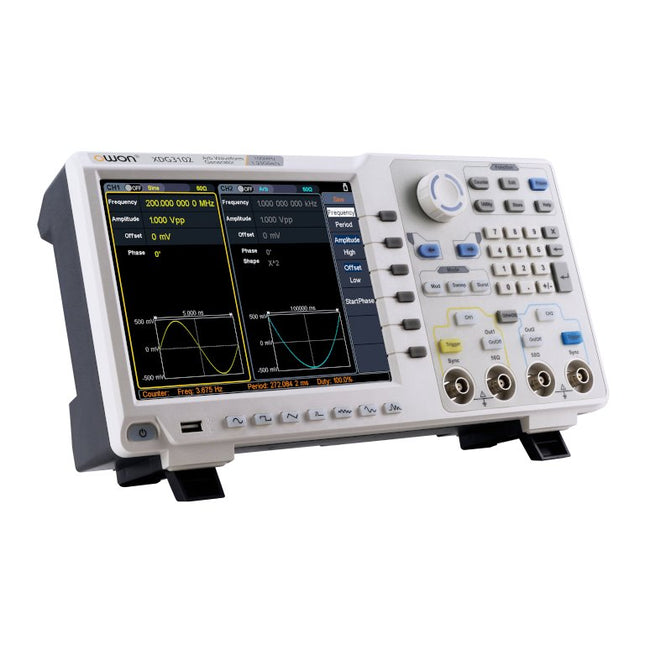
OWON OWON XDG3102 2-kanaals Arbitrary Waveform Generator (100 MHz)
Kenmerken Advanced DDS technology, up to 250MHz frequency output 1.25GS/s sampling rate, and 1 μHz frequency resolution Up to 1M arbitrary waveform length Vertical resolution: 14 bits Comprehensive waveform output: 6 groups waveforms, and 152 group built-in arbitrary waveforms Comprehensive modulation options: AM, FM, PM, FSK, 3FSK, 4FSK, PSK, OSK, ASK, BPSK, PWM, sweep, and burst High-accuracy frequency counter integrated, ranging from 100mHz till 200MHz SCPI and LabVIEW supported 8'' 800 x 600 pixels touch screen LCD Specificaties XDG3102 Channel 2 Frequency Output 100MHz Sample Rate 1.25GSa/s Vertical Resolution 14 bits Waveform Standard Waveform sine, square, pulse, ramp, noise, and harmonic Arbitrary Waveform exponential rise, exponential fall, sin(x)/x, step wave, and others, total of 150 built-in waveforms, and user-defined arbitrary waveform Frequency (resolution 1μHz) Sine 1μHz - 100MHz Square 1μHz - 40MHz Pulse 1μHz - 25MHz Ramp 1μHz - 5MHz Harmonic 1μHz - 50MHz Noise 120MHz (-3dB, typical) Arbitrary Waveform built-in waveform: 1uHz - 15MHzuser-defined waveform: 1uHz - 50MHz Accuracy ±1ppm, 0°C - 40°C Amplitude Amplitude (50Ω) 1mVpp - 10Vpp (≤40MHz); 1mVpp - 5Vpp (≤80MHz) 1mVpp - 2.5Vpp (≤120MHz); 1mVpp - 1Vpp (≤250MHz) Amplitude(high impedance) 2mVpp - 20Vpp (≤40MHz); 2mVpp - 10Vpp (≤80MHz); 2mVpp - 5Vpp (≤120MHz); 2mVpp - 2Vpp (≤250MHz) Resolution 1mV or 4 digits DC Offset Range (50Ω) ±(5 Vpk - Amplitude Vpp/2) Range (high-Z, open circuit) ±(10 Vpk - Amplitude Vpp/2) Accuracy ±(1% of |setting| + 1mV + Amplitude Vpp x 0.5%) Resolution 1mV or 4 digits Load Impedance 50Ω (typical) Accuracy ±(1% of setting + 1 mVpp) (typical, 1kHz sine, 0V offset) Sine Wave Spectrum Purity Harmonic Distortion Typical (0dB) DC - 1MHz: <-65dBc 1MHz - 10MHz: <-60dBc 10MHz - 120MHz: <-50dBc 120MHz - 200MHz: <-45dBc Total Harmonic Distortion ≤0.05 %, 10 Hz to 20 kHz, 1 Vpp Spurious (non-harmonic), Typical (0dB) ≤10MHz: <-70dBc >10MHz: <-70dBc + 6dB/ octave Phase Noise Typical (0 dBm, 10 kHz deviation) 10MHz: -110dBc/Hz Square Rise/Fall Time <5ns Overshoot <3% Duty Cycle 50.0% (fixed) Jitter (rms) 300ps + 100ppm Pulse Pulse Width 12ns - 996875s Leading/Trailing Edge Time ≤7ns Overshoot <3% Jitter (rms) 300ps + 100ppm Ramp Linearity ≤1% of peak output (typical, 1kHz, 1 Vpp, 50% symmetry) Symmetry 0% to 100% Harmonic Harmonic Order ≤16 Harmonic Type even, odd, all, user Harmonic Amplitude could be set for all the harmonics Harmonic Phase Arbitrary Waveform Length 2 points - 1M points Vertical Resolution 14 bits Minimum Rise/Fall Time <7ns Jitter (rms) 3ns Modulation Type AM, FM, PM, PWM, FSK, 3FSK, 4FSK, PSK, OSK, ASK, BPSK, sweep, and burst AM Carrier Waveform sine, square, ramp, and arbitrary (except DC) Source internal / external Modulating Waveform sine, square, ramp, noise, and arbitrary Depth 0.0% - 100.0% Modulating Frequency 2 mHz - 100 kHz FM Carrier Waveform sine, square, ramp, and arbitrary (except DC) Source internal / external Modulating Waveform sine, square, ramp, noise, and arbitrary Modulating Frequency 2 mHz - 100 kHz PM Carrier Waveform sine, square, ramp, and arbitrary (except DC) Source internal / external Modulating Waveform sine, square, ramp, noise, and arbitrary Phase Deviation 0° - 180° Modulating Frequency 2 mHz - 100 kHz PWM Carrier Waveform pulse Source internal / external Modulating Waveform sine, square, ramp, noise, and arbitrary Width Deviation 0 ~ minimum (pulse duty ratio, 100% - pulse duty ratio) Modulating Frequency 2 mHz - 100 kHz FSK / 3FSK / 4FSK Carrier Waveform sine, square, ramp, and arbitrary (except DC) Source internal / external Modulating Waveform square with 50% duty cycle Key Frequency 2 mHz - 1MHz PSK Carrier Waveform sine, square, ramp, and arbitrary (except DC) Source internal / external Modulating Waveform square with 50% duty cycle Key Frequency 2 mHz - 1MHz OSK Carrier Waveform sine, square, ramp, and arbitrary (except DC) Source internal Oscillation Time square with 50% duty cycle Key Frequency 2 mHz - 1MHz ASK Carrier Waveform sine, square, ramp, and arbitrary (except DC) Source internal / external Modulating Waveform square with 50% duty cycle Key Frequency 2 mHz - 1MHz BPSK Carrier Waveform sine, square, ramp, and arbitrary (except DC) Source internal Modulating Waveform square with 50% duty cycle Key Frequency 2 mHz - 1MHz Sweep Carrier Waveform sine, square, ramp, and arbitrary (except DC) Type linear, and log Direction up, and down Sweep Time 1 ms to 500s, ± 0.1% Trigger Source internal, external, and manual Burst Carrier Waveform sine, square, ramp, pulse, and arbitrary (except DC) Burst Count 1 to 50,000 period, infinite, gating Internal Period 10 ns - 500 s Gated Source external trigger Frequency Counter Function frequency period, +width, -width, +duty, and -duty Frequency Range 100mHz - 200MHz Frequency Resolution 7 digits Input / Output Display 8”800 x 600 pixels touch screen LCD Type frequency counter, external modulation input,external trigger input,external reference clock input / output Communication Interface USB Host, USB Device, and LAN Dimensions 340 x 177 x 90 mm Weight 2.50 kg
€ 650,00
-

OWON OWON ADS914A 4-kanaals Oscilloscoop (125 MHz)
De OWON ADS900A-serie is een compacte 12-bits digitale oscilloscoop met een snelheid tot 2 GSa/s, een geheugen van 100 Mpts en een bandbreedte van 125/250 MHz. Met zijn 7-inch multi-touch display, FFT, protocoldecodering en geïntegreerde logic analyzer levert hij nauwkeurige signaalanalyse voor toepassingen in het laboratorium, de werkplaats en in het veld. Specificaties ADS914A ADS924A Bandwidth (-3 dB) 125 MHz 250 MHz Channels 4 Max. sample rate 2 GSa/s (single-channel) 1 GSa/s (dual-channel) 500 MSa/s (full-channel) DC Gain Accuracy 3% (≤1 mV) 2% (≥2 mV) Max memory depth 100M Vertical resolution 12 bits Relay time accuracy ±25 ppm (typical) Input Impedance 1 MΩ±2%, parallel with20 pF±5 pF Probe Attenuation Coefficient 1.00μX-1M.00X,step by 1-2-5, support custom Trigger type Edge, Video, Pulse, Slope, Runt, Windows, Timeout, Nth, Logic, RS232/UART, I²C, SPI CAN, LIN Bus decoding RS232/UART, I²C, SPI, CAN, LIN Auto measurement Period, Frequency, +Width, -Width, Rise Time, Fall Time, Scr Duty, +Duty,-Duty, Vavg, Vpp, VRMS, Overshoot, Vmax, Vmin, Vtop, CycRms, Vbase, Vamp, Preshoot, Std Dev, +Pulse Cnt, -Pulse Cnt, Rise Cnt, Fall Cnt, Area, Cyc Area, Delay(A↑-B↑), Delay(A↑-B↓), Delay(A↓-B↑), Delay(A↓-B↓), Phase(A↑-B↑) Phase(A↑-B↓), Phase(A↓-B↑), Phase(A↓-B↓), FRR(A↑-B↑), FRF(A↑-B↓) FFR(A↓-B↑), FFF(A↓-B↓), LRR(A↑-B↑), LRF(A↑-B↓), LFR(A↓-B↑), LFF(A↓-B↓) Waveform Math +, -, *, /, &&, ||, ^, !, Intg, Diff, Sqrt, Function operation (Lg / Ln / Exp / Abs / Sine / Cosine / Tan), FFT, FFT rms, User Defined, digital filter (low pass, high pass, band pass, band reject) Frequency counter 6-digit frequency counter Maximum frequency: maximum analog bandwidth of oscilloscope Voltmeter Support DC, AC+DCrms, ACrms, Resolution: 4 digits (ACV/DCV) Logical Analyzer Specifications Number of channels 16 input channels (D0-D15) (D0 to D7, D8 to D15) Max. input voltage ±40V peak CAT I, transient overvoltage 800Vpk Input Impedance 100kΩ, 8 pF Vertical resolution 1 bit Other Communication Interface HDMI, USB device, USB Host, Trig Out (P/F), LAN Display 7 inch (1024x600), capacitive multi-touch screen Power supply interface USB-C Dimensions 260 x 160 x 78 mm Weight 1.5 kg Inbegrepen 1x OWON ADS914A Oscilloscoop 1x Voedingsadapter 1x Netsnoer 1x USB-kabel 1x Probe 1x Quick Guide Downloads Manual Quick Guide PC Software
€ 579,59
-

Siglent Siglent SDS1202X-E 2-kanaals oscilloscoop (200 MHz)
SIGLENT’s SDS1000X-E Series Super Phosphor Oscilloscope is available in one bandwidth, 200 MHz. It has a maximum sample rate of 1 GSa/s and a standard record length of 1 Mpts. For ease-of-use, the most commonly used functions can be accessed with its user-friendly front panel design. The SDS1000X-E series employs a new generation of SPO (Super Phosphor Oscilloscope) technology that provides excellent signal fidelity and performance. The system noise is also lower than similar products in the industry. It comes with a minimum vertical input range of 500 uV/div, an innovative digital trigger system with high sensitivity and low jitter, and a waveform capture rate of 400,000 frames/ sec (sequence mode). The SDS1000X-E also employs a 256-level intensity grading display function and a color temperature display mode not found in other models in this class. Siglent’s latest oscilloscopes offering supportsmultiple powerful triggering modes including serial bus triggering. Decoding is standard configuration including IIC,SPI,UART,CAN,LIN. History waveform recording and sequential triggering enable extended waveform recording and analysis. Another powerful addition is the new 1 million points FFT math function that gives the SDS1000X-E very high frequency resolution when observing signal spectra. The new design also includes a hardware co-processor that delivers measurements quickly and accurately. The features and performance of Siglent’s new SDS1000X-E cannot be matched anywhere else in this price class. Specificaties Bandwidth 200 MHz Channels 2CH+1EXT Real time sampling rate 1 GSa/s Memory depth 7 Mpts/CH (Dual-Channel); 14 Mpts/CH (Single-Channel) Waveform Capture Rate (Max.) 100,000 wfm/s (normal mode); 400,000 wfm/s (sequence mode) Serial Trigger (Standard) IIC, SPI, UART/RS232, CAN, LIN Decode Type (Standard) IIC, SPI, UART/RS232, CAN, LIN Trigger Type Edge, Slope, Pulse Width, Window, Runt, Interval, Dropout, Pattern, Video Probe (Std) 2 pcs passive probe PP215 Display 7 inch TFT-LCD (800x480) Weight Without package 2.5 kg; with package 3.5 kg Downloads Datasheet Manual Programming Guide
€ 401,99
-

Elektor Bundles Schnelleinstieg in die Elektronik (Bundle)
Der Einstieg in die Elektronik ist einfacher, als Sie denken! Mit diesem Bundle – bestehend aus Buch und Experimentierkit – entdecken Sie die Grundlagen der Elektro- und Elektroniktechnik Schritt für Schritt. Anhand spannender Experimente lernen Sie praxisnah und verständlich, ganz ohne komplizierte Fachbegriffe oder langwierige Berechnungen. So sind Sie schon bald in der Lage, Ihre eigenen Elektronikprojekte umzusetzen! Das Kit enthält alle notwendigen Komponenten, um die meisten im Buch beschriebenen Schaltungen direkt auf dem Steckbrett aufzubauen und praktisch zu erproben. Das Kit kann selbstverständlich auch ohne das Buch zum Aufbau anderer Schaltkreise und zur Durchführung eigener Experimente verwendet werden. Inhalt des Kits 1x 39 Ω, 1 W Widerstand 1x 47 Ω Widerstand 1x 180 Ω Widerstand 1x 330 Ω Widerstand 3x 1 kΩ Widerstand 1x 2,2 kΩ Widerstand 1x 3,9 kΩ Widerstand 1x 6,8 kΩ Widerstand 1x 10 kΩ Widerstand 1x 15 kΩ Widerstand 1x 22 kΩ Widerstand 1x 33 kΩ Widerstand 1x 47 kΩ Widerstand 1x 56 kΩ Widerstand 1x 82 kΩ Widerstand 1x 120 kΩ Widerstand 1x 680 kΩ Widerstand 2x 100 kΩ Widerstand 1x 10 kΩ Trimmer 1x 10 kΩ Linearpotentiometer 1x 100 kΩ Linearpotentiometer 1x LDR 1x 1 nF Keramikkondensator 2x 10 nF Keramikkondensator 1x 100 nF Keramikkondensator 1x 1 µF, 25 V Aluminium-Elektrolytkondensator 2x 10 µF, 25 V Aluminium-Elektrolytkondensator 1x 100 µF, 25 V Aluminium-Elektrolytkondensator 1x 470 µF, 25 V Aluminium-Elektrolytkondensator 1x 1000 µF, 25 V Aluminium-Elektrolytkondensator 1x RGB-LED, Common-Cathode (CC) 1x 1N4148 Kleinsignaldiode 1x 1N4733A 5,1 V, 1 W Zenerdiode 3x LED, rot 2x BC337 NPN-Transistor 1x IRFZ44N N-Kanal-MOSFET 2x NE555-Timer 1x LM393-Komparator 1x 74HCT08 Quad-AND-Gatter 3x Tastschalter 2x SPDT-Schalter 1x Relais, SPDT, 9 VDC 1x Aktiver Summer 1x Passiver Summer 50 cm Massivdraht, 16 AWG, ohne Mantel 2x PP3 9 V Batterieclip 1x Steckbrett 20x Überbrückungskabel Dieses Bundle enthält: Buch: Schnelleinstieg in die Elektronik (Einzelpreis: 45 €) Kit: Schnelleinstieg in die Elektronik (Wert: 45 €)
€ 89,95€ 69,95Beste prijs
-

OWON OWON ADS924A 4-kanaals Oscilloscoop (250 MHz)
De OWON ADS900A-serie is een compacte 12-bits digitale oscilloscoop met een snelheid tot 2 GSa/s, een geheugen van 100 Mpts en een bandbreedte van 125/250 MHz. Met zijn 7-inch multi-touch display, FFT, protocoldecodering en geïntegreerde logic analyzer levert hij nauwkeurige signaalanalyse voor toepassingen in het laboratorium, de werkplaats en in het veld. Specificaties ADS914A ADS924A Bandwidth (-3 dB) 125 MHz 250 MHz Channels 4 Max. sample rate 2 GSa/s (single-channel) 1 GSa/s (dual-channel) 500 MSa/s (full-channel) DC Gain Accuracy 3% (≤1 mV) 2% (≥2 mV) Max memory depth 100M Vertical resolution 12 bits Relay time accuracy ±25 ppm (typical) Input Impedance 1 MΩ±2%, parallel with20 pF±5 pF Probe Attenuation Coefficient 1.00μX-1M.00X,step by 1-2-5, support custom Trigger type Edge, Video, Pulse, Slope, Runt, Windows, Timeout, Nth, Logic, RS232/UART, I²C, SPI CAN, LIN Bus decoding RS232/UART, I²C, SPI, CAN, LIN Auto measurement Period, Frequency, +Width, -Width, Rise Time, Fall Time, Scr Duty, +Duty,-Duty, Vavg, Vpp, VRMS, Overshoot, Vmax, Vmin, Vtop, CycRms, Vbase, Vamp, Preshoot, Std Dev, +Pulse Cnt, -Pulse Cnt, Rise Cnt, Fall Cnt, Area, Cyc Area, Delay(A↑-B↑), Delay(A↑-B↓), Delay(A↓-B↑), Delay(A↓-B↓), Phase(A↑-B↑) Phase(A↑-B↓), Phase(A↓-B↑), Phase(A↓-B↓), FRR(A↑-B↑), FRF(A↑-B↓) FFR(A↓-B↑), FFF(A↓-B↓), LRR(A↑-B↑), LRF(A↑-B↓), LFR(A↓-B↑), LFF(A↓-B↓) Waveform Math +, -, *, /, &&, ||, ^, !, Intg, Diff, Sqrt, Function operation (Lg / Ln / Exp / Abs / Sine / Cosine / Tan), FFT, FFT rms, User Defined, digital filter (low pass, high pass, band pass, band reject) Frequency counter 6-digit frequency counter Maximum frequency: maximum analog bandwidth of oscilloscope Voltmeter Support DC, AC+DCrms, ACrms, Resolution: 4 digits (ACV/DCV) Logical Analyzer Specifications Number of channels 16 input channels (D0-D15) (D0 to D7, D8 to D15) Max. input voltage ±40V peak CAT I, transient overvoltage 800Vpk Input Impedance 100kΩ, 8 pF Vertical resolution 1 bit Other Communication Interface HDMI, USB device, USB Host, Trig Out (P/F), LAN Display 7 inch (1024x600), capacitive multi-touch screen Power supply interface USB-C Dimensions 260 x 160 x 78 mm Weight 1.5 kg Inbegrepen 1x OWON ADS924A Oscilloscoop 1x Voedingsadapter 1x Netsnoer 1x USB-kabel 1x Probe 1x Quick Guide Downloads Manual Quick Guide PC Software
€ 688,49
-

OWON OWON HDS120 (2-in-1) True RMS Multimeter & Oscilloscoop
De OWON HDS120 is een nauwkeurige 4½-cijferige True RMS multimeter (20.000 counts), ideaal voor professionals, makers en studenten. Hij biedt intelligente sondedetectie, automatische golfvormmetingen (Vmax, Vmin, Vp-p, Vavg, Vrms en frequentie) en een volledig uitgeruste handheld oscilloscoop (1 MHz). Kenmerken Multifunctioneel meetinstrument: 4½-cijferige multimeter + oscilloscoop Automatische golfvormmetingen: Inclusief Vmax, Vmin, Vp-p, Vavg, Vrms en frequentie. Gebruiksvriendelijk ontwerp: Duidelijk gelabelde toetsen voor eenvoudige bediening en langere levensduur van het apparaat. Intelligente sondedetectie: Schakelt automatisch tussen meetfuncties op basis van de sonde-inbreng, waardoor schade aan het instrument door onjuiste bediening effectief wordt voorkomen. Efficiënt energiebeheer: Aangedreven door 18650 lithiumbatterijen, voor een langere gebruiksduur en verbeterde betrouwbaarheid voor uitgebreide meettaken. Veilige hoogspanningsmeting: Voldoet aan de CAT Ⅲ 1000 V-normen, waardoor veilige en directe meting van hoogspanning mogelijk is. golfvormen tot 1000 V, waardoor de toepassingsmogelijkheden worden uitgebreid. High-Definition Display: beschikt over een 2,8-inch IPS-scherm met een brede kijkhoek, wat zorgt voor een duidelijke leesbaarheid vanuit elk perspectief. Adaptive Environmental Display: Hoge helderheid en contrastrijke dual-theme weergavemodi bieden optimale zichtbaarheid onder heldere en zwakke lichtomstandigheden, wat de algehele bruikbaarheid verbetert. Multimeter Specificaties Meetbereik Nauwkeurigheid DC-spanning (V) 20.000mV / 200.00mV / 2.0000V / 20.000V / 200.00V / 1000.0V ±(0.1%+5dig) AC-spanning (V) 20.000mV / 200.00mV / 6.0000V / 60.000V / 600.00V / 750.00V ±(0.6%+10dig) DC-stroom (A) 200.00uA / 2000.0uA / 20.000mA / 200.00mA / 2.0000A / 10.000A ±(0.5%+10dig) AC-stroom (A) 200.00uA / 2000.0uA / 20.000mA / 200.00mA / 2.0000A / 10.000A ±(0.8%+10dig) Weerstand (Ω) 200.00Ω / 2.0000kΩ / 20.000kΩ / 200.00KΩ / 2.0000MΩ / 20.000MΩ / 100.00MΩ ±(0.3%+5dig) Capaciteit (F) 2.000nF / 20.00nF / 200.0nF / 2.000μF / 20.00μF / 200.0μF / 2.000mF / 20.00mF ±(3.0%+10dig) Frequentie (Hz) 200.00Hz / 2.0000kHz / 20.000kHz / 200.00kHz / 2.0000MHz / 20.000MHz ±(0.1%+5dig) Inschakelduur 0.1%~99.9% (typische waarde: Vrms=1V, f=100Hz) ±(1.2%+3dig) 0.1%~99.9% (≥1kHz) ±(2.5%+10dig) Diode 3.0000V ±(1.0%+10dig) On-Off 1000.0Ω Display 20000 Oscilloscoop Specificaties Analoge bandbreedte 1 MHz (alleen ACV-schaal) Kanaal 1 Tijdbasisbereik 2,5us~10s/grid Verticaal spanningsgevoeligheidsbereik 30 mV~500 V/grid Verticale amplitudenauwkeurigheid ±(5% + 0,2div) Maximale spanningslimiet 1000 V DC+AC piek waarde Triggermodus Auto/Normal/Single Automatisch instellen Tijdbasis/Verticale amplitude/Triggerwaarde Maximale sample 5,0 MSa/s Ingangsimpedantie ≈10 MΩ Tijdbasisnauwkeurigheid ±(0,01% + 0,1div) Stroom verticaal gevoeligheidsbereik 100 μA~5 A/grid Meetfunctie Vmax, Vmin, Vp-p, Vavg, Vrms, Hz Maximale stroomlimiet 15 A DC+AC piekwaarde Trigger edge Rise edge/Fall edge Algemene Specificaties Display 2,8" LCD (320 x 240) Indicatie voor lege batterij Ja Achtergrondverlichting Ja Slaapstand Ja Ingangsbeveiliging Ja Relatieve meting Ja Ingangsimpedantie ≥10 MΩ Batterij 18650 Lithium Veiligheidsnaleving CAT III 1000V Afmetingen 93 x 41,5 x 188 mm Gewicht 0,35 kg Inbegrepen 1x OWON HDS120 multimeter & oscilloscoop 2x Multimeterkabels 1x USB-kabel 1x Opbergtas 1x Manual Downloads Datasheet Manual
€ 59,00
-
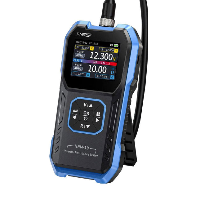
FNIRSI FNIRSI HRM-10 Interne weerstands- en spanningstester voor batterijen
De FNIRSI HRM-10 is een draagbare, zeer nauwkeurige interne weerstands- en spanningstester voor batterijen. Dit apparaat biedt echte vierdraadsmetingen en is ontworpen voor zowel nauwkeurigheid als gebruiksgemak. Het meet automatisch tegelijkertijd de interne weerstands- en spanningswaarden en geeft de resultaten op het HD-kleurenscherm weer. Gebruikers hebben de mogelijkheid om het spannings- en weerstandsbereik handmatig aan te passen aan hun behoeften. Het apparaat bevat ook een sorteermodus die automatisch de goede en slechte batterijen filtert op basis van door de gebruiker ingestelde drempels. Bovendien ondersteunt het de opslag van historische gegevens en is het mogelijk meetgegevens in tabelformaat te exporteren. Kenmerken Hoge meetnauwkeurigheid Tabelgegevens exporteren Meetresultaten automatisch evalueren 8 drempelinstellingen HD-kleurenscherm Opvouwbare standaard 1000 mAh lithiumbatterij Specificaties Spanning Weerstand Meetbereik 0-100 V (DC) 0-200 Ω Nauwkeurigheid ±0,5% ±0,5% Uitrusting Automatisch, 1 V, 10 V, 100 V Automatisch, 20 mΩ, 200 mΩ, 2 Ω, 20 Ω, 200 Ω Instrumenttestsignaalfrequentie 1 Khz (AC) Oplaadbaar USB-C (5 V/1 A) Ingebouwde batterij 1000 mAh lithiumbatterij Gebruikerskalibratie Ja Sorteermodus Ja Geschiedenisrecord Ja Export van opgenomen gegevens Ja Werkomgeving –10°C tot +45°C, relatieve vochtigheid <80% Opslagomgeving –20°C tot +80°C, relatieve vochtigheid <80% Afmetingen 158,7 x 80,5 x 28,4 mm Gewicht 225 g Inbegrepen 1x FNIRSI HRM-10 interne weerstandstester 1x Clip-testlijn 1x USB-C datakabel 1x Manual Downloads Manual Firmware V0.3
€ 49,95
-

Elektor Digital Das CAN-Bus Praxisbuch (PDF)
Projekte mit Arduino Uno und Raspberry Pi In diesem Buch werden Anwendungen von Arduino Uno und Raspberry Pi 4 in praxisnahen Projekten auf Basis von CAN-Bus detailliert beschrieben. Durch den Einsatz von entweder Arduino Uno oder Raspberry Pi in Verbindung mit handelsüblichen CAN-Bus-Schnittstellenmodulen werden die Entwicklung, Fehlersuche und Fehlerbeseitigung sowie die Überprüfung von Projekten auf CAN-Bus-Basis erheblich erleichtert. Dieses Buch richtet sich an jeden, der mehr über den CAN-Bus lernen möchte und mit den Grundlagen der Elektronik vertraut ist. Hilfreich ist auch Erfahrung mit den Programmiersprachen C und Python sowie mit der Programmierung von Arduino Uno unter Verwendung seiner IDE und von Raspberry Pi zu haben. Das Buch ist eine nützliche Informationsquelle und ein Nachschlagewerk für jeden, der Antworten auf eine oder mehrere der folgenden Fragen sucht: Welche Bussysteme stehen für die Automobilindustrie zur Verfügung? Was sind die Grundprinzipien des CAN-Bus? Welche Arten von Frames (oder Datenpaketen) stehen in einem CAN-Bussystem zur Verfügung? Wie können Fehler in einem CAN-Bussystem erkannt werden, und wie zuverlässig ist ein CAN-Bussystem? Welche Arten von CAN-Bus-Controllern gibt es? Welches sind die Funktionsprinzipien des MCP2515 CAN-Bus-Controllers? Wie kann ich ein CAN-Bus-Projekt mit Arduino Uno realisieren? Wie kann ich Arduino oder Raspberry Pi CAN-Bus-Projekte mit 2 und 3 Knoten erstellen? Wie kann ich die Daten auf dem CAN-Bus analysieren? Wie kann ich ein CAN-Bus-Projekt mit Raspberry Pi ausführen?
€ 29,80
Leden: € 26,82
-

Elektor Digital Mastering the I²C Bus (E-book)
Mastering the I²C Bus takes you on an exploratory journey of the I²C Bus and its applications. Besides the Bus protocol, plenty of attention is given to the practical applications and designing a stable system. The most common I²C compatible chip classes are covered in detail. Two experimentation boards are available that allow for rapid prototype development. These boards are completed by a USB to I²C probe and a software framework to control I²C devices from your computer. All samples programs can be downloaded from the 'Attachments/Downloads' section on this page. Projects built on Board 1: USB to I²C Interface, PCA 9534 Protected Input, PCA 9534 Protected Output, PCA 9553 PWM LED Controller, 24xxx EEPROM Module, LM75 Temperature Sensor, PCA8563 Real-time Clock with Battery Backup, LCD and Keyboard Module, Bus Power Supply. Projects built on Board 2: Protected Input, Protected Output, LM75 Temperature Sensor, PCF8574 I/O Board, SAA1064 LED Display, PCA9544 Bus Expander, MCP40D17 Potentiometer, PCF8591 AD/DA, ADC121 A/D Converter, MCP4725 D/A Converter, 24xxx EEPROM Module.
€ 34,95
Leden: € 31,46


