
Zoekresultaten voor "siglent OR sds2354x OR plus OR 4 OR ch OR oscilloscope OR 350 OR mhz"
-

tinySA tinySA Ultra+ ZS407 Spectrumanalyzer
The tinySA Ultra+ ZS-407 is a compact, handheld spectrum analyzer and signal generator. Covering 100 kHz to 7.3 GHz in Ultra mode, it lets you visualize and analyze RF signals from HF right through many modern wireless bands – and can even spot signals up to ~12 GHz thanks to harmonic tracking. The intuitive 4-inch resistive touchscreen and rechargeable battery make it great for fieldwork, while features like a built-in signal generator, switchable bandpass filters, step attenuator, USB-PC control and auto-calibration add serious versatility. Kenmerken Screen size: 4 inch (480 x 320) Spectrum Analyzer for 0.1-900 MHz or, with Ultra mode enabled up to 7.3 GHz, level calibrated up to 7.3 GHz. Can observe signals up to 12 GHz Signal Generator with sine wave output between 0.1-900 MHz or square wave up to 6.3 GHz or RF test signal output up to 7.3 GHz when not used as Spectrum Analyzer. Switchable resolution bandpass filters from 200 Hz to 850 kHz Built-in 20 dB optional LNA Color display showing max 450 points providing gapless covering up to the full frequency range. MicroSD card slot for storing measurements, settings and screen captures. Specificaties (Spectrumanalyzer) Input frequency range from 100 kHz to 900 MHz in normal mode and up to 7.3 GHz with ULTRA mode enabled Input impedance 50 ohm when input attenuation set to 10 dB or more. Selectable manual and automatic input attenuation between 0 dB and 31 dB in 1 dB steps when LNA not active Maximum +/-5V DC input Absolute maximum input level of +6 dBm with 0 dB internal attenuation Absolute maximum short term peak input power of +20 dBm with 30 dB internal attenuation Suggested maximum input power of +0 dBm with internal attenuation in automatic mode For best measurements keep input power below -25 dBm Input Intercept Point of third order modulation products (IIP3) of +15 dBm with 0 dB internal attenuation 1 dB compression point at -1 dBm with 0 dB internal attenuation Power detector resolution of 0.5 dB and linearity versus frequency of ±2 dB below 5.3 GHz, ±5dB between 5.3 GHz and 6 GHz Minimum burst length for correct level measurement at 850 kHz RBW in zero span mode of 50 microseconds Absolute power level accuracy after power level calibration of ±2 dB Built-in optional 20 dB LNA with Noise Figure of 5 dB up to 6 GHz Lowest discernible signal without LNA at 30 MHz using a resolution bandwidth of 30 kHz of -102 dBm Lowest discernible signal with LNA at 30 MHz using a resolution bandwidth of 200 Hz of -145 dBm Frequency accuracy equal to the selected resolution bandwidth Phase noise at 30 MHz of -108 dB/Hz at 100 kHz offset and -115 dB/Hz at 1MHz offset Spur free dynamic range when using a 30 kHz resolution bandwidth of 70 dB Resolution filters with a width of 0.2, 1, 3, 10, 30, 100, 300, 600 and 850 kHz On screen resolution of 51, 101, 145, 290 or 450 measurement points. Scanning speed of over 1000 points/second using largest resolution filters. Automatic optimization of actual scanning points to ensure coverage of the whole scan range regardless of the chosen resolution bandwidth Spur suppression option for assessing if certain signals are internally generated or actually present in the input signal Headphone output for listening to the demodulated audio (AM only). Stereo connector with or without microphone, high impedance is louder, short protected Specificaties (Signaalgenerator) Sine wave output with harmonics below -40 dB of fundamental from 100 kHz to 900 MHz Output level selectable in 1 dB steps between -115 dBm and -19 dBm Above 800 MHz choice of two output modes: Cleanest signal mode: square wave, up to 6 GHz with coarse frequency steps and less accurate output level Highest accuracy mode: reduced harmonics with possibly strong spurs up to 7.3 GHz with frequency resolution equal to below 800 MHz and fine output level steps Level accuracy ±2 dB up to 800 MHz between -72 dBm and -19 dBm, less accuracy below -72 dBm, even less accuracy below -110 dBm Output frequency resolution 57.2 Hz Optional AM or FM modulation frequencies between 50 Hz and 5 kHz (AM) or 1 kHz (FM) or sweep over selectable frequency span AM modulation depth between 10% and 100% FM deviation between 1 kHz and 300 kHz Optional output level sweep over maximum the entire output level range Inbegrepen 1x tinySA Ultra+ ZS407 Spectrum Analyzer 2x SMA connection cables 1x Barrel connector 1x Antenna with SMA connector 1x USB-C cable 1x microSD card (32 GB) Downloads Wiki
€ 196,02
-

OWON OWON XDG2035 2-ch Arbitrary Waveform Generator (35 Mhz)
The 2-channel OWON XDG2035 is a function/waveform generator that can generate signals with a maximum frequency of 35 Hz. The generator has a resolution of 1 µHz and a sample rate of 500 MSa/s.The OWON XDG2035 is capable of generating 6 standard waveforms and 150 arbitrary waveforms. With the included software you can write advanced functions up to 10 million points. Waveforms can be saved to the function generator's internal memory using a PC via USB or LAN.The OWON XDG2035 also supports SCPI commands and LabView. The function generator has an integrated high-quality frequency counter, which can operate from 100 to 200 MHz.Features Max. 35 MHz frequency output 500 MSa/s Sample rate, Vertical resolution 1μHz 14 bits Vertical Resolution, 10 Marb waveform length Comprehensive waveform output: 6 basic waveforms,and 150 built-in arbitrary waveforms Comprehensive modulation functions: AM, FM, PM, FSK, 3FSK, 4FSK, PSK, OSK, ASK, BPSK, PWM, Sweep, and Burst High-accuracy frequency counter integrated, supported range 100-200 MHz SCPI and LabVIEW supported 7 inch multi-touch screen (800 x 480 pixels) Specifications Channel 2 Frequency Output 35 MHz Sample Rate 500 MSa/s Vertical Resolution 14 bits Waveform Standard Waveform sine, square, pulse, ramp, noise, and harmonic Arbitrary Waveform exponential rise, exponential fall, sin(x)/x, step wave, and others, total 150 built-in waveforms, and user-defined arbitrary waveform Frequency (resolution 1 μHz) Sine 1 μHz-100 MHz Square 1 μHz ~ 30 MHz Pulse 1 μHz ~ 25 MHz Ramp 1 μHz ~ 3 MHz Noise (-3 dB, typical) 100 MHz Arbitrary Waveform 1 μHz ~ 15 MHz Harmonic 1 μHz ~ 50 MHz Accuracy ±2ppm, 25°C ±5°C Waveform Length 2 points - 10M points Amplitude Into 50Ω load 1mVpp ~ 10Vpp (≤25 MHz); 1mVpp ~ 5Vpp (≤60 MHz); 1mVpp ~ 2.5Vpp (≤100 MHz) Modulation Type AM, DSB-AM, FM, PM, ASK, FSK, PSK, BPSK, QPSK, 3FSK, 4FSK, OSK, PWM, SUM Frequency Counter Function Frequency, period, +width, -width, +duty, and -duty Frequency Range 100 ~ 200 MHz Frequency Resolution 7 digits Input/Output Input mode frequency counter, external modulation input, external trigger input, internal clock output, external reference clock input/output Communication Interface USB Host, USB Device, LAN, RS232 (optional) Mechanical specifications Dimensions 340 x 177 x 90 mm Weight 2.3 kg Included 1x OWON XDG2035 1x Power Cord 1x CD-ROM 1x Quick start guide 1x USB Cable 1x BNC-BNC Cable DownloadsQuick Guide
€ 339,00
-

Rigol Rigol RSA3015E-TG Real-time Spectrumanalyzer (9 kHz – 1.5 GHz)
Highlights Frequency: 1.5 GHz DANL: -161 dBm Phase Noise: -102 dBc/Hz RBW: 1 Hz Specificaties Ultra-Real technology Frequency: up to 1.5 GHz Displayed average noise level (DANL): <-161 dBm (typical) Phase noise: <-102 dBc/Hz (typical) Level measurement uncertainty: <1.0 dB 1.5 GHz tracking generator Min. RBW 1 Hz Up to 10 MHz real-time analysis bandwidth Multiple measurement modes Various advanced measurement functions EMI measurement application (option) Multiple trigger modes and trigger masks Density, spectrogram, and other display modes PC software options 10.1'' capacitive multi-touch screen; supporting touch gestures USB, LAN, HDMI and other communication and display interfaces Inbegrepen 1x Rigol RSA3015E-TG Spectrum Analyzer 1x Power cord 1x USB cable
€ 2.176,79
-

Elektor Digital Elektor 05-06/2024 (PDF)
Diese Ausgabe steht allen GOLD- und GREEN-Mitgliedern auf der ElektorMagazine-Website zum Download bereit! Sie sind noch kein Mitglied? Hier klicken! STM32 Wireless Innovation Design Contest – Die Gewinner stehen fest In-Circuit LC-MeterEine Prototyp-Studie Das modulare DC-Leistungsmessgerät AmpVoltTeil 1: Platine zur Messung von Strömen bis 5 A und Spannungen bis 50 V embedded world 2024 Reparatur von elektronischen GerätenWerkzeuge, Techniken und Tipps Aller Anfang ...muss nicht schwer sein: Wir setzen die Verstärkertheorie fort! Ein einfacher DDS-SignalgeneratorDirekte Digitale Synthese in ihrer reinsten Form Sparkplug im ÜberblickEine Spezifikation für MQTT-Daten Bemerkenswerte BauteileZeile für Zeile: CRTCs Radargesteuerte BeleuchtungAutomatisches Treppenhauslicht mit Anwesenheitsdetektion Digitale Wasserwaage und aktive Stroboskop-Scheibe für PlattenspielerFeinabstimmung Ihres Plattenspielers mit nur einem Gerät Open Source und seine Bedeutung für die Elektronikindustrie (2) M12-Rundsteckverbinder mit A-KodierungErste Wahl für industrielle Anwendungen Arduino-MesslaborEin 8-in-1-Test- und Messgerät für das heimische Elektroniklabor Soundkarte als Betrag/Phase-Impedanz-AnalysatorFür Frequenzen von 100 Hz bis 90 kHz pH-Wert-Messung mit dem Arduino UNO R4Überprüfen Sie die Qualität Ihres Wassers Aus dem Leben gegriffenStartrampe für Pangpong-Popöchen Digitales Speicheroszilloskop FNIRSI 1014DGute Leistung für knappe Budgets 2024: Eine Odyssee in die KIWie man die Objekterkennung zum Laufen bringt 10-MHz-ReferenzgeneratorHochgenau, mit Verteiler und galvanischer Trennung Projekt-Update #2: Energiemessgerät mit ESP32Einige Weiterentwicklungen Projekt 2.0Korrekturen, Updates und Leserbriefe Ein Interview mit Eben Upton, Geschäftsführer von Raspberry PiDer Raspberry Pi 5 und darüber hinaus
€ 11,90
-

Elektor Digital Elektor May/June 2026 (PDF) EN
Elektor GREEN and GOLD members can download their digital edition here. Not a member yet? Click here. PbMonitor v2.0 UpdateBattery Monitoring with Improved Analog Design Audio Latency MeasurementA Standalone Tool for Evaluating Errors and Latency in Audio Transmission Square Wave vs. Bode PlotChecking the Performances of an Audio Device embedded world 2026 Clever Coding with AIAI in Software Development for Electronics Engineers QA403 Audio AnalyzerAffordable Precision for Audio Professionals and Hobbyists EasyGimbalAutonomous Camera Tracking with AI, Stepper and Servo Motors Sigfox Breakout Board (2)Sending Messages Circuit ProtectionControlling Overvoltages with TVS Diodes Emerging Battery Testing ApproachesA New Era of Diagnostics AudiotronicsA First Preamplifier CANopenTermAn Open-Source Tool That Brings CAN to Makers and Engineers Alike Stabilization of Operational AmplifiersAvoiding Feedback Instability Err-lectronicsCorrections, Updates, and Readers’ Letters Signal ConditioningTips and Tricks to Fit Voltage Ranges TDR Attachment for OscilloscopesLength, Short Circuit, Mismatch: Measure Cables Using Reflections! From Life's ExperienceLED It Be Speaker Oscillator and Resonance TesterA Fully Experimental Project for Your Speakers Elektor Community Perspectives on Test and Measurement ESP32 Audio Transceiver Board (Part 5)Audio Processing and Remote Control 2026: An AI OdysseyAI Has a Context Problem Battery Storage for Balcony Power PlantsSmall Batteries, Big Impact
€ 9,50
-

Rigol Rigol DP832 3-kanaals DC-Voeding (0-30 V, 0-3 A, 195 W)
Specificaties Channels: 3 Total Power: 195 Watts Max. Voltage: 30 Volts Max. Current: 3 Amps Low ripple and noise: <350 ?Vrms/2 mVpp Excellent linear regulation rate and load regulation rate Fast transient response time: <50 ?s Some channels are isolated Standard OVP/OCP/OTP protection functions Standard timing output Built-in V,A,W measurements and waveform display Independent control for each channel 3.5 inch TFT display Inbegrepen 1x Rigol DP832 DC Power Supply 1x Power cord 1x USB cable
€ 427,21
-

Elektor Digital The Arduino-Inside Measurement Lab (E-book)
An 8-in-1 test & measurement instrument for the electronics workbench A well-equipped electronics lab is crammed with power supplies, measuring devices, test equipment and signal generators. Wouldn‘t it be better to have one compact device for almost all tasks? Based on the Arduino, a PC interface is to be developed that’s as versatile as possible for measurement and control. It simply hangs on a USB cable and – depending on the software – forms the measuring head of a digital voltmeter or PC oscilloscope, a signal generator, an adjustable voltage source, a frequency counter, an ohmmeter, a capacitance meter, a characteristic curve recorder, and much more. The circuits and methods collected here are not only relevant for exactly these tasks in the "MSR" electronics lab, but many details can also be used within completely different contexts.
€ 29,95
Leden: € 26,96
-

Elektor Digital PIC Cookbook for Virtual Instrumentation (E-book)
The software simulation of gauges, control-knobs, meters and indicators which behave just like real hardware components on a PC’s screen is known as virtual instrumentation. In this book, the Delphi program is used to create these mimics and PIC based external sensors are connected via a USB/RS232 converter communication link to a PC. Detailed case studies in this Book include a virtual compass displayed on the PC’s screen, a virtual digital storage oscilloscope, virtual -50 to +125 degree C thermometer, and FFT sound analyser, a joystick mouse and many examples detailing virtual instrumentation Delphi components. Arizona’s embedded microcontrollers – the PIC's are used in the projects and include PIC16F84A, PIC16C71, DSPIC30F6012A, PIC16F877, PIC12F629 and the PIC16F887. Much use is made of Microchip’s 44 pin development board (a virtual instrument ‘engine)’, equipped with a PIC16F887 with an onboard potentiometer in conjunction with the PIC’s ADC to simulate the generation of a variable voltage from a sensor/transducer, a UART to enable PC RS232 communications and a bank of 8 LED's to monitor received data is also equipped with an ISP connector to which the ‘PICKIT 2’ programmer may easily be connected. Full source code examples are provided both for several different PIC’s, both in assembler and C, together with the Pascal code for the Delphi programs which use different 3rd party Delphi virtual components.
€ 19,95
Leden: € 17,96
-

Miniware Miniware MDP-P906 Digital Power Supply (300 W)
De MDP-P906 heeft een ingebouwde ventilator en een maximaal uitgangsvermogen van 300 W, wat toereikend is voor een breed scala aan testbehoeften en toepassingen. Via 2,4 GHz draadloze communicatie kan hij worden aangesloten op de MDP-M01 Smart Digital Monitor module om daarmee een flexibele combinatie van meerdere kanalen van 300 W per kanaal te kunnen realiseren. De MDP-P906 heeft een basis, stabiliteit en betrouwbaarheid die te vergelijken is met een professionele voeding. Hij kan puur stroom leveren én krachtige functies hieraan toevoegen, zoals programmeerbare uitgang, getimede uitgang, getimede regeling, automatische compensatie, boost modus, enz. Dit maakt hem tot een kosteneffectieve, slimme en op maat programmeerbare lineaire DC-voeding. De MDP-P906 heeft een zorgvuldig CNC-gefreesde aluminium behuizing, met verfijnde afwerking, eigentijds, bescheiden en prachtig uiterlijk. Hij wijkt hiermee volledig af van het standaard uiterlijk van een traditionele desktop voeding. Door een stackable modulair ontwerp en de draadloze communicatie kan de MDP-P906 onafhankelijk of onderling gekoppeld worden gebruikt, zowel in de normale werkruimte als bij onderhoud op locatie. De MDP-P906 is een perfecte oplossing voor elektrotechnici, met name servicemonteurs, om bij verschillende situaties en toepassingen de stroom te leveren. Ingebouwde stille ventilator, instant cooling, voor een stabiele en efficiënte output! Slimme lineaire compensatie, constante spanning & constante stroom Positieve en negatieve output, series boost, parallelle stroomverdeling Toepassingen Universele tests en onderwijsexperimenten in R&D laboratoria Onderhoud van digitale producten Eigendomsverificatie en foutdiagnose van apparaten en circuits Noodstroomvoorziening voor modelvliegtuigen en voertuigen Voedingen testen van RF en microgolfcircuits of -modules Kwaliteitscontrole en kwaliteitsinspectie Zuivere voeding voor zeer nauwkeurige digitaal-analoge hybride circuits en Hi-Fi audioapparaten Specificaties Input DC 4.2-30 V / 14 A (Max)QC 3.0/PD2.0, 20 V / 5 A (Max) Uitgang 0-30 V / 0-10 A, 300 W (Max) Conversie efficiëntie 95% Output resolutie 10 mV / 2 mA, tot 1 mV / 1 mA via Display Control module Output nauwkeurigheid 0,03%+5 mV0,05%+2 mV Adjustment rate Load adjustment rate <±0,01%Power adjustment rate <±0,01% Ripple en noise <250 uVrms, 3 mVpp; 2 mArms Transient response <4 uS Beveiligingen Te hoge voedingsspanning, onderspanning, omgekeerd aansluiten, te hoge uitgangsstroom, retourstroom en oververhitting Overig Automatisch afsluiten en naar micro-power modeOndersteuning van USB firmware upgrade Afmetingen 112 x 66 x 20 mm Gewicht 181 g Inbegrepen 1x MDP-P906 digitale voeding 2x uitgangskabel 1x gebruikershandleiding Downloads User Manual v1.1 Firmware v1.32
€ 171,95
-
QuantAsylum QuantAsylum QA403 24-bit Audio Analyzer
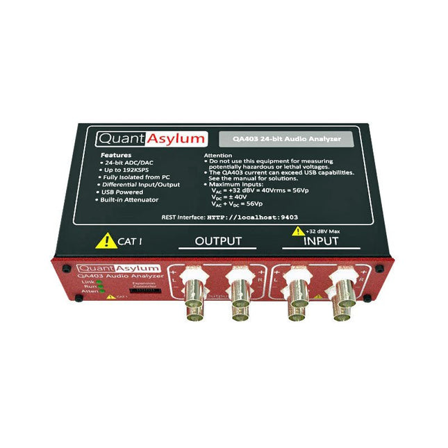
De QA403 is de vierde generatie audio analyzer van QuantAsylum. Deze QA403 verhoogt de functionaliteit van de QA402 met verbeterde ruis- en vervormingsprestaties, en ook een vlakkere respons aan de randen van de band. Het compacte formaat van de QA403 zorgt ervoor dat u hem vrijwel overal mee naartoe kunt nemen. Kenmerken 24-bits ADC/DAC Tot 192 kS/s Volledig geïsoleerd van de PC Differentiële input/output USB gevoed Ingebouwde demping Snel opstarten en geen stuurprogramma De QA403 is een USB-apparaat zonder stuurprogramma's, wat betekent dat hij meteen operationeel is zodra u hem aansluit. De software is gratis, en u kunt snel en gemakkelijk de hardware van de ene machine naar de andere verplaatsen. Dus als u naar een vestiging moet om een probleem op te lossen, of de QA403 mee naar huis dient te nemen op een thuiswerkdag, dan kunt u dit zonder veel gedoe doen. No-Cal ontwerp De QA403 wordt geleverd met een fabriekskalibratie in het flashgeheugen, waardoor consistente prestaties bij gebruik van meerdere analyzers kan worden gegarandeerd. Op uw productielijn kunt u een andere QA403 installeren en erop vertrouwen dat wat u op de ene analyzer leest overeenkomt met de andere. Er hoeft dus niet geregeld herkalibratie plaats te vinden. Metingen Het uitvoeren van basismetingen kan snel en eenvoudig. In een paar klikken krijgt u inzicht in de frequentierespons, de THD (+ N), de versterking, de SNR, en andere gegevens van uw geteste apparaat. Dynamisch bereik De QA403 biedt 8 gradaties aan versterking op de ingang (0 tot +42 dBV in 6 stappen) en 4 stappen versterking op de uitgang (-12 tot +18 dBV in stappen van 10 dB). Dit zorgt voor consistente prestaties over zeer brede in- en uitgangsniveaus. De maximale AC ingangsspanning op de QA403 is +32 dBV = 40 Vrms. De maximale DC is ±40 V en de maximale ACPEAK + DC = ±56 V. Eenvoudig te programmeren De QA403 ondersteunt een REST-interface, waardoor het eenvoudig is om metingen te automatiseren in vrijwel elke taal. Van Python tot C++ tot Visual Basic: als u weet hoe u een webpagina in uw favoriete taal moet laden dan kunt u al de QA403 op afstand bedienen. Metingen zijn snel en responsief, doorgaans met het verwerken van tientallen opdrachten per seconde. Geïsoleerd, en gevoed via USB De QA403 werkt geïsoleerd van de pc, wat betekent dat u echt uw te testen apparaat meet, en niet met een fantoom aardlus te doen heeft. De QA403 wordt gevoed via USB, zoals bijna alle QuantAsylum instrumenten. Indien u op afstand moet configureren, neem dan een hub met voeding mee in uw tas en uw hele testopstelling kan dan functioneren met een minimum aan kabels. Vaarwel geluidskaart, hallo QA403 Moe van het proberen om een geluidskaart aan de praat te krijgen? Nachtmerries van het kalibreren? Gemis van de juiste versterking? Of te weinig aansturing? Bent u het zat om met vaste ingangsranges om te gaan? Of bang dat u zaken kapot maakt met te veel DC of AC? Moe van de aardlussen? Dáarom heeft QuantAsylum de QA403 ontworpen. Specificaties Case Materiaal Aluminium met poedercoating (2 mm dik voorpaneel, 1.6 mm dikke boven/onderkant) Afmetingen 177 x 44 x 97 mm (B x H x D) Gewicht 435 g Downloads Datasheet Manual GitHub
-

Great Scott Gadgets Great Scott Gadgets HackRF Pro SDR (100 kHz – 6 GHz) + GRATIS e-book
ACTIE: Bestel de HackRF Pro nu en ontvang het nieuwe e-book "SDR with HackRF One & HackRF Pro" ter waarde van € 20 gratis! HackRF Pro is de nieuwste Software Defined Radio (SDR) van Great Scott Gadgets en de krachtige opvolger van de legendarische HackRF One. Met een frequentiebereik van 100 kHz tot 6 GHz bestrijkt het een enorm spectrum voor het verzenden en ontvangen van radiosignalen. Ontworpen als een open-source hardwareplatform, is de HackRF Pro de ideale tool voor het analyseren en ontwikkelen van moderne draadloze technologieën. Het kan flexibel worden gebruikt als USB-randapparaat of worden geprogrammeerd voor zelfstandig (standalone) gebruik. Specificaties Frequentie: 100 kHz tot 6 GHz Instelbaar van 0 Hz tot 7,1 GHz Half-duplex transceiver Tot 20 miljoen samples per seconde 8-bits kwadratuur-samples (8-bits I en 8-bits Q) Compatibel met GNU Radio, SDR# en meer Softwarematig configureerbare RX- en TX-versterking en basisbandfilter Softwarematig geregelde RF-poortvoeding (50 mA bij 3,3 V) SMA RF-connector SMA-klokingang en -uitgang voor synchronisatie en triggering Handige knoppen voor programmering Interne pinheaders voor uitbreiding High-Speed USB 2.0 met USB-C connector Voeding via USB Open source hardware In vergelijking met zijn voorganger, biedt HackRF Pro een aantal nieuwe functies, waaronder: Breder werkfrequentiebereik Verbeterde RF-prestaties met een vlakkere frequentierespons USB-C-connector Ingebouwde TCXO-kristaloscillator voor superieure timingstabiliteit Logica-upgrade van een CPLD naar een energiezuinige FPGA Eliminatie van de DC-piek Uitgebreide precisie-modus met 16-bits samples voor lage samplefrequenties (typische ENOB: 9-11) Halfprecisie-modus met 4-bits samples tot 40 Msps Meer RAM en flashgeheugen voor aangepaste firmware Afscherming rond het radiogedeelte Trigger-ingang en -uitgang toegankelijk via klokconnectoren Uitsparing in de printplaat biedt ruimte voor toekomstige uitbreidingen add-ons Verbeterd energiebeheer Verbeterde bescherming van de RF-poort Mogelijkheid om de zendmodus hardwarematig uit te schakelen Volledige compatibiliteit: Dankzij de beproefde architectuur kan bestaande software voor de HackRF One ook direct worden gebruikt met de HackRF Pro. De HackRF Pro biedt naadloze achterwaartse compatibiliteit en tegelijkertijd aanzienlijk verbeterde prestaties. Let op: Een antenne is niet inbegrepen. Wij raden de ANT500 aan voor een optimale start. Inbegrepen HackRF Pro SDR met kunststofbehuizing Nieuw e-book: SDR with HackRF One & HackRF Pro (normale prijs: € 20) Downloads Documentation GitHub
-
Great Scott Gadgets Great Scott Gadgets Opera Cake (Antenneschakelaar voor HackRF SDR)
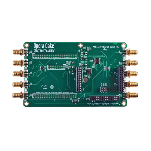
Opera Cake is een antenne-schakelboard voor HackRF One/Pro dat wordt geconfigureerd met command-line software, zowel handmatig of met een automatische poortschakeling op basis van frequentie of tijd. Het heeft twee primaire poorten, elk verbonden met een van de acht secundaire poorten, en is geoptimaliseerd voor gebruik als een paar 1x4 switches of als een enkele 1x8 switch. Wanneer HackRF One/Pro wordt gebruikt om te zenden, kan Opera Cake automatisch zijn uitgang naar de juiste zendantennes leiden, evenals eventuele externe filters, versterkers, enz. Er zijn geen wijzigingen nodig in de bestaande SDR software, maar volledige controle vanaf de host is mogelijk. Opera Cake verbetert ook het gebruik van de HackRF One/Pro als spectrum analyzer over het gehele frequentiebereik van 1 MHz tot 4 GHz. Het schakelen van antennes werkt met de bestaande hackrf_sweep functie, die het hele afstembereik in minder dan een seconde kan doorlopen. Automatisch schakelen halverwege de sweep maakt het gebruik van meerdere antennes mogelijk bij het sweepen van een groot frequentiebereik. Downloads Documentation GitHub


