
Zoekresultaten voor "siglent OR oscilloscope OR sds1102x"
-

Siglent Siglent SPD3303X 3-kanaals DC-voeding (220 W)
Deze SPD3000X Series Linear Programmable DC Power Supply heeft een 4,3-inch TFT LCD-scherm, is te programmeren en heeft Real Time Wave Display, wat gebruikers een geheel nieuwe ervaring geeft. Hij heeft drie aparte uitgangen: twee regelbare uitgangen, en een instelbare uitgang van 2,5V, 3,3V en 5V. Hij heeft ook beveiligingsfuncties tegen kortsluiting en overbelasting, en kan goed worden ingezet bij productie en ontwikkeling. Kenmerken 3 onafhankelijk instelbare en apart uitgevoerde uitgangen: 32V/3,2A×2, 2,5V/3,3V/5V/3,2A×1, totaal 220W. 5 digit spannings- en 4 digit stroomweergave, minimale resolutie: 1mV/1mA. Ondersteunt panel timing uitgangsfuncties. 4,3-inch true color TFT LCD-scherm, 480 x 272 pixels. 3 soorten uitgangsmodi: onafhankelijk, serie, parallel. 100V/120V/220V/230V compatibel ontwerp, om te kunnen worden aangesloten op verschillende elektriciteitsnetten. Intelligente temperatuur-gestuurde ventilator, waardoor het geluid effectief verminderd wordt. Duidelijke grafische interface, met golfvorm weergave functie. Intern 5 groepen van systeemparameters op te slaan / op te vragen, ondersteuning voor uitbreiding van de data opslagruimte. Met PC-software: Easypower, ondersteunt SCPI, LabVIEW driver. Uitgangen met hoge resolutie en hoge precisie De hoge resolutie van 1mV/1mA zorgt voor een uitstekende instel- en afleesnauwkeurigheid. Dit zorgt voor een zeer precieze uitvoer, zelfs bij zeer kleine veranderingen in spanning of stroom. Dit zou onmogelijk zijn bij een voeding met een lage resolutie. Serie/parallel/onafhankelijke uitgang De serie- en parallelfunctie maakt het mogelijk om twee kanalen te combineren in één uitgang met meer uitgangsvermogen, waardoor het aantal toepassingen kan worden uitgebreid. Elk van de 3 kanalen kan onafhankelijk worden in- of uitgeschakeld, of ze kunnen allemaal tegelijk worden in- of uitgeschakeld. Paneel geeft de output timing weer Via het bedieningspaneel kunnen 5 groepen timing-instellingen en de output controle worden weergegeven, wat gebruikers een eenvoudige power-programmeer functie geeft. Er kan ook een verbinding worden gemaakt met Siglent's EasyPower PC-software, die een volledig scala aan communicatie- en besturingsopties biedt. Instelparameters opslaan/opvragen De programmeerbare voeding van de SPD3000X-serie kan 5 groepen instellingsparameters in de interne opslag opslaan of hieruit opvragen, en ondersteunt tevens uitbreiding van externe opslag. U kunt daarmee eenvoudig de benodigde instellingen opvragen.
€ 600,50
-
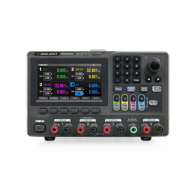
Siglent Siglent SPD4323X 4-kanaals Voeding (240 W)
The Siglent SPD4323X is a 4-channel DC Linear Programmable Power Supply equipped with a 4.3-inch TFT-LCD display, friendly human-machine interface, and excellent performance indicators. Real-time waveform display provides engineers with an informative user interface. SPD4323X offers a total output power of 240 W with a resolution of 1 mV/1 mA. The maximum voltage and current for each channel are as follows: CH1: 6 V/3.2 A CH2: 32 V/3.2 A CH3: 32 V/3.2 A CH4: 6 V/3.2 A Kenmerken Rated output power: 240 W Rated voltage: 32 V, 12 V, 30 V Up to four high-precision power supplies with independent controllable outputs, supporting CH2 and CH3 series and parallel connections Clear graphical interface with waveform and timer display modes 5-digit voltage and current display with minimum resolution of 1 mV, 1 mA Fast output response time: <50us The high current channel support remote voltage compensation sense function. The maximum compensation voltage is 0.6 V Overvoltage protection and overcurrent protection or safe and accurate operation Equipped with a 4.3-inch TFT-LCD display (480 x 272 resolution) USB and LAN standard communication USB-GPIB module is optional Excellent channel density with up to 4 channels in a 3U half rack package Internal data storage for setups and parameters Embedded Web Server with instrument communication that doesn’t require software installation Fully SCPI programming command set support as well as a LabView driver for remote control and system automation Specificaties SPD4323X SPD4121X SPD4306X Channel Output CH1: Voltage 0 to 6 V Current 0 to 3.2 ACH2: Voltage 0 to 32 V Current 0 to 3.2 ACH3: Voltage 0 to 32 V Current 0 to 3.2 ACH4: Voltage 0 to 6 V Current 0 to 3.2 A CH1: Voltage 0 to 15 V Current 0 to 1.5 ACH2: Voltage 0 to 12 V Current 0 to 10 ACH3: Voltage 0 to 12 V Current 0 to 10 ACH4: Voltage 0 to 15 V Current 0 to 1.5 A CH1: Voltage 0 to 15 V Current 0 to 1.5 ACH2: Voltage 0 to 30 V Current 0 to 6 ACH3: Voltage 0 to 30 V Current 0 to 6 ACH4: Voltage 0 to 15 V Current 0 to 1 A Resolution 1 mV, 1 mA 1 mV, 1 mA 1 mV, 1 mA Setting Accuracy Voltage: ±(0.03% of reading+10) mV, Current: ±(0.3% of reading+10) mA Voltage: ±(0.03% of reading+10) mV, Current: ±(0.3% of reading+10) mA Voltage: ±(0.03% of reading+10) mV, Current: ±(0.3% of reading+10) mA Readback Accuracy Voltage: ±(0.03% of reading+10) mV, Current: ±(0.3% of reading+10) mA Voltage: ±(0.03% of reading+10) mV, Current: ±(0.3% of reading+10) mA Voltage: ±(0.03% of reading+10) mV, Current: ±(0.3% of reading+10) mA Display 4.3" TFT-LCD 5-digit voltage and current display 4.3" TFT-LCD 5-digit voltage and current display 4.3" TFT-LCD 5-digit voltage and current display Output power 240 W 285 W 400 W Inbegrepen 1x Siglent SPD4323X Power Supply 1x Power cord (EU) 1x Output test cord (3 A) 1x USB cable 1x Quick start guide Downloads Datasheet Manual Quick start
€ 762,30
-
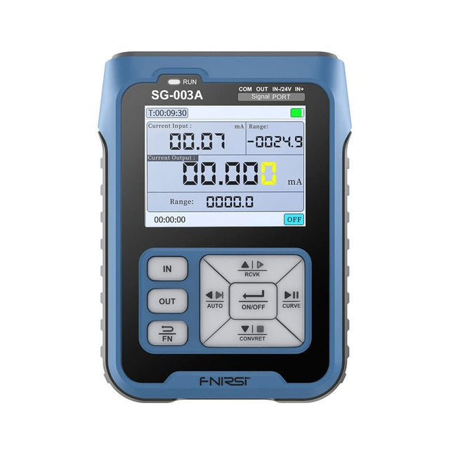
FNIRSI FNIRSI SG-003A Signaalgenerator
De FNIRSI SG-003A multifunctionele signaalgenerator, ook bekend als procesmeter/kalibrator, is een zeer nauwkeurige spanning-/stroomgenerator en -meter. De SG-003A levert zeer nauwkeurige referentiespanningen of -stromen voor het testen en kalibreren van andere meetinstrumenten, zoals multimeters en oscilloscopen. Naast spanningen en stromen genereert de SG-003A ook rechthoekige puls signalen met nauwkeurig programmeerbare frequenties en inschakelduur. De convertor modus verandert de SG-003A in een nauwkeurige spanning gestuurde stroombron, of stroom gestuurde spanningsbron, en zelfs in een spanning- of stroom gestuurde frequentiegenerator. De SG-003A is een zeer handig hulpmiddel voor het controleren van de nauwkeurigheid en precisie van uw multimeter, en voor het testen van bijvoorbeeld LED's. Kenmerken Nauwkeurigheid (spanning/stroom) 0,1% ± 0,005 Resolutie (huidig) 0,01 mA Frequentie 0-10 kHz Resolutie 5 cijfers Uitgangsspanning 24 V Scherm 2,4" TFT LCD-scherm (320 x 240) Afmetingen 92 x 72 x 30 mm Gewicht 165 g Specificaties Signaal Bereik Precisie Resolutie Max belasting Externe voeding Actieve stroomuitgang 0~24 mA ±(0,1% + 0,005) 0,01 mA 750 Ω Passieve stroomuitgang (XMT) 0~24 mA ±(0,1% + 0,005) 0,01 mA 0~30 V Uitgangsspanning 0~24 V ±(0,1% + 0,005) 0,01 V 24 V loop 0~24 mA ±(0,1% + 0,005) 0,01 mA Frequentie uitgang 0~9999 Hz ±2% 5 cijfers Stroom ingang 0~24 mA ±(0,1% + 0,005) 0,01 mA Spanning ingang 0~3 0V ±(0,1% + 0,005) 0,01 V Inbegrepen 1x FNIRSI SG-003A signaalgenerator 4x Testclips 1x USB oplader 1x USB-C kabel 1x Handleiding Downloads Manual Firmware V4.3
€ 69,95
-
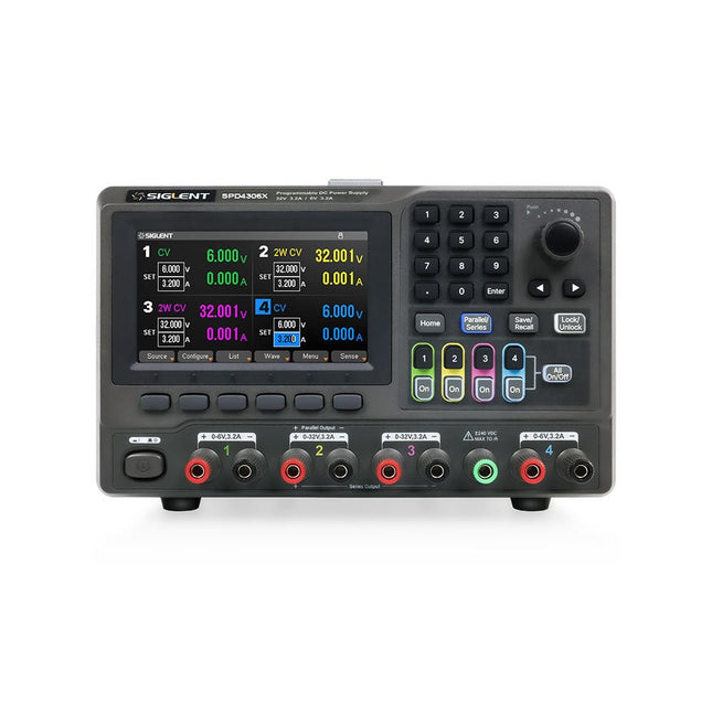
Siglent Siglent SPD4306X 4-kanaals Voeding (400 W)
The Siglent SPD4306X is a 4-channel DC Linear Programmable Power Supply equipped with a 4.3-inch TFT-LCD display, friendly human-machine interface, and excellent performance indicators. Real-time waveform display provides engineers with an informative user interface. SPD4306X offers a total output power of 400 W with a resolution of 1 mV/1 mA. The maximum voltage and current for each channel are as follows: CH1: 15 V/1.5 A CH2: 30 V/6 A CH3: 30 V/6 A CH4: 15 V/1 A Kenmerken Rated output power: 400 W Rated voltage: 32 V, 12 V, 30 V Up to four high-precision power supplies with independent controllable outputs, supporting CH2 and CH3 series and parallel connections Clear graphical interface with waveform and timer display modes 5-digit voltage and current display with minimum resolution of 1 mV, 1 mA Fast output response time: <50us The high current channel support remote voltage compensation sense function. The maximum compensation voltage is 0.6 V Overvoltage protection and overcurrent protection or safe and accurate operation Equipped with a 4.3-inch TFT-LCD display (480 x 272 resolution) USB and LAN standard communication USB-GPIB module is optional Excellent channel density with up to 4 channels in a 3U half rack package Internal data storage for setups and parameters Embedded Web Server with instrument communication that doesn’t require software installation Fully SCPI programming command set support as well as a LabView driver for remote control and system automation Specificaties SPD4323X SPD4121X SPD4306X Channel Output CH1: Voltage 0 to 6 V Current 0 to 3.2 ACH2: Voltage 0 to 32 V Current 0 to 3.2 ACH3: Voltage 0 to 32 V Current 0 to 3.2 ACH4: Voltage 0 to 6 V Current 0 to 3.2 A CH1: Voltage 0 to 15 V Current 0 to 1.5 ACH2: Voltage 0 to 12 V Current 0 to 10 ACH3: Voltage 0 to 12 V Current 0 to 10 ACH4: Voltage 0 to 15 V Current 0 to 1.5 A CH1: Voltage 0 to 15 V Current 0 to 1.5 ACH2: Voltage 0 to 30 V Current 0 to 6 ACH3: Voltage 0 to 30 V Current 0 to 6 ACH4: Voltage 0 to 15 V Current 0 to 1 A Resolution 1 mV, 1 mA 1 mV, 1 mA 1 mV, 1 mA Setting Accuracy Voltage: ±(0.03% of reading+10) mV, Current: ±(0.3% of reading+10) mA Voltage: ±(0.03% of reading+10) mV, Current: ±(0.3% of reading+10) mA Voltage: ±(0.03% of reading+10) mV, Current: ±(0.3% of reading+10) mA Readback Accuracy Voltage: ±(0.03% of reading+10) mV, Current: ±(0.3% of reading+10) mA Voltage: ±(0.03% of reading+10) mV, Current: ±(0.3% of reading+10) mA Voltage: ±(0.03% of reading+10) mV, Current: ±(0.3% of reading+10) mA Display 4.3" TFT-LCD 5-digit voltage and current display 4.3" TFT-LCD 5-digit voltage and current display 4.3" TFT-LCD 5-digit voltage and current display Output power 240 W 285 W 400 W Inbegrepen 1x Siglent SPD4306X Power Supply 1x Power cord (EU) 1x Output test cord (3 A) 1x USB cable 1x Quick start guide Downloads Datasheet Manual Quick start
€ 1.101,10
-

Elektor Digital Les oscilloscopes anciens & modernes pour les débutants (E-book)
Ce qui se passe en électronique est par définition invisible à l'oeil nu. L'instrument qui permet précisément de rendre visibles les signaux électriques, celui par le truchement duquel les effets de l'électronique se manifestent à nous, c'est l'oscilloscope. Hélas, quand on commence à faire de l'électronique, c'est souvent sans oscilloscope. Et l'on en est réduit à tâtonner, aussi bien physiquement que mentalement. Le jour où l'on goûte à la visualisation des signaux sur un écran, c'est une révélation. Plus personne ne souhaite se priver de cet enchantement. Pas de retour en arrière. En électronique, si l'on veut progresser dans le plaisir et dans la compréhension, il faut un oscillo. Commence alors une période d'interrogation : comment choisir ? Et à peine cette question-là aura-t-elle trouvé sa réponse, il en viendra une ribambelle d'autres que l'on peut résumer en une seule : comment se servir de l'oscilloscope de telle sorte que ce qu'il affiche corresponde bien à la réalité des signaux ? Dans ce livre, Rémy Mallard, répond clairement à ces questions. Il donne aussi de nombreuses informations pour aider son lecteur à élucider lui-même de nouveaux mystères qui ne manqueront pas de surgir. Ceux qui le connaissent déjà comme l'auteur d'un livre sur l'électronique dont le titre est un programme à lui tout seul : L'électronique pour les débutants qui sèchent les cours mais soudent sans se brûler les doigts, ainsi que d'un livre d'initiation à la programmation des microcontrôleurs PIC, savent qu'ils trouveront ici un ouvrage utile, qu'ils rouvriront souvent.
€ 34,95
Leden: € 31,46
-

Elektor Digital Elektor November/December 2020 (PDF) EN
New LCR Meter 50 Hz - 2 MHz Part 1automatic impedance measuring bridge measures the resistance, capacitance and inductance of components with an impedance of 10 mΩ to 100 MΩ From Ding-Dong Door Chime to IoT DoorbellIntegrate your doorbell in Home Assistant with ESPHome Battery ManagementWhat to Be Aware of When Using (Lithium) Batteries Starting Out in ElectronicsEasier Than Imagined! Small Circuits RevivalFrom the Elektor Suggestions Box Breadboard Graphics with Fritzing Analogue Filter Design (Part 2)Active Filters Homelab Tours: The Lap CounterA Project for Mini Petrol-Heads Developer’s ZoneTips & Tricks, Best Practices and Other Useful Information Review: Rigol DS1054Z Four-Channel Oscilloscope Christmas CandleBlow It Out! Tunable Valve Sinewave Generator Retro is back! Review: The Rigol DG2072 Generator KiCad Plugins and Add-ons Differential Oscilloscope Current Probe 2.0Measure Currents Using Your Oscilloscope The Hewlett-Packard Interface LoopConnect the world! The Future of Machine LearningAn Interview with Daniel Situnayake Smartphone Apps for Android and iOSProgramming Apps Within a Single Development Environment From Life's ExperienceThe Value of a Technical Education 5G: How Infrastructure Shapes Our Society Practical ESP32 Multitasking (5)Task event notification HP 10811 OscillatorPeculiar Parts, the series LoRa GPS TrackerWith Open Hardware and Software Programming the Finite State Machinewith 8-bit PICs in Assembly and C
€ 7,50
-

Micsig Micsig CP2100A AC/DC-stroomtang
Kenmerken Bandwidth: DC-800 KHz Maximum measurable current: 100 Apk (70.7 Arms) Max. conductor diameter: 13 mm Auto & Manual "Zero" function Directly powered by USB port Standard BNC interface, compatible with any oscilloscope Specificaties Bandwidth DC-800 KHz Rise time <= 583 ns Ranges 10 A / 100 A Output sensitivity 0.1 V/A (10 A) 0.01 V/A (100 A) DC accuracy 3% ±50 mA (10 A) 4% ±50 mA (100 A, 500 mA - 40 Apk) 15% (100 A, 40 Apk -100 Apk) Signal delay < 150 ns (10 A) < 200ns (100 A) Current measurement range 50 mA - 10 Apk (10 A) 1 A - 100 Apk (100 A) Max. Voltage CAT III 300 V CAT II 600 V Power supply DC 5 V Downloads Quick Guide Datasheet Manual
€ 309,76
-

Elektor Digital Elektor May/June 2026 (PDF) EN
Elektor GREEN and GOLD members can download their digital edition here. Not a member yet? Click here. PbMonitor v2.0 UpdateBattery Monitoring with Improved Analog Design Audio Latency MeasurementA Standalone Tool for Evaluating Errors and Latency in Audio Transmission Square Wave vs. Bode PlotChecking the Performances of an Audio Device embedded world 2026 Clever Coding with AIAI in Software Development for Electronics Engineers QA403 Audio AnalyzerAffordable Precision for Audio Professionals and Hobbyists EasyGimbalAutonomous Camera Tracking with AI, Stepper and Servo Motors Sigfox Breakout Board (2)Sending Messages Circuit ProtectionControlling Overvoltages with TVS Diodes Emerging Battery Testing ApproachesA New Era of Diagnostics AudiotronicsA First Preamplifier CANopenTermAn Open-Source Tool That Brings CAN to Makers and Engineers Alike Stabilization of Operational AmplifiersAvoiding Feedback Instability Err-lectronicsCorrections, Updates, and Readers’ Letters Signal ConditioningTips and Tricks to Fit Voltage Ranges TDR Attachment for OscilloscopesLength, Short Circuit, Mismatch: Measure Cables Using Reflections! From Life's ExperienceLED It Be Speaker Oscillator and Resonance TesterA Fully Experimental Project for Your Speakers Elektor Community Perspectives on Test and Measurement ESP32 Audio Transceiver Board (Part 5)Audio Processing and Remote Control 2026: An AI OdysseyAI Has a Context Problem Battery Storage for Balcony Power PlantsSmall Batteries, Big Impact
€ 9,50
-

Red Pitaya Red Pitaya STEMlab 125-14 PRO Gen 2 Starter Kit (incl. Boek)
Deze bundel bevat de Red Pitaya STEMlab 125-14 PRO Gen 2 Starter Kit en het nieuwe boek "Experimenteren met Red Pitaya STEMlab Gen 2". De Red Pitaya STEMlab 125-14 PRO Gen 2 Starter Kit is een krachtig en flexibel platform voor signaalverwerking, data-acquisitie en elektronische meettoepassingen. Deze kit is ontworpen voor ingenieurs, ontwikkelaars, onderzoekers en docenten en biedt alles wat nodig is om te beginnen met het bouwen van geavanceerde meet- en besturingssystemen. De kern van de kit wordt gevormd door het STEMlab 125-14 PRO Gen 2-bord, een geüpgradede en ultralichte ontwikkeling. Aangedreven door de Xilinx Zynq-7010 SoC met 512 MB RAM, combineert het de programmeerbaarheid van een FPGA met de verwerkingskracht van een ARM-processor om hoogwaardige instrumentatie en aangepaste signaalverwerkingsoplossingen mogelijk te maken. Het bord biedt een 14-bits ADC- en DAC-resolutie, een bemonsteringsfrequentie van 125 MS/s, een ingangsbereik van ±20 V en een bandbreedte tot 60 MHz. Dankzij de verbeterde ruisarme analoge front-end, USB-C-connectiviteit en het compacte ontwerp is het geschikt voor veeleisende toepassingen zoals RF-ontwikkeling, radarsystemen, fotonica-onderzoek, softwaregedefinieerde radio (SDR) en industriële automatisering. De Starter Kit bevat alle essentiële accessoires voor onmiddellijk gebruik: een microSD-kaart met vooraf geïnstalleerd besturingssysteem, voeding, ethernetkabel voor toegang op afstand, twee 100 MHz-oscilloscoopprobes en SMA-naar-BNC-adapters voor flexibele signaalaansluitingen. De Red Pitaya STEMlab 125-14 PRO Gen 2 Starter Kit is een uitstekend platform voor rapid prototyping, FPGA-ontwikkeling, meetinstrumentatie en geavanceerde elektronica-experimenten. Kenmerken 14-bits ADC- en DAC-resolutie 125 MS/s samplingfrequentie ±20 V ingangsbereik Tot 60 MHz bandbreedte Xilinx Zynq-7010 SoC (FPGA + ARM-processor) 512 MB RAM Ruisarme analoge front- en back-ends Toepassingen RF-ontwikkeling en -testen Radar- en draadloze systemen Software Defined Radio (SDR) Fotonica en optisch onderzoek Industriële automatisering en besturingssystemen Signaalanalyse en instrumentatie Snel prototypen van elektronische meetsystemen Specificaties Processor Dual-core ARM Cortex-A9 FPGA AMD Xilinx Zynq-7010 SoC RAM 512 MB (4 Gb) Opslag microSD-kaart (tot 32 GB) Besturingssysteem Linux-gebaseerd Red Pitaya OS ADC-resolutie 14-bits DAC Resolutie 14-bits Bandbreedte 60 MHz (DC) Sampling rate 125 MS/s Analoge ingangskanalen 2 Analoge uitgangskanalen 2 Ingangsspanningsbereik ±1 V (LV) / ±20 V (HV) Ingangsimpedantie 1 MΩ / 10 pF Uitgangsspanningsbereik ±1 V Ethernet 1x Gigabit Ethernet (RJ45) USB 2x USB-C 2.0 (voor voeding en console) Digitale I/O 16x GPIO (3,3 V) Communicatie-interfaces I²C, SPI, UART, CAN Voeding 5 V/3 A via USB-C Afmetingen 106,8 x 60,0 x 17,9 mm Inbegrepen 1x Red Pitaya STEMlab 125-14 PRO Gen 2 Board 2x 100 MHz oscilloscoopprobes 2x SMA-naar-BNC-adapters 1x microSD-kaart met voorgeïnstalleerd besturingssysteem 1x USB-C-voeding 1x Ethernetkabel Downloads Documentation Schematics Book: Experimenting with Red Pitaya STEMlab Gen 2 Met dit nieuwe boek gaat Red Pitaya verder dan een veelzijdig board. Het wordt een krachtig laboratoriuminstrument voor nauwkeurige metingen, analyse en besturing. Van de basisprincipes van elektronische projectontwikkeling, monitoring, besturing en ontwerp tot testen: dit boek begeleidt u stap voor stap door alles wat u moet weten om het volledige potentieel van de Red Pitaya-hardware en -software te benutten. Het boek presenteert real-time, FPGA-gebaseerde projecten die op een PC worden ontwikkeld met de Vivado-omgeving en vervolgens naar de Red Pitaya worden overgebracht voor uitvoering en testen. U leert over verbeterde prestaties, uitgebreide I/O-mogelijkheden, verbeterde FPGA-functionaliteiten en geavanceerde connectiviteitsopties die nieuwe mogelijkheden openen voor nauwkeurige metingen, monitoring en besturing in uw embedded toepassingen. In dit boek ontdekt u: Een diepgaande verkenning van de Red Pitaya-architectuur en het hardwareontwerp Elektronische experimenten met Red Pitaya voor meting en monitoring Praktische projecten met de programmeertaal Python Praktische richtlijnen voor FPGA-programmering met Red Pitaya Red Pitaya FPGA-projecten met Verilog HDL in de Vivado IDE Praktisch ontwerp van elektronische projecten inclusief meting en testen Stapsgewijze voorbeelden die theorie en praktijk met elkaar verbinden Of u nu uw eigen elektronische schakelingen ontwerpt, tools voor signaalanalyse ontwikkelt of real-time besturings- of monitoringssystemen creëert, dit boek biedt u de kennis en het vertrouwen om het Red Pitaya-platform volledig te leren kennen en aan te passen.
€ 799,00
Beste prijs
-

Elektor Digital Red Pitaya for Test and Measurement (E-book)
The Red Pitaya (STEMlab) is a credit card-sized, open-source test and measurement board that can be used to replace most measurement instruments used in electronics laboratories. With a single click, the board can transform into a web-based oscilloscope, spectrum analyser, signal generator, LCR meter, Bode plotter, and microcontroller. The Red Pitaya (STEMlab) can replace the many pieces of expensive measurement equipment found at professional research organisations and teaching laboratories. The device, that based on Linux, includes an FPGA, digital signal processing (DSP), dual core ARM Cortex processor, signal acquisition and generation circuitry, micro USB socket, microSD card slot, RJ45 socket for Ethernet connection, and USB socket – all powered from an external mains adaptor. This book is an introduction to electronics. It aims to teach the principles and applications of basic electronics by carrying out real experiments using the Red Pitaya (STEMlab). The book includes many chapters on basic electronics and teaches the theory and use of electronic components including resistors, capacitors, inductors, diodes, transistors, and operational amplifiers in electronic circuits. Many fun and interesting Red Pitaya (STEMlab) experiments are included in the book. The book also makes an introduction to visual programming environment. The book is written for college level and first year university students studying electrical or electronic engineering.
€ 29,95
Leden: € 26,96
-

Elektor Digital The Arduino-Inside Measurement Lab (E-book)
An 8-in-1 test & measurement instrument for the electronics workbench A well-equipped electronics lab is crammed with power supplies, measuring devices, test equipment and signal generators. Wouldn‘t it be better to have one compact device for almost all tasks? Based on the Arduino, a PC interface is to be developed that’s as versatile as possible for measurement and control. It simply hangs on a USB cable and – depending on the software – forms the measuring head of a digital voltmeter or PC oscilloscope, a signal generator, an adjustable voltage source, a frequency counter, an ohmmeter, a capacitance meter, a characteristic curve recorder, and much more. The circuits and methods collected here are not only relevant for exactly these tasks in the "MSR" electronics lab, but many details can also be used within completely different contexts.
€ 29,95
Leden: € 26,96
-

Elektor Digital PIC Cookbook for Virtual Instrumentation (E-book)
The software simulation of gauges, control-knobs, meters and indicators which behave just like real hardware components on a PC’s screen is known as virtual instrumentation. In this book, the Delphi program is used to create these mimics and PIC based external sensors are connected via a USB/RS232 converter communication link to a PC. Detailed case studies in this Book include a virtual compass displayed on the PC’s screen, a virtual digital storage oscilloscope, virtual -50 to +125 degree C thermometer, and FFT sound analyser, a joystick mouse and many examples detailing virtual instrumentation Delphi components. Arizona’s embedded microcontrollers – the PIC's are used in the projects and include PIC16F84A, PIC16C71, DSPIC30F6012A, PIC16F877, PIC12F629 and the PIC16F887. Much use is made of Microchip’s 44 pin development board (a virtual instrument ‘engine)’, equipped with a PIC16F887 with an onboard potentiometer in conjunction with the PIC’s ADC to simulate the generation of a variable voltage from a sensor/transducer, a UART to enable PC RS232 communications and a bank of 8 LED's to monitor received data is also equipped with an ISP connector to which the ‘PICKIT 2’ programmer may easily be connected. Full source code examples are provided both for several different PIC’s, both in assembler and C, together with the Pascal code for the Delphi programs which use different 3rd party Delphi virtual components.
€ 19,95
Leden: € 17,96


