
Zoekresultaten voor "pi OR supply OR micro OR bit OR tinker OR kit OR micro OR bit OR included"
-

Sensepeek Sensepeek 4012 PCBite Kit incl. 2x SP10 Probe for DMM
PCBite is the complete solution handling your circuit board during the development phase. Powerful magnets together with a stainless base plate makes the system flexible, mobile and user friendly. The holder can easily be repositioned to handle circuit boards of varying shape and sizes. The probes are steady but yet flexible made for instant measurements or total hands-free operations together with your multimeter or prefered tool. Included 4x PCBite holder 2x Banana to DuPont test wires red/black 2x SP10 probe with red/black probe head and pin tipped test needles 2x Extra crown tipped test needle 1x Set of yellow insulation washers 1x Large Baseplate (A4) 1x Microfiber cloth Downloads User Guide
€ 104,95
-

Elektor Zenerdiode-tester
De Elektor Zenerdiode-tester is in wezen een constante-stroombron die in stappen van 1 tot 50 mA kan worden geschakeld. Hij kan worden gebruikt om zenerdiodes tot een maximum van 54 V te testen. Dankzij een 60-V step-upconverter kan het apparaat worden gevoed met de gebruikelijke 5 tot 12 V. Het principe van deze tester is eenvoudig. Een zenerdiode of een ander DUT (device under test, zoals een LED) wordt gevoed door een instelbare stroombron. De spanning over het DUT kan met een multimeter worden gemeten. De spanning van de meeste (kleine) zenerdiodes wordt gespecificeerd bij een stroom van 5 mA. Afhankelijk van de toepassing kan ook de spanning bij andere stromen interessant zijn. Daarom zijn er zes stroominstellingen beschikbaar: 1, 2, 5, 10, 20 en 50 mA. LED’s worden vaak gespecificeerd bij een stroom van 20 mA. Wat kan worden getest: Of een zenerdiode defect is (kortsluiting of hoogohmig). Of een zenerdiode de juiste zenerspanning heeft. Hoe een zenerspanning verandert bij verschillende stromen. Welke exacte spanning aanwezig is bij een geïntegreerde spanningsreferentie. Of LED’s in een serieschakeling verschillen in helderheid (vandaar de stroom van 20 mA). Wat de stroomversterking is bij verschillende basisstromen in (vermogens)transistoren. De kit bevat alle onderdelen die in de stuklijst staan vermeld, inclusief printplaat en behuizing. Specificaties Voedingsspanning 5…12 V/2 A (USB-C) Voedingsstroom (Itest = 50 mA) 1,1 A bij 5 V / 412 mA bij 12 V Selecteerbare stromen 1, 2, 5, 10, 20 en 50 mA Max. testspanning >54 V bij Itest ≥1 mA Max. uitgangsspanning 60 V bij Itest = 0 mA Spanningslimiet bij 5 V 4,5 V bij Itest = 1 mA / 5,18 V bij Itest = 50 mA Afmetingen (behuizing) 110 x 82 x 44 mm Afmetingen (PCB) 105,4 x 67,3 mm Aansluitingen 4 mm banaanstekkerbussen voor multimeter 2 mm banaanstekkerbussen voor testklemmen USB-C-aansluiting voor voeding Inbegrepen Weerstanden R1 = 3.3 kΩ, 600 mW, 1% R2 = 0.15 Ω, 1 W, 5%, LS 12.7 mm, ø 3.5 mm R3, R8 = 180 Ω, 600 mW, 1% R4, R6, R16 = 1 kΩ, 600 mW, 1% R5, R19 = 47 kΩ, 600 mW, 1% R7 = 3.9 kΩ, 1 W, 5%, LS 12.7 mm, ø 3.5 mm R9, R10, R12 = 10 kΩ, 600 mW, 1% R11, R13 = 100 Ω, 600 mW 1% R14 = 249 Ω, 600 mW, 1% R15 = 499 Ω, 600 mW, 1% R17 = 2.49 kΩ, 250 mW, 1% R18 = 4.99 kΩ, 250 mW, 1% Condensatoren C1 = 470 uF / 35 V, 20%, Ir = 1.86 A, ø 12.5 mm, LS 5 mm, ESR = 0.038 Ω (Panasonic EEUTP1V471) C2 = 1 uF / 100 V, 10%, X7R, LS 5 mm C3 = 2.2 nF / 50 V, 10%, X7R, LS 5 mm C4, C7 = 100 nF / 100 V, 10%, X7R, LS 5 mm C5 = 100 uF / 100 V, 20%, ø 14 mm max., LS 5 mm C6 = 1 nF / 100 V, 10%, X7R, LS 5 mm Inductor L1 = 100 uH, Irms = 2.4 A, Isat = 3.5 A, 0.09 Ω, radial, pitch 2.5/5/10 mm, ø 14 mm max. (Kemet SBC8-101-242) Halfgeleiders D1 = MUR120G, DO-41 D2, D4 = STPS3150RL, DO-201AD D3 = Z-diode, 18 V, 1.3 W (BZX85C18) D5 = Z-diode, 5.1 V, 0.5 W (1N5231B) LED1 = LED in pushbutton S1 LED2 = LED, green, 3 mm IC1 = MC34063, DIP-8 IC2 = LM4040BIZ-5.0/NOPB, TO-92 (TO-226AA-3) IC3 = TL051CP, DIP-8 T1 = BC327.25, TO-92 T2 = STP40NF10L, TO-220 T3 = IRF9510PBF, TO-220 T4 = 2N7000, TO-92 Overige K1, K2, S1, S3 = 2-way screw terminal block, LS 3.5 mm, max. 1.5 mm² connected to K1 = USB-C socket, 30 V/3 A, chassis mounted, wired, 9 x 16 mm connected to K2 = Banana Connector, 2 mm, Socket, 60 VDC, Panel Mount, red (Multicomp 24.102.1) connected to K2 = Banana Connector, 2 mm, Socket, 60 VDC, Panel Mount, black (Multicomp 24.102.2) Test clip, red, 30 VAC/60 VDC (Hirschmann 931467101) Test clip, black, 30 VAC/60 VDC (Hirschmann 931467100) S1 = Pushbutton, panel mount, SPST-NO, 30 DC/100 mA, with red LED S2 = Rotary Switch, 6 position, 2 pole, 30°, 250 V/150 mA S3 = Toggle switch, panel mount, SPDT, solder lugs, 28 VDC T2, T3 = Heat sink, 15°C/W, FK 214 SA-CB Enclosure Hammond 1591XXSSBK, ABS, 110 x 82 x 44 mm Knob for S2, round shaft 6 mm, ø 21 mm, with indicator line (Multicomp CP-LB21-6-6D) 4 x Self-tapping screw #4-1/4", carbon steel, pan head Banana plug, red, 2 mm, 60 VDC (Multicomp 25.205.1) Banana plug, black, 2 mm, 60 VDC (Multicomp 25.205.2) Banana socket, black 4 mm, panel mount Banana socket, red 4 mm, panel mount for LED1, LED2 = Pin header, 1 x 2, vertical, pitch 2.54 mm for LED1, LED2 = Pin socket, 1 x 2, vertical, pitch 2.54 mm for T2, T3 = M3 screw, 10 mm, steel, pan head 2 x M3 washer, plain, steel 4 x M3 nut for IC1, IC3 = DIP-8 socket Wire, black, 0.25 mm² (24 AWG), stranded 14 x 0.15 mm, 1 m Wire, red, 0.25 mm² (24 AWG), stranded 14 x 0.15 mm, 1 m PCB 250772-1 v1.1 Links Artikel Elektor Labs
€ 99,95€ 79,95Beste prijs
-

FNIRSI FNIRSI 2D15P (3-in-1) (3-in-1) 2-kanaals Oscilloscoop (100 MHz) + Multimeter + Signaalgenerator
De FNIRSI 2D15P is een compact 3-in-1 testapparaat dat een 2-kanaals digitale oscilloscoop, True RMS-multimeter en golfvormgenerator in één apparaat combineert. Met een capacitief touchscreen van 4,3 inch, een bandbreedte van 100 MHz, een bemonsteringsfrequentie van 500 MSa/s en een opnamesnelheid tot 1200 fps is het ideaal voor snelle probleemoplossing, signaalanalyse en het testen van elektronica. Kenmerken Dubbelkanaals ingang (100 MHz enkelkanaals, 50 MHz dubbelkanaals werking) Selecteerbare geheugendieptes Bandbreedtelimiet van 20 MHz Grijsschaal- en kleurtemperatuurvisualisatie Wiskundige bewerkingen (optellen, aftrekken, vermenigvuldigen, delen, enz.) XY-modus en oneindige persistentie Cursorfunctie en 13 automatische metingen Auto / Normal / Single triggermodi True RMS-multimeter (19.999 counts) 10 MHz DDS-signaalgenerator Specificaties Algemeen Display 4,3" IPS capacitief touchscreen Bediening Touchscreen + draaiknop + fysieke knoppen Opladen USB-C (12 V/1 A snelladen) Batterij 5000 mAh lithiumbatterij Afmetingen 19,6 x 12,9 x 5,7 cm Gewicht 1,1 kg Oscilloscoop Kanalen 2 Analoge bandbreedte 100 MHz Sample rate 500 MSa/s Geheugendiepte 10K, 100K, 1M Ingangsimpedantie 1 MΩ Tijdbasisbereik 5ns - 50s Verticale gevoeligheid 10 mV - 10 V/div Maximale ingangsspanning 800 V (x10 probe) Triggermodus Auto, Normal, Single Triggertype Stijgend, Dalend, Beide flanken Koppeling AC/DC Persistentie min / 2s / 5s / 10s / 20s / 50s / ∞ Wiskunde Bewerkingen Ja Golfvorm vastleggen Ja Golfvorm exporteren Ja Cursor meten Ja Multimeter DC-spanning 1.9999V / 19.999V / 199.99V / 1000V AC-spanning 1.9999V / 19.999V / 199.99V / 750.0V DC-stroom 19.999mA / 199.99mA / 1.9999A / 9.999A AC-stroom 19.999mA / 199.99mA / 1.9999A / 9.999A Weerstand 19.999MΩ / 1.9999MΩ / 199.99KΩ / 19.999KΩ / 1.9999KΩ / 199.99Ω Capaciteit 999.9uF / 99.99uF / 9.999uF / 999.9nF / 99.99nF / 9.999nF / 9.999mF / 99.99mF Diode Ja Continuïteit Ja Signaalgenerator Kanalen 1 Frequentie 0–10 MHz Amplitude 0,1–3,0 Vpp Duty Cycle 0–100% Inbegrepen 1x FNIRSI 2D15P Oscilloscoop 2x P6100 Oscilloscoopsondes 1x Multimetersonde 1x Krokodillenklemsonde 1x USB-datakabel 1x Manual Downloads Manual Firmware V2.7.0.7
€ 209,00€ 179,95Beste prijs
-
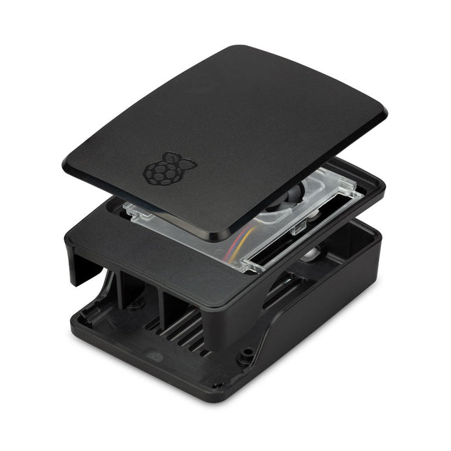
Raspberry Pi Foundation Officiële behuizing voor Raspberry Pi 5 (zwart/grijs)
De behuizing van de Raspberry Pi 5 is een verfijning van de behuizing van de Raspberry Pi 4, met verbeterde thermische eigenschappen om het hogere piekstroomverbruik van de Raspberry Pi 5 te ondersteunen. Het integreert een ventilator met variabele snelheid die wordt gevoed en bestuurd via een speciale connector op de Raspberry Pi 5.
€ 11,95€ 6,95Beste prijs
-

SEQURE SEQURE HT140 (2-in-1) SMD Soldeer- & Desoldeerpincet
De SEQURE HT140 is een zeer veelzijdige 2-in-1 soldeerbout die de functionaliteit van een hete pincet en een soldeerbout combineert. Hij is speciaal ontworpen voor nauwkeurig SMD-soldeer- en desoldeerwerk. Met onafhankelijke regeling voor enkelzijdige verhitting werkt hij als een traditionele soldeerbout wanneer hij is uitgerust met een standaardpunt. Wanneer hij is geconfigureerd voor dubbelzijdige verhitting, transformeert hij in een hete pincet – perfect voor het efficiënt en nauwkeurig verwijderen van SMD-componenten. Kenmerken Werktemperatuur: 50-500°C Ondersteunt meerdere voedingsingangen: PD 3.1/3.0/2.0, QC 3.0/2.0, (5-28 V DC), LiPo-batterijen en stroomadapters. De HT140 combineert een soldeerpincet met een soldeerbout, met onafhankelijke enkel- of dubbelzijdige verwarming. Gebruik hem als soldeerbout met een punt, of als soldeerpincet voor eenvoudig desolderen van SMD. Spanning en stroomsterkte kunnen worden aangepast op basis van de stroombron. Beschikt over dubbele temperatuurregeling, voorinstellingen, snelle temperatuurverhoging en fijnafstelling. 128 x 32 OLED-scherm met instelbare helderheid en oriëntatie. Hoognauwkeurig verwarmingselement met een nauwkeurigheid van ±1%. Smelt soldeer in slechts 2 seconden. Slimme stand-by-, slaap- en wekfuncties verlengen de levensduur van de punt en verhogen de efficiëntie. Ondersteunt temperatuurkalibratie en -compensatie voor nauwkeurig werk. Inclusief een hittebestendige PD 150 W siliconenkabel van 1,5 m en een stevig, volledig metalen HT-station. Verwisselbare punten en verstelbare hoeken voor diverse SMD-soldeertaken. Specificaties Werkspanning 5-28 V DC Maximaal vermogen 140 W Werktemperatuur 50-500°C Smelttijd tin 2 s Interfacetype USB-C, DC5525 Voeding PD 3.1/3.0/2.0, QC 3.0/2.0, 28 V DC max Display 128 x 32 OLED Firmware-upgrade Ja Menutalen Engels, Russisch, Chinees Afmetingen 160 x 27 x 17,5 mm Gewicht 50 g Inbegrepen 1x SEQURE HT140 Host 2x HT140-IS Conisch gebogen desoldeerstiften 1x HT Station 1x Accessoirepakket 1x Opbergtas 1x 65 W PD Voeding (EU, VK & VS) 1x 24 W PD Siliconen Draad (1,5 m) 1x GND Draad Accessoire Kit (1,8 m) Downloads Manual Firmware V1.04
€ 119,95€ 99,95Beste prijs
-
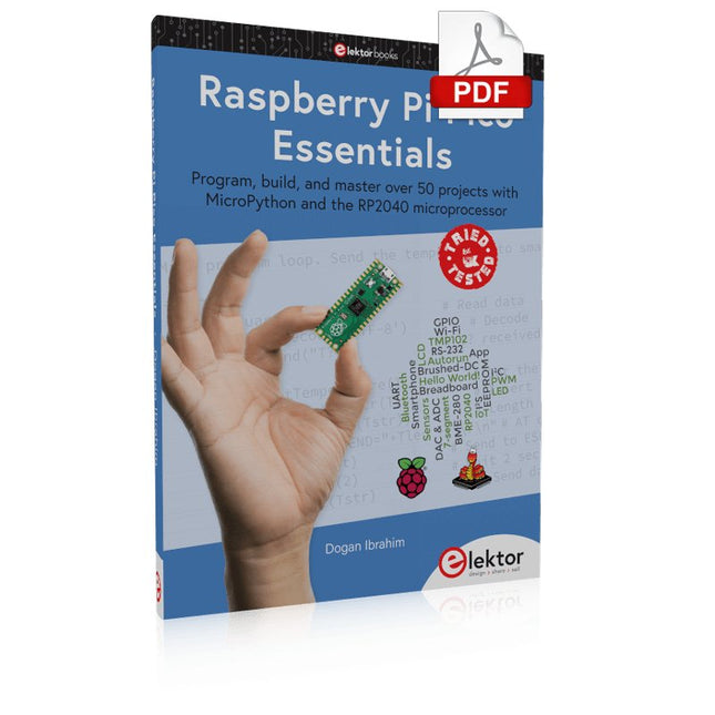
Elektor Digital Raspberry Pi Pico Essentials (E-book)
Program, build, and master over 50 projects with MicroPython and the RP2040 microprocessor The Raspberry Pi Pico is a high-performance microcontroller module designed especially for physical computing. Microcontrollers differ from single-board computers, like the Raspberry Pi 4, in not having an operating system. The Raspberry Pi Pico can be programmed to run a single task very efficiently within real-time control and monitoring applications requiring speed. The ‘Pico’ as we call it, is based on the fast, efficient, and low-cost dual-core ARM Cortex-M0+ RP2040 microcontroller chip running at up to 133 MHz and sporting 264 KB of SRAM, and 2 MB of Flash memory. Besides its large memory, the Pico has even more attractive features including a vast number of GPIO pins, and popular interface modules like ADC, SPI, I²C, UART, and PWM. To cap it all, the chip offers fast and accurate timing modules, a hardware debug interface, and an internal temperature sensor. The Raspberry Pi Pico is easily programmed using popular high-level languages such as MicroPython and or C/C++. This book is an introduction to using the Raspberry Pi Pico microcontroller in conjunction with the MicroPython programming language. The Thonny development environment (IDE) is used in all the projects described. There are over 50 working and tested projects in the book, covering the following topics: Installing the MicroPython on Raspberry Pi Pico using a Raspberry Pi or a PC Timer interrupts and external interrupts Analogue-to-digital converter (ADC) projects Using the internal temperature sensor and external temperature sensor chips Datalogging projects PWM, UART, I²C, and SPI projects Using Wi-Fi and apps to communicate with smartphones Using Bluetooth and apps to communicate with smartphones Digital-to-analogue converter (DAC) projects All projects given in the book have been fully tested and are working. Only basic programming and electronics experience is required to follow the projects. Brief descriptions, block diagrams, detailed circuit diagrams, and full MicroPython program listings are given for all projects described. Readers can find the program listings on the Elektor web page created to support the book.
€ 32,95
Leden: € 29,66
-

Elektor Mars/Avril 2026 (FR)
Le téléchargement intégral de ce numéro est disponible pour nos membres GOLD et GREEN sur le site Elektor Magazine ! Pas encore membre ? Cliquez ici. programmation PIO sur le Raspberry Pi PicoNeuf instructions, de multiples possibilités l'IA en ligne de commandeDéveloppement, compilation et validation de projets embarqués depuis le terminal le Scrutiny DebuggerDéboguer, visualiser et tester du code C/C++ embarqué carte breakout Sigfox (1)Développement d’une BoB radio alimentation à faible bruit (2)Construction, assemblage et mise en œuvre pratique générateur de signaux simple basé sur le RP2040Signaux analogiques et numériques à la découverte du futur de la domotique avec Matter et l’IA EdgeLes dernières versions de Matter et l’essor de l’IA en périphérie de réseau (edge) donnent-ils enfin aux ingénieurs les outils nécessaires pour construire les maisons intelligentes et parfaitement intégrées promises aux utilisateurs ? capteurs de pression différentielleLa maintenance prédictive appliquée aux systèmes CVC la sécurité dès la conceptionPrincipes d’ingénierie pour limiter les défaillances la sécurité des systèmes embarqués n’est plus une option la CRA et la PQC redéfinissent les priorités de la sécurité embarquéePourquoi même les petites entreprises IoT et industrielles doivent prévoir une mise à niveau embedded world 2026Entretien avec Benedikt Weyerer, directeur d’embedded world prise en main du bus I3CUtilisation de matériel de ST et Microchip le projet BLEnkyPrototypage rapide d’applications Bluetooth Low Energy modulation de largeur d’impulsionDu thermostat tout ou rien à un signal analogique continu filtré audiotroniqueDes circuits audio agréables à l’écoute, à réaliser soi-même sur le vifLisez donc le manuel ! carte émetteur-récepteur audio ESP32 (4)Réglage des horloges et une option filaire 2026 : une odyssée de l’IAConséquences du vibe coding charge CC symétriqueCharge CC symétrique, statique ou dynamique comptage de visages avec MaixCAMUne méthode simple pour estimer la taille d’un public
€ 16,50
-

Elektor 09-10/2026 (DE)
Diese Ausgabe steht allen GOLD- und GREEN-Mitgliedern auf der ElektorMagazine-Website zum Download bereit! Sie sind noch kein Mitglied? Hier klicken! Der ESP-BLASTEine Mini-Raketendrohne mit ESP32, die über 100 km/h erreicht Wireless Workshop (1)Freigeschaltetes Funkmodul: 433-MHz-CC1101-Sub-GHz-Transceiver AM-Sendermit Rechteck-/Sinuswellengenerator auf Raspberry Pi Pico STM32Cube Innovations ChallengeTreten Sie mit Ihrem besten STM32C5-Design an CoffeeCallerWie ein langer Flur zu einer maßgefertigten Mesh-Netzwerk-Platine führte AudiotronicsKlirrfaktor Elektor ist 65Projekte aus früheren September/Oktober-Ausgaben Geräteortung durch Bluetooth Channel SoundingZentimetergenaue Entfernungsmessung im IoT der nächsten Generation 2026: Eine KI-OdysseeQuantencomputing ist nicht die nächste GPU Cloud-Schutz durch Edge-Sicherheit Erste Erfahrungen mit dem HackRF ProPraktische Tests mit der neuen SDR-Hardware Herausforderung ElektromobilitätEffiziente Lötlösungen für moderne Fahrzeugtechnik Modem-Update von GPRS/2G auf LTE/4Gam Beispiel einer Funk-Alarmzentrale Loop-Antenne mit RF BricksTeil 1: Kurzwellen-Antenne mit einstellbarer Richtwirkung im Selbstbau Internetradio-zu-AM-KonverterVerwendung eines ESP32-S3 als Sender Projekt 2.0 mioty – ein ÜberblickLPWAN à la Fraunhofer Werkbank-WeisheitPraktische Tipps von Experten Walter, das kompakte IoT-ModulTeil 2: Zugriff auf Wetter- und Datendienste
€ 15,90
-

Miniware Miniware MDP-P906 Digital Power Supply (300 W)
De MDP-P906 heeft een ingebouwde ventilator en een maximaal uitgangsvermogen van 300 W, wat toereikend is voor een breed scala aan testbehoeften en toepassingen. Via 2,4 GHz draadloze communicatie kan hij worden aangesloten op de MDP-M01 Smart Digital Monitor module om daarmee een flexibele combinatie van meerdere kanalen van 300 W per kanaal te kunnen realiseren. De MDP-P906 heeft een basis, stabiliteit en betrouwbaarheid die te vergelijken is met een professionele voeding. Hij kan puur stroom leveren én krachtige functies hieraan toevoegen, zoals programmeerbare uitgang, getimede uitgang, getimede regeling, automatische compensatie, boost modus, enz. Dit maakt hem tot een kosteneffectieve, slimme en op maat programmeerbare lineaire DC-voeding. De MDP-P906 heeft een zorgvuldig CNC-gefreesde aluminium behuizing, met verfijnde afwerking, eigentijds, bescheiden en prachtig uiterlijk. Hij wijkt hiermee volledig af van het standaard uiterlijk van een traditionele desktop voeding. Door een stackable modulair ontwerp en de draadloze communicatie kan de MDP-P906 onafhankelijk of onderling gekoppeld worden gebruikt, zowel in de normale werkruimte als bij onderhoud op locatie. De MDP-P906 is een perfecte oplossing voor elektrotechnici, met name servicemonteurs, om bij verschillende situaties en toepassingen de stroom te leveren. Ingebouwde stille ventilator, instant cooling, voor een stabiele en efficiënte output! Slimme lineaire compensatie, constante spanning & constante stroom Positieve en negatieve output, series boost, parallelle stroomverdeling Toepassingen Universele tests en onderwijsexperimenten in R&D laboratoria Onderhoud van digitale producten Eigendomsverificatie en foutdiagnose van apparaten en circuits Noodstroomvoorziening voor modelvliegtuigen en voertuigen Voedingen testen van RF en microgolfcircuits of -modules Kwaliteitscontrole en kwaliteitsinspectie Zuivere voeding voor zeer nauwkeurige digitaal-analoge hybride circuits en Hi-Fi audioapparaten Specificaties Input DC 4.2-30 V / 14 A (Max)QC 3.0/PD2.0, 20 V / 5 A (Max) Uitgang 0-30 V / 0-10 A, 300 W (Max) Conversie efficiëntie 95% Output resolutie 10 mV / 2 mA, tot 1 mV / 1 mA via Display Control module Output nauwkeurigheid 0,03%+5 mV0,05%+2 mV Adjustment rate Load adjustment rate <±0,01%Power adjustment rate <±0,01% Ripple en noise <250 uVrms, 3 mVpp; 2 mArms Transient response <4 uS Beveiligingen Te hoge voedingsspanning, onderspanning, omgekeerd aansluiten, te hoge uitgangsstroom, retourstroom en oververhitting Overig Automatisch afsluiten en naar micro-power modeOndersteuning van USB firmware upgrade Afmetingen 112 x 66 x 20 mm Gewicht 181 g Inbegrepen 1x MDP-P906 digitale voeding 2x uitgangskabel 1x gebruikershandleiding Downloads User Manual v1.1 Firmware v1.32
€ 171,95
-

Raspberry Pi Foundation FPC Display Cable for Raspberry Pi 5 (300 mm)
Raspberry Pi 5 provides two four-lane MIPI connectors, each of which can support either a camera or a display. These connectors use the same 22-way, 0.5 mm-pitch “mini” FPC format as the Compute Module Development Kit, and require adapter cables to connect to the 15-way, 1 mm-pitch “standard” format connectors on current Raspbery Pi camera and display products.These mini-to-standard adapter cables for cameras and displays (note that a camera cable should not be used with a display, and vice versa) are available in 200 mm, 300 mm and 500 mm lengths.
€ 2,95€ 1,18Beste prijs
-

Raspberry Pi Foundation Das offizielle Raspberry Pi-Handbuch für Einsteiger (5. Auflage)
Vollständig aktualisiert für Raspberry Pi 5 Raspberry Pi ist ein kleiner, cleverer, in Großbritannien hergestellter Computer, der voller Potenzial steckt. Der Raspberry Pi basiert auf einem energieeffizienten Prozessor der Desktop-Klasse und soll Ihnen dabei helfen, das Programmieren zu erlernen, herauszufinden, wie Computer funktionieren, und Ihre eigenen erstaunlichen Dinge zu bauen. Dieses Buch wurde geschrieben, um Ihnen zu zeigen, wie einfach der Einstieg ist. Lernen Sie, wie Sie: Richten Sie Ihren Raspberry Pi ein, installieren Sie sein Betriebssystem und beginnen Sie mit der Nutzung dieses voll funktionsfähigen Computers. Starten Sie Codierungsprojekte mit Schritt-für-Schritt-Anleitungen für die Programmiersprachen Scratch 3, Python und MicroPython. Experimentieren Sie mit der Verbindung elektronischer Komponenten und haben Sie Spaß beim Erstellen erstaunlicher Projekte. Neu in der 5. Auflage: Aktualisiert für die neuesten Raspberry Pi-Computer: Raspberry Pi 5 und Raspberry Pi Zero 2 W. Deckt das neueste Raspberry Pi OS ab. Enthält ein neues Kapitel über den Raspberry Pi Pico. Downloads GitHub
€ 24,95€ 9,98Beste prijs
-
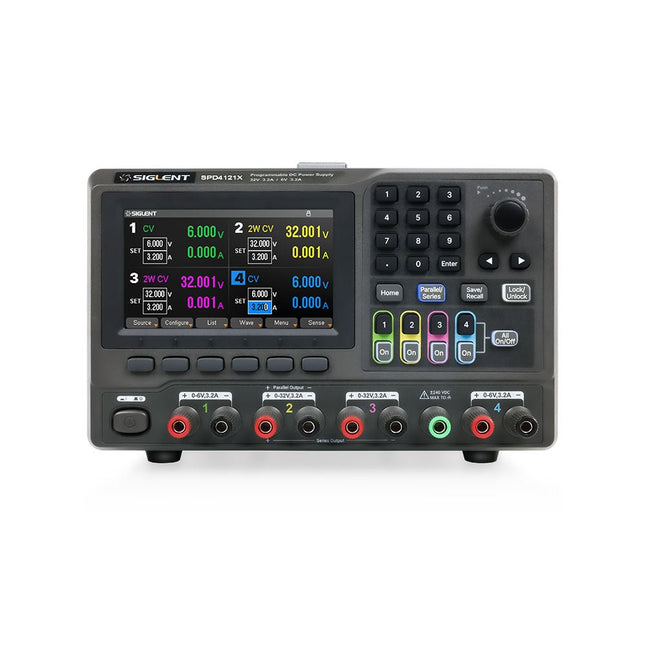
Siglent Siglent SPD4121X 4-kanaals Voeding (285 W)
The Siglent SPD4121X is a 4-channel DC Linear Programmable Power Supply equipped with a 4.3-inch TFT-LCD display, friendly human-machine interface, and excellent performance indicators. Real-time waveform display provides engineers with an informative user interface. SPD4121X offers a total output power of 285 W with a resolution of 1 mV/1 mA. The maximum voltage and current for each channel are as follows: CH1: 15 V/1.5 A CH2: 12 V/10 A CH3: 12 V/10 A CH4: 15 V/1.5 A Kenmerken Rated output power: 285 W Rated voltage: 32 V, 12 V, 30 V Up to four high-precision power supplies with independent controllable outputs, supporting CH2 and CH3 series and parallel connections Clear graphical interface with waveform and timer display modes 5-digit voltage and current display with minimum resolution of 1 mV, 1 mA Fast output response time: <50us The high current channel support remote voltage compensation sense function. The maximum compensation voltage is 0.6 V Overvoltage protection and overcurrent protection or safe and accurate operation Equipped with a 4.3-inch TFT-LCD display (480 x 272 resolution) USB and LAN standard communication USB-GPIB module is optional Excellent channel density with up to 4 channels in a 3U half rack package Internal data storage for setups and parameters Embedded Web Server with instrument communication that doesn’t require software installation Fully SCPI programming command set support as well as a LabView driver for remote control and system automation Specificaties SPD4323X SPD4121X SPD4306X Channel Output CH1: Voltage 0 to 6 V Current 0 to 3.2 ACH2: Voltage 0 to 32 V Current 0 to 3.2 ACH3: Voltage 0 to 32 V Current 0 to 3.2 ACH4: Voltage 0 to 6 V Current 0 to 3.2 A CH1: Voltage 0 to 15 V Current 0 to 1.5 ACH2: Voltage 0 to 12 V Current 0 to 10 ACH3: Voltage 0 to 12 V Current 0 to 10 ACH4: Voltage 0 to 15 V Current 0 to 1.5 A CH1: Voltage 0 to 15 V Current 0 to 1.5 ACH2: Voltage 0 to 30 V Current 0 to 6 ACH3: Voltage 0 to 30 V Current 0 to 6 ACH4: Voltage 0 to 15 V Current 0 to 1 A Resolution 1 mV, 1 mA 1 mV, 1 mA 1 mV, 1 mA Setting Accuracy Voltage: ±(0.03% of reading+10) mV, Current: ±(0.3% of reading+10) mA Voltage: ±(0.03% of reading+10) mV, Current: ±(0.3% of reading+10) mA Voltage: ±(0.03% of reading+10) mV, Current: ±(0.3% of reading+10) mA Readback Accuracy Voltage: ±(0.03% of reading+10) mV, Current: ±(0.3% of reading+10) mA Voltage: ±(0.03% of reading+10) mV, Current: ±(0.3% of reading+10) mA Voltage: ±(0.03% of reading+10) mV, Current: ±(0.3% of reading+10) mA Display 4.3" TFT-LCD 5-digit voltage and current display 4.3" TFT-LCD 5-digit voltage and current display 4.3" TFT-LCD 5-digit voltage and current display Output power 240 W 285 W 400 W Inbegrepen 1x Siglent SPD4121X Power Supply 1x Power cord (EU) 1x Output test cord (3 A) 1x USB cable 1x Quick start guide Downloads Datasheet Manual Quick start
€ 871,20


