
Zoekresultaten voor "toolcraft OR st OR 100d OR digital OR soldering OR station OR 100 OR w"
-
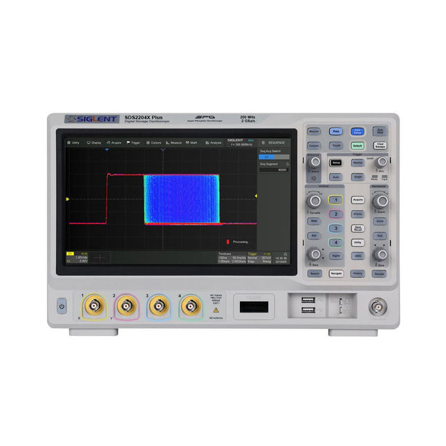
Siglent Siglent SDS2204X Plus 4-ch Oscilloscope (200 Mhz)
Siglent's SDS2000X Plus series Digital Storage Oscilloscopes are available in bandwidths of 100 MHz, 200 MHz, and 350 MHz, have a maximum sample rate of 2 GSa/s, a maximum record length of 200 Mpts/ch, and up to 4 analog channels + 16 digital channels mixed-signal analysis ability. The SDS2000X Plus series employs Siglent’s SPO technology with a maximum waveform capture rate of up to 120,000 wfm/s (normal mode, up to 500,000 wfm/s in Sequence mode), 256-level intensity grading display function plus a color temperature display mode. It also employs an innovative digital trigger system with high sensitivity and low jitter. The trigger system supports multiple powerful triggering modes including serial bus triggering. History waveform recording, Sequence acquisition, Search and Navigate functions allow for extended waveform records to be captured, stored, and analyzed. An impressive array of measurement and math capabilities, options for a 50 MHz waveform generator, as well as serial decoding, mask test, bode plot, and power analysis are also features of the SDS2000X Plus. A 10-bit acquisition mode helps to satisfy applications that require more than 8-bit resolution. The large 10.1’’ capacitive touch screen supports multi-touch gestures, while the remote web control, mouse and external keyboard support greatly improve the operating efficiency of the SDS2000X Plus. Features 100 MHz, 200 MHz, 350 MHz (upgradable to 500 MHz) models Real-time sampling rate up to 2 GSa/s Record length up to 200 Mpts Serial bus triggering and decoder, supports I²C, SPI, UART, CAN, LIN, CAN FD, FlexRay, I²S and MIL-STD-1553B Provide 10 bit mode, Vertical and Horizontal Zoom Capacitive touch screen supports multi-touch gestures Siglent SDS2000X Plus Oscilloscopes SDS2102X Plus SDS2104X Plus SDS2204X Plus SDS2354X Plus Bandwidth 100 MHz 100 MHz 200 MHz 350 MHz Channels 2 4 4 4 Real-time sampling rate 2 GSa/s 2 GSa/s 2 GSa/s 2 GSa/s Capture rate 120,000 wfm/s 120,000 wfm/s 120,000 wfm/s 120,000 wfm/s Memory depth 200 Mpts/ch 200 Mpts/ch 200 Mpts/ch 200 Mpts/ch Included Siglent SDS2204X Plus Oscilloscope Passive probes Power cord USB cable Manual Downloads Datasheet Manual Quick guide User manual Firmware
€ 1.838,23
-

Siglent Siglent SDS1104X-E 4-kanaals Oscilloscoop (100 MHz)
The Siglent SDS1104X-E employs a new generation of SPO (Super Phosphor Oscilloscope) technology that provides excellent signal fidelity and performance. The system noise is also lower than similar products in the industry. It comes with a minimum vertical input range of 500 uV/div, an innovative digital trigger system with high sensitivity and low jitter, and a waveform capture rate of 400,000 frames/ sec (sequence mode). The SDS1104X-E also employs a 256-level intensity grading display function and a color temperature display mode not found in other models in this class. SIGLENT’s latest oscilloscopes offering supports multiple powerful triggering modes including serial bus triggering. Serial decoding is free and includes IIC, SPI, UART, CAN, and LIN. History waveform recording and sequential triggering enable extended waveform recording and analysis. Another powerful addition is the new 1 Mpt FFT math function that gives the SDS1104X-E very high frequency resolution when observing signal spectra. Kenmerken Intelligent trigger: Edge, Slope, Pulse Width, Window, Runt, Interval, Timeout (Dropout), and Pattern Free Serial bus triggering and decoding:IIC, SPI, UART, RS232, CAN, and LIN Video triggers and supports HDTV Low background noise and 500 ?V / div to 10 V / div voltage scales 10 types of one-button shortcuts, supports Auto Setup, Default, Cursors, Measure, Roll, History, Display/Persist, Clear Sweep, Zoom and Print Segmented acquisition (Sequence) mode, dividing the maximum record length into multiple segments (up to 80,000), according to trigger conditions set by the user, with a very small dead time segment to capture the qualifying event. History waveform record (History) function, the maximum recorded waveform length is 80,000 frames Automatic measurement function on 38 parameters, supports Statistics, Gating measurement, Math measurement, History measurement and Ref measurement 1 Mpts FFT True measurement and math can use all 14 Mpts of memory Preset key can be customized for user settings or factory “defaults” Security Erase mode Highspeed hardware based Pass/ Fail function Large 7-inch TFT-LCD display with 800 * 480 resolution Multiple interface types: USB Host, USB Device (USB-TMC), LAN (VXI-11), Pass / Fail, Trigger Out Supports SCPI remote control commands Multi-language display and embedded help Browser control/onboard webpage for software free monitoring (4 channel models only) Inbegrepen 1x Siglent SDS1104X-E Oscilloscope 4x 100 MHz probes 1x Guarantee Card 1x Power Cord 1x USB Cable 1x Quick Start Guide Downloads Datasheet Manual Programming Guide
€ 508,71
-
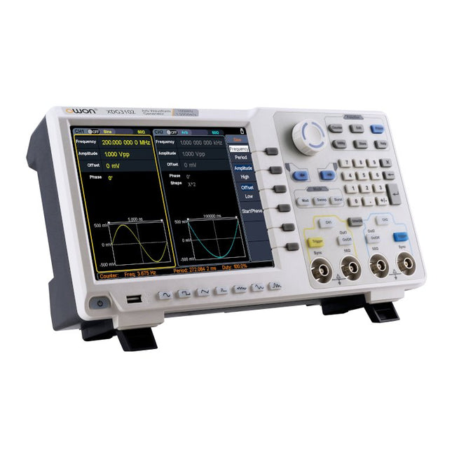
OWON OWON XDG3102 2-kanaals Arbitrary Waveform Generator (100 MHz)
Kenmerken Advanced DDS technology, up to 250MHz frequency output 1.25GS/s sampling rate, and 1 μHz frequency resolution Up to 1M arbitrary waveform length Vertical resolution: 14 bits Comprehensive waveform output: 6 groups waveforms, and 152 group built-in arbitrary waveforms Comprehensive modulation options: AM, FM, PM, FSK, 3FSK, 4FSK, PSK, OSK, ASK, BPSK, PWM, sweep, and burst High-accuracy frequency counter integrated, ranging from 100mHz till 200MHz SCPI and LabVIEW supported 8'' 800 x 600 pixels touch screen LCD Specificaties XDG3102 Channel 2 Frequency Output 100MHz Sample Rate 1.25GSa/s Vertical Resolution 14 bits Waveform Standard Waveform sine, square, pulse, ramp, noise, and harmonic Arbitrary Waveform exponential rise, exponential fall, sin(x)/x, step wave, and others, total of 150 built-in waveforms, and user-defined arbitrary waveform Frequency (resolution 1μHz) Sine 1μHz - 100MHz Square 1μHz - 40MHz Pulse 1μHz - 25MHz Ramp 1μHz - 5MHz Harmonic 1μHz - 50MHz Noise 120MHz (-3dB, typical) Arbitrary Waveform built-in waveform: 1uHz - 15MHzuser-defined waveform: 1uHz - 50MHz Accuracy ±1ppm, 0°C - 40°C Amplitude Amplitude (50Ω) 1mVpp - 10Vpp (≤40MHz); 1mVpp - 5Vpp (≤80MHz) 1mVpp - 2.5Vpp (≤120MHz); 1mVpp - 1Vpp (≤250MHz) Amplitude(high impedance) 2mVpp - 20Vpp (≤40MHz); 2mVpp - 10Vpp (≤80MHz); 2mVpp - 5Vpp (≤120MHz); 2mVpp - 2Vpp (≤250MHz) Resolution 1mV or 4 digits DC Offset Range (50Ω) ±(5 Vpk - Amplitude Vpp/2) Range (high-Z, open circuit) ±(10 Vpk - Amplitude Vpp/2) Accuracy ±(1% of |setting| + 1mV + Amplitude Vpp x 0.5%) Resolution 1mV or 4 digits Load Impedance 50Ω (typical) Accuracy ±(1% of setting + 1 mVpp) (typical, 1kHz sine, 0V offset) Sine Wave Spectrum Purity Harmonic Distortion Typical (0dB) DC - 1MHz: <-65dBc 1MHz - 10MHz: <-60dBc 10MHz - 120MHz: <-50dBc 120MHz - 200MHz: <-45dBc Total Harmonic Distortion ≤0.05 %, 10 Hz to 20 kHz, 1 Vpp Spurious (non-harmonic), Typical (0dB) ≤10MHz: <-70dBc >10MHz: <-70dBc + 6dB/ octave Phase Noise Typical (0 dBm, 10 kHz deviation) 10MHz: -110dBc/Hz Square Rise/Fall Time <5ns Overshoot <3% Duty Cycle 50.0% (fixed) Jitter (rms) 300ps + 100ppm Pulse Pulse Width 12ns - 996875s Leading/Trailing Edge Time ≤7ns Overshoot <3% Jitter (rms) 300ps + 100ppm Ramp Linearity ≤1% of peak output (typical, 1kHz, 1 Vpp, 50% symmetry) Symmetry 0% to 100% Harmonic Harmonic Order ≤16 Harmonic Type even, odd, all, user Harmonic Amplitude could be set for all the harmonics Harmonic Phase Arbitrary Waveform Length 2 points - 1M points Vertical Resolution 14 bits Minimum Rise/Fall Time <7ns Jitter (rms) 3ns Modulation Type AM, FM, PM, PWM, FSK, 3FSK, 4FSK, PSK, OSK, ASK, BPSK, sweep, and burst AM Carrier Waveform sine, square, ramp, and arbitrary (except DC) Source internal / external Modulating Waveform sine, square, ramp, noise, and arbitrary Depth 0.0% - 100.0% Modulating Frequency 2 mHz - 100 kHz FM Carrier Waveform sine, square, ramp, and arbitrary (except DC) Source internal / external Modulating Waveform sine, square, ramp, noise, and arbitrary Modulating Frequency 2 mHz - 100 kHz PM Carrier Waveform sine, square, ramp, and arbitrary (except DC) Source internal / external Modulating Waveform sine, square, ramp, noise, and arbitrary Phase Deviation 0° - 180° Modulating Frequency 2 mHz - 100 kHz PWM Carrier Waveform pulse Source internal / external Modulating Waveform sine, square, ramp, noise, and arbitrary Width Deviation 0 ~ minimum (pulse duty ratio, 100% - pulse duty ratio) Modulating Frequency 2 mHz - 100 kHz FSK / 3FSK / 4FSK Carrier Waveform sine, square, ramp, and arbitrary (except DC) Source internal / external Modulating Waveform square with 50% duty cycle Key Frequency 2 mHz - 1MHz PSK Carrier Waveform sine, square, ramp, and arbitrary (except DC) Source internal / external Modulating Waveform square with 50% duty cycle Key Frequency 2 mHz - 1MHz OSK Carrier Waveform sine, square, ramp, and arbitrary (except DC) Source internal Oscillation Time square with 50% duty cycle Key Frequency 2 mHz - 1MHz ASK Carrier Waveform sine, square, ramp, and arbitrary (except DC) Source internal / external Modulating Waveform square with 50% duty cycle Key Frequency 2 mHz - 1MHz BPSK Carrier Waveform sine, square, ramp, and arbitrary (except DC) Source internal Modulating Waveform square with 50% duty cycle Key Frequency 2 mHz - 1MHz Sweep Carrier Waveform sine, square, ramp, and arbitrary (except DC) Type linear, and log Direction up, and down Sweep Time 1 ms to 500s, ± 0.1% Trigger Source internal, external, and manual Burst Carrier Waveform sine, square, ramp, pulse, and arbitrary (except DC) Burst Count 1 to 50,000 period, infinite, gating Internal Period 10 ns - 500 s Gated Source external trigger Frequency Counter Function frequency period, +width, -width, +duty, and -duty Frequency Range 100mHz - 200MHz Frequency Resolution 7 digits Input / Output Display 8”800 x 600 pixels touch screen LCD Type frequency counter, external modulation input,external trigger input,external reference clock input / output Communication Interface USB Host, USB Device, and LAN Dimensions 340 x 177 x 90 mm Weight 2.50 kg
€ 650,00
-
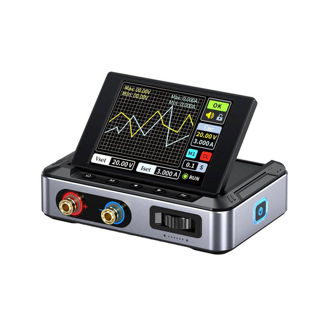
FNIRSI FNIRSI DPS150PD DC-voeding (150 W)
De FNIRSI DPS150 is een krachtige, instelbare DC-voeding met een USB-C-ingangsinterface en meerdere voedingsmodi, waardoor een nauwkeurige aanpassing van de uitgangsspanning (0-30 V) en stroom (0-5 A) mogelijk is. Het biedt een efficiënte, laag verbruik en stabiele output, uitgerust met meerdere veiligheidsbeschermingsfuncties, waaronder overspanning, overstroom, overbelasting, oververhitting en omgekeerde verbinding. Het kan flexibel worden toegepast op de seriële verbinding van meerdere apparaten, met een rijke en gebruiksvriendelijke weergave en bediening, een compact en draagbaar ontwerp en voldoet aan verschillende toepassingsbehoeften. Kenmerken 30 V, 5 A, 150 W variabel gelijkstroomvermogen met 0,01 V, 0,001 A precisie, CC/CV-modi en <20 mV rimpel om gevoelige elektronica te beschermen. Ondersteunt pc-, QC- en DC-ingangen met programmeerbare uitgangen en 6 vooraf ingestelde spannings-/stroominstellingen. Compatibel met 4 mm banaanstekkers, U-vormige aansluitingen en koperdraden voor diverse apparatuur. 8 veiligheidsmechanismen, waaronder bescherming tegen overspanning, stroom, kortsluiting en oververhitting. 2,8-inch HD IPS-scherm met 90° flip-, numerieke en curve-displays voor eenvoudige monitoring. Klein, ruimtebesparend ontwerp voor gebruik in laboratoria, reparaties en doe-het-zelf-projecten. Specificaties Ingangsspanning 5~32 V DC Ingangsstroom 100 mA-5 A Uitgangsspanning 0-30 V Uitgangsstroom 0~5 A Uitgangsvermogen 0-150 W Input way PD-snellader QC snellader Powerbank DC-voedingsadapters Bedrijfsomgeving 0-40°C Belastingsregeling 0,49% Efficiëntie bij volledige belasting 96,30% Display 2,8 inch (320 x 240) Afmetingen 106 x 76 x 28 mm Gewicht 178 g Inbegrepen 1x DPS150 voeding 2x Krokodillenklemdraden (zwart en rood) 1x C2C PD oplaadkabel 1x 100 W PD GaN-adapter (EU) 1x Micro-USB-kabel 1x Manual Downloads Manual Firmware V0.0.1
€ 95,00
-

Elektor Labs Elektor Zandklok voor Raspberry Pi Pico (incl. Laserkop Upgrade)
Dit bundel bevat de populaire Elektor zandklok voor Raspberry Pi Pico en de nieuwe Elektor laserkop upgrade, en biedt daarmee nog meer mogelijkheden om de tijd weer te geven. U kunt de actuele tijd nu niet alleen in zand "graveren", maar ook op een lichtgevende folie schrijven of groene tekeningen maken. Inhoud van de bundel Elektor Zandklok voor Raspberry Pi Pico (normale prijs: € 50) Elektor Laserkop Upgrade voor Zandklok (normale prijs: € 35) Zandklok voor Raspberry Pi (een op de Raspberry Pi Pico gebaseerde Eye Catcher) Een standaard zandklok laat meestal slechts zien hoe de tijd verstrijkt. Deze door een Raspberry Pi Pico aangestuurde zandklok toont daarentegen de exacte tijd door de vier cijfers voor uren en minuten in een zandlaag te "graveren". Na een vooraf ingestelde periode wordt het zand door twee trilmotoren vlak getrild en begint alles weer van voren af aan. Het hart van de zandklok wordt gevormd door twee servomotoren, die via een pantograafmechanisme een schrijfpen aandrijven. Een derde servomotor tilt deze pen op en neer. Het zandbakje is voorzien van twee trilmotoren om het zand weer vlak te trillen. Het elektronische deel van de zandklok bestaat uit een Raspberry Pi Pico en een RTC/driverbord met een real-time klok, plus drivercircuits voor de servomotoren. Een gedetailleerde bouwhandleiding is beschikbaar via download. Kenmerken Afmetingen: 135 x 110 x 80 mm Bouwtijd: ca. 1,5 tot 2 uur Inbegrepen 3x Voorgesneden acrylaatplaten met alle mechanische onderdelen 3x Mini servomotoren 2x Trilmotoren 1x Raspberry Pi Pico 1x RTC/driverkaart met geassembleerde onderdelen Moeren, boutjes, afstandhouders en draden voor de montage Fijnkorrelig wit zand Elektor Laserkop Upgrade voor Zandklok De nieuwe Elektor Laserkop transformeert de Elektor Zandklok in een klok die de tijd op glow-in-the-dark-film schrijft in plaats van op zand. Naast het weergeven van de tijd kan het ook worden gebruikt om kortstondige tekeningen te maken. De 5 mW laserpointer, met een golflengte van 405 nm, produceert heldergroene tekeningen op de glow-in-the-dark-film. Voor het beste resultaat gebruikt u de kit in een slecht verlichte kamer. Waarschuwing: Kijk nooit rechtstreeks in de laserstraal! De kit bevat alle benodigde componenten, maar het solderen van drie draden is vereist. Opmerking: Deze kit is ook compatibel met de originele Arduino-gebaseerde Zandklok uit 2017. Voor meer details, zie Elektor 1-2/2017 en Elektor 1-2/2018.
€ 84,95€ 69,95Beste prijs
-

Elektor Digital Elektor Mai/Juin 2021 (PDF)
SUPERCHARGEUR LIPO DIYDe l'artisanat au marché de masse60 ANS D'ELEKTORRéflexions sur six décennies d'électroniqueMULTIMÈTRE DE TABLE SIGLENT SDM3045XPINCE AMPÈREMÉTRIQUE POUR COURANT CONTINUCapteur à effet Hall + noyau de ferrite + ArduinoSTATION DE SOUDAGE 2021Facile à construire !PROPELLER 2 DE PARALLAX (2)Environnement de développement et codeWIFI POUR LE NŒUD LORA D'ELEKTORIntegrated in Home Assistant with ESPHomeMODULE CELLULAIREMême pas peur !GESTION DU TEMPS AVEC L'ESP32 ET TOGGLPratiquer le kit ESP32 Basic Core de M5StackCARTE RASPBERRY PI PICO À RP2040MICROPYTHON POUR LES MICROCONTRÔLEURSAfficheur riquiquiCONVERTISSEUR CC/CC 12 À 200 Vpour amplificateurs à tubesTRAQUEUR DE CHALEURCaméra thermique Seek Shot ProPROGRAMMATION ORIENTÉE OBJETUne brève introduction avec le C++DANS L'ANTRE DE…Kurt Diedrich et de son synthétiseur analogiqueJAVA SUR RASPBERRY PIPartie 1: les broches GPIOINTERRUPTEURS DIPCORRECTIONS, MISES À JOUR ET COURRIER DES LECTEURSDU TOUT-JETABLE AU TOUT-RÉPARABLE ?La réponse législative de l'UEPOINT D'OMELETTE SANS CASSER D'ŒUFSLe grand livre des gaffesMICRO-PROFESSORApprentissage de l'assembleur sur Z80DÉMARRER EN ÉLECTRONIQUE… (7)…est moins difficile qu'on ne l'imagine ! Même lorsqu'il s'agit de condensateurs.HEXADOKUcasse-tête pour elektorniciens
€ 10,95
-

Red Pitaya Red Pitaya STEMlab 125-14 PRO Gen 2 Starter Kit (incl. Boek)
Deze bundel bevat de Red Pitaya STEMlab 125-14 PRO Gen 2 Starter Kit en het nieuwe boek "Experimenteren met Red Pitaya STEMlab Gen 2". De Red Pitaya STEMlab 125-14 PRO Gen 2 Starter Kit is een krachtig en flexibel platform voor signaalverwerking, data-acquisitie en elektronische meettoepassingen. Deze kit is ontworpen voor ingenieurs, ontwikkelaars, onderzoekers en docenten en biedt alles wat nodig is om te beginnen met het bouwen van geavanceerde meet- en besturingssystemen. De kern van de kit wordt gevormd door het STEMlab 125-14 PRO Gen 2-bord, een geüpgradede en ultralichte ontwikkeling. Aangedreven door de Xilinx Zynq-7010 SoC met 512 MB RAM, combineert het de programmeerbaarheid van een FPGA met de verwerkingskracht van een ARM-processor om hoogwaardige instrumentatie en aangepaste signaalverwerkingsoplossingen mogelijk te maken. Het bord biedt een 14-bits ADC- en DAC-resolutie, een bemonsteringsfrequentie van 125 MS/s, een ingangsbereik van ±20 V en een bandbreedte tot 60 MHz. Dankzij de verbeterde ruisarme analoge front-end, USB-C-connectiviteit en het compacte ontwerp is het geschikt voor veeleisende toepassingen zoals RF-ontwikkeling, radarsystemen, fotonica-onderzoek, softwaregedefinieerde radio (SDR) en industriële automatisering. De Starter Kit bevat alle essentiële accessoires voor onmiddellijk gebruik: een microSD-kaart met vooraf geïnstalleerd besturingssysteem, voeding, ethernetkabel voor toegang op afstand, twee 100 MHz-oscilloscoopprobes en SMA-naar-BNC-adapters voor flexibele signaalaansluitingen. De Red Pitaya STEMlab 125-14 PRO Gen 2 Starter Kit is een uitstekend platform voor rapid prototyping, FPGA-ontwikkeling, meetinstrumentatie en geavanceerde elektronica-experimenten. Kenmerken 14-bits ADC- en DAC-resolutie 125 MS/s samplingfrequentie ±20 V ingangsbereik Tot 60 MHz bandbreedte Xilinx Zynq-7010 SoC (FPGA + ARM-processor) 512 MB RAM Ruisarme analoge front- en back-ends Toepassingen RF-ontwikkeling en -testen Radar- en draadloze systemen Software Defined Radio (SDR) Fotonica en optisch onderzoek Industriële automatisering en besturingssystemen Signaalanalyse en instrumentatie Snel prototypen van elektronische meetsystemen Specificaties Processor Dual-core ARM Cortex-A9 FPGA AMD Xilinx Zynq-7010 SoC RAM 512 MB (4 Gb) Opslag microSD-kaart (tot 32 GB) Besturingssysteem Linux-gebaseerd Red Pitaya OS ADC-resolutie 14-bits DAC Resolutie 14-bits Bandbreedte 60 MHz (DC) Sampling rate 125 MS/s Analoge ingangskanalen 2 Analoge uitgangskanalen 2 Ingangsspanningsbereik ±1 V (LV) / ±20 V (HV) Ingangsimpedantie 1 MΩ / 10 pF Uitgangsspanningsbereik ±1 V Ethernet 1x Gigabit Ethernet (RJ45) USB 2x USB-C 2.0 (voor voeding en console) Digitale I/O 16x GPIO (3,3 V) Communicatie-interfaces I²C, SPI, UART, CAN Voeding 5 V/3 A via USB-C Afmetingen 106,8 x 60,0 x 17,9 mm Inbegrepen 1x Red Pitaya STEMlab 125-14 PRO Gen 2 Board 2x 100 MHz oscilloscoopprobes 2x SMA-naar-BNC-adapters 1x microSD-kaart met voorgeïnstalleerd besturingssysteem 1x USB-C-voeding 1x Ethernetkabel Downloads Documentation Schematics Book: Experimenting with Red Pitaya STEMlab Gen 2 Met dit nieuwe boek gaat Red Pitaya verder dan een veelzijdig board. Het wordt een krachtig laboratoriuminstrument voor nauwkeurige metingen, analyse en besturing. Van de basisprincipes van elektronische projectontwikkeling, monitoring, besturing en ontwerp tot testen: dit boek begeleidt u stap voor stap door alles wat u moet weten om het volledige potentieel van de Red Pitaya-hardware en -software te benutten. Het boek presenteert real-time, FPGA-gebaseerde projecten die op een PC worden ontwikkeld met de Vivado-omgeving en vervolgens naar de Red Pitaya worden overgebracht voor uitvoering en testen. U leert over verbeterde prestaties, uitgebreide I/O-mogelijkheden, verbeterde FPGA-functionaliteiten en geavanceerde connectiviteitsopties die nieuwe mogelijkheden openen voor nauwkeurige metingen, monitoring en besturing in uw embedded toepassingen. In dit boek ontdekt u: Een diepgaande verkenning van de Red Pitaya-architectuur en het hardwareontwerp Elektronische experimenten met Red Pitaya voor meting en monitoring Praktische projecten met de programmeertaal Python Praktische richtlijnen voor FPGA-programmering met Red Pitaya Red Pitaya FPGA-projecten met Verilog HDL in de Vivado IDE Praktisch ontwerp van elektronische projecten inclusief meting en testen Stapsgewijze voorbeelden die theorie en praktijk met elkaar verbinden Of u nu uw eigen elektronische schakelingen ontwerpt, tools voor signaalanalyse ontwikkelt of real-time besturings- of monitoringssystemen creëert, dit boek biedt u de kennis en het vertrouwen om het Red Pitaya-platform volledig te leren kennen en aan te passen.
€ 799,00
Beste prijs
-

Elektor Digital Elektor Januari/Februari 2021 (PDF)
ZELFBOUW LIPO- SUPERCHARGER-BUNDELLiPo-lader, -booster en -beveiliging van GreatScott en Elektor MTHECAM – DE MINI-THERMOCAMERAeenvoudige warmtebeeldcamera voor het lokaliseren van hot- en coldspots REVIEW: WELLER-SOLDEERSTATION WE 1010 ELECTRONICA FAST FORWARD 2020 – DE WINNAARS I2S TESTSIGNAALGENERATOR MET AVR-MICROCONTROLLER32-bit 1-kHz digitale sinus, fs 192 kHz, niveau instelbaar van 0 tot –110 dB DOMOTICA MET DE RASPBERRY PIRPi luistert op 433,92 MHz SCHAKELINGEN ONLINE SIMULEREN UIT HET LEVEN GEGREPENde dunne grens tussen orde en chaos ALLE BEGIN......hoeft niet zo moeilijk te zijn OOST WEST LAB BESTeen blik in het allerheiligste, waar interessante projecten worden geboren VERBIND UW THERMOSTAAT MET ESPHOMEeen poging om domotica op de juiste manier te doen DEVELOPER’S ZONEtips & trucs, vakkunstigheden en andere nuttige informatie WIE HET KLEINE NIET EERTuit de ideeënbus van Elektor RASPBERRY PI FULL STACKRPi en RF24 als hart van een sensornetwerk MULTITASKING MET DE ESP32 (6)event groups MEERKANAALS POWER ANALYZERtot 3 kanalen, met grafisch en alfanumeriek display ANALOGE ELEKTRONICA ONTWERPENcase-study #2 – deel 3: passieve filters REVIEW: DRAADLOZE MEETMODULE JOY-IT VAX-1030 NIEUWE LCR-METER 50 HZ – 2 MHZ (DEEL 2)bediening, kalibratie en programmeren van de firmware ERROR ANALYSIStips en trucs: spanningsregelaars, PCB-ontwerp en meer HET OPEN HARDWARE OBSERVATORYcommunitygebaseerde beoordeling van open source-hardware JAVA OP DE RASPBERRY PIeen vraaggesprek met Frank Delporte DATA-ANALYSE EN KUNSTMATIGE INTELLIGENTIE IN PYTHONechte gegevens interpreteren met NumPy, pandas en scikit-learn INTERACTIEFcorrecties & updates || brieven van lezers ONZE COMMUNITY IN CIJFERS KENNISMAKING MET DE PARALLAX PROPELLER 2 (DEEL 1)inleiding HEXADOKU
€ 9,95
-
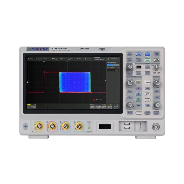
Siglent Siglent SDS2354X Plus 4-ch Oscilloscope (350 MHz)
Siglent's SDS2000X Plus series Digital Storage Oscilloscopes are available in bandwidths of 100 MHz, 200 MHz, and 350 MHz, have a maximum sample rate of 2 GSa/s, a maximum record length of 200 Mpts/ch, and up to 4 analog channels + 16 digital channels mixed-signal analysis ability. The SDS2000X Plus series employs Siglent’s SPO technology with a maximum waveform capture rate of up to 120,000 wfm/s (normal mode, up to 500,000 wfm/s in Sequence mode), 256-level intensity grading display function plus a color temperature display mode. It also employs an innovative digital trigger system with high sensitivity and low jitter. The trigger system supports multiple powerful triggering modes including serial bus triggering. History waveform recording, Sequence acquisition, Search and Navigate functions allow for extended waveform records to be captured, stored, and analyzed. An impressive array of measurement and math capabilities, options for a 50 MHz waveform generator, as well as serial decoding, mask test, bode plot, and power analysis are also features of the SDS2000X Plus. A 10-bit acquisition mode helps to satisfy applications that require more than 8-bit resolution. The large 10.1’’ capacitive touch screen supports multi-touch gestures, while the remote web control, mouse and external keyboard support greatly improve the operating efficiency of the SDS2000X Plus. Features 100 MHz, 200 MHz, 350 MHz (upgradable to 500 MHz) models Real-time sampling rate up to 2 GSa/s Record length up to 200 Mpts Serial bus triggering and decoder, supports I²C, SPI, UART, CAN, LIN, CAN FD, FlexRay, I²S and MIL-STD-1553B Provide 10 bit mode, Vertical and Horizontal Zoom Capacitive touch screen supports multi-touch gestures Siglent SDS2000X Plus Oscilloscopes SDS2102X Plus SDS2104X Plus SDS2204X Plus SDS2354X Plus Bandwidth 100 MHz 100 MHz 200 MHz 350 MHz Channels 2 4 4 4 Real-time sampling rate 2 GSa/s 2 GSa/s 2 GSa/s 2 GSa/s Capture rate 120,000 wfm/s 120,000 wfm/s 120,000 wfm/s 120,000 wfm/s Memory depth 200 Mpts/ch 200 Mpts/ch 200 Mpts/ch 200 Mpts/ch Included Siglent SDS2354X Plus Oscilloscope Passive probes Power cord USB cable Manual Downloads Datasheet Manual Quick guide User manual Firmware
€ 2.515,83
-
Siglent Siglent SDS822X HD 2-kanaals Oscilloscoop (200 MHz)
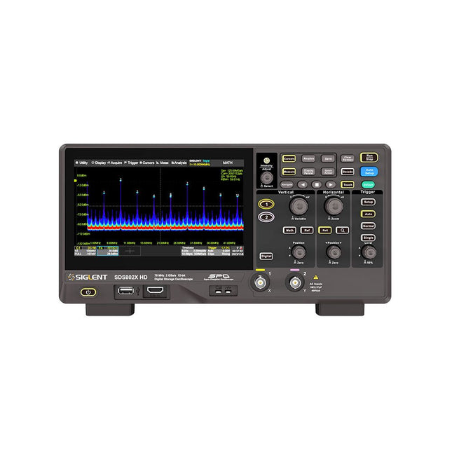
The Siglent SDS822X HD digital storage oscilloscope is based on 2 GSa/s, 12-bit Analog-Digital Converters and front ends with excellent noise floor performance. With a 200 MHz bandwidth, and a maximum record length of 100 Mpts, and the capability to analyze 2 analog channels alongside 16 digital channels, the SDS822X HD is perfectly suited for mixed signal analysis. Kenmerken 12-bit High Resolution 12-bit Analog-Digital Convertors with sample rate up to 2 GSa/s Front ends with 70 μVrms noise floor @ 200 MHz bandwidth 2/4 analog channels, up to 700 MHz bandwidth SPO technology Waveform capture rate up to 120,000 wfm/s (normal mode), and 500,000 wfm/s (sequence mode) Supports 256-level intensity grading and color temperature display modes. Up to 50 Mpts record length Digital trigger system Intelligent trigger: Edge, Slope, Pulse width, Window, Runt, Interval, Dropout, Pattern, Video (HDTV supported), Qualified, Nth edge, Delay, Setup/Hold time. Serial bus triggering and decoder, supports protocols I²C, SPI, UART, CAN, LIN. Segmented acquisition (Sequence) mode, dividing the maximum record length into multiple segments (up to 80,000), according to trigger conditions set by the user, with a very small dead time between segments to capture the qualifying event. History waveform record (History) function, the maximum recorded waveform length is 80,000 frames. Automatic measurements on 50+ parameters, supports statistics with histogram, track, trend, Gating measurement, and measurements on Math, History and Ref. 4 Math traces (2 Mpts FFT, addition, subtraction, multiplication, division, integration, differential, square root, etc.), supports formula editor. Abundant data analysis functions such as Search, Navigate, Counter, Bode plot and Power Analysis High Speed hardware-based Mask Test function, with Mask Editor tool for creating user-defined masks 16 digital channels (optional) 25 MHz waveform generator (optional) 7" TFT-LCD display with 1024 x 600 resolution; Capacitive touch screen supports multi-touch gestures. Interfaces include: USB Hosts, USB Device (USBTMC), LAN (VXI-11/Telnet/Socket), Pass/Fail, Trigger Out Built-in web server supports remote control over the LAN port using a web browser. Supports SCPI remote control commands. Supports external mouse and keyboard. Supports NTP. Specificaties Analog Channels 2 Bandwidth 200 MHz Vertical resolution 12-bit Sample rate (Max.) One channel mode: 100 Mpts/chTwo channel mode: Mpts/chFour channel mode: 25 Mpts/ch Memory depth (Max.) One channel mode: 50 Mpts/chTwo channel mode: 25 Mpts/ch Waveform capture rate (Max.) Normal mode: 120,000 wfm/sSequence mode: 500,000 wfm/s Trigger type Edge, Slope, Pulse width, Window, Runt, Interval, Dropout, Pattern, Video, Qualified, Nth edge, Delay, Setup/Hold time, Serial Serial trigger and decode (Standard) I²C, SPI, UART, CAN, LIN Measurement 50+ parameters, statistics, histogram, trend, and track supported Math 4 traces 2 Mpts FFT, Filter, +, -, x, ÷, ∫dt, d/dt, √, Identity, Negation, Absolute, Sign, ex, 10x, ln, lg, Interpolation, MaxHold, MinHold, ERES, Average. Supports formula editor Data analysis Search, Navigate, History, Mask Test, Counter, Bode plot, and Power Analysis Digital channel (optional) 16-channel; maximum sample rate up to 1 GSa/s; record length up to 10 Mpts USB AWG module (option) One channel, 25 MHz, sample rate of 125 MHz, wave length of 16 kpts, isolated output I/O 2x USB 2.0 Host, USB 2.0 Device, 10/100 M LAN, Auxiliary output (TRIG OUT, PASS/FAIL), SBUS (Siglent MSO) Probe (Standard) Passive probe PB470 for each channel Display 7 TFT-LCD with capacitive touch screen (1024x600) Inbegrepen 1x Siglent SDS822X Oscilloscope 2x Passive probe (200 MHz) PP520 1x Power cord (EU) 1x USB cable 1x Certificate of calibration 1x Quick start Downloads Datasheet Manual Programming guide
€ 635,25
-

SunFounder Universal Maker Sensor Kit (voor Raspberry Pi, Pico W, Arduino, ESP32)
Ontdek eindeloze creativiteit met de Universal Maker Sensor Kit, ontworpen voor gebruik met Raspberry Pi, Pico W, Arduino en ESP32. Deze veelzijdige kit biedt compatibiliteit met populaire ontwikkelingsplatforms, waaronder Arduino Uno R4 Minima/WiFi, Uno R3, Mega 2560, Raspberry Pi 5, 4, 3B+, 3B, Zero, Pico W en ESP32. Met meer dan 35 sensoren, actuatoren en displays is het perfect voor projecten variërend van omgevingsmonitoring en slimme huisautomatisering tot robotica en interactief gamen. Stapsgewijze tutorials in C/C++, Python en MicroPython begeleiden zowel beginners als ervaren makers door 169 spannende projecten. Kenmerken Brede compatibiliteit: Ondersteunt volledig Arduino (Uno R3, Uno R4 Minima/WiFi, Mega 2560), Raspberry Pi (5, 4, 3B+, 3B, Zero, Pico W) en ESP32, wat uitgebreide flexibiliteit op verschillende ontwikkelingsplatforms mogelijk maakt. Bevat instructies voor het bouwen van 169 projecten. Uitgebreide componenten: Bevat meer dan 35 sensoren, actuatoren en displaymodules die geschikt zijn voor uiteenlopende projecten zoals omgevingsbewaking, slimme huisautomatisering, robotica en interactieve gamecontrollers. Gedetailleerde tutorials: Biedt duidelijke, stapsgewijze tutorials over Arduino, Raspberry Pi, Pico W, ESP32 en elk inbegrepen component. Tutorials zijn beschikbaar in C/C++, Python en MicroPython, en zijn effectief afgestemd op zowel beginners als ervaren makers. Geschikt voor alle vaardigheidsniveaus: Biedt gestructureerde projecten die zijn ontworpen om gebruikers naadloos te begeleiden van beginners tot gevorderden in elektronica en programmeren, wat de creativiteit en technische expertise vergroot. Inbegrepen Breadboard Knopmodule Capacitieve bodemvochtigheidsmodule Vlamsensormodule Gas-/rooksensormodule (MQ2) Gyroscoop & Accelerometermodule (MPU6050) Hall-sensormodule Infraroodsnelheidssensormodule IR-obstakelvermijdingssensormodule Joystickmodule PCF8591 ADC DAC-convertermodule Fotoweerstandsmodule PIR-bewegingsmodule (HC-SR501) Potentiometermodule Pulsoximeter- en hartslagsensormodule (MAX30102) Regendruppeldetectiemodule Realtimeklokmodule (DS1302) Rotary Encoder-module Temperatuursensormodule (DS18B20) Temperatuur- en vochtigheidssensormodule (DHT11) Temperatuur, vochtigheid en Druksensor (BMP280) Time of Flight Micro-LIDAR afstandssensor (VL53L0X) Touch Sensor Module Ultrasone sensormodule (HC-SR04) Trillingssensormodule (SW-420) Waterniveausensormodule I²C LCD 1602 OLED-displaymodule (SSD1306) RGB LED-module Verkeerslichtmodule 5 V relaismodule Centrifugaalpomp L9110 motordrivermodule Passieve zoemermodule Servomotor (SG90) TT Motor ESP8266-module JDY-31 Bluetooth-module Voedingsmodule Documentatie Online Tutorial
€ 69,95
Leden: € 62,96
-
Siglent Siglent SPD4121X 4-kanaals Voeding (285 W)
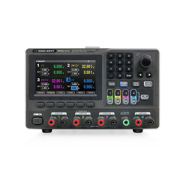
The Siglent SPD4121X is a 4-channel DC Linear Programmable Power Supply equipped with a 4.3-inch TFT-LCD display, friendly human-machine interface, and excellent performance indicators. Real-time waveform display provides engineers with an informative user interface. SPD4121X offers a total output power of 285 W with a resolution of 1 mV/1 mA. The maximum voltage and current for each channel are as follows: CH1: 15 V/1.5 A CH2: 12 V/10 A CH3: 12 V/10 A CH4: 15 V/1.5 A Kenmerken Rated output power: 285 W Rated voltage: 32 V, 12 V, 30 V Up to four high-precision power supplies with independent controllable outputs, supporting CH2 and CH3 series and parallel connections Clear graphical interface with waveform and timer display modes 5-digit voltage and current display with minimum resolution of 1 mV, 1 mA Fast output response time: <50us The high current channel support remote voltage compensation sense function. The maximum compensation voltage is 0.6 V Overvoltage protection and overcurrent protection or safe and accurate operation Equipped with a 4.3-inch TFT-LCD display (480 x 272 resolution) USB and LAN standard communication USB-GPIB module is optional Excellent channel density with up to 4 channels in a 3U half rack package Internal data storage for setups and parameters Embedded Web Server with instrument communication that doesn’t require software installation Fully SCPI programming command set support as well as a LabView driver for remote control and system automation Specificaties SPD4323X SPD4121X SPD4306X Channel Output CH1: Voltage 0 to 6 V Current 0 to 3.2 ACH2: Voltage 0 to 32 V Current 0 to 3.2 ACH3: Voltage 0 to 32 V Current 0 to 3.2 ACH4: Voltage 0 to 6 V Current 0 to 3.2 A CH1: Voltage 0 to 15 V Current 0 to 1.5 ACH2: Voltage 0 to 12 V Current 0 to 10 ACH3: Voltage 0 to 12 V Current 0 to 10 ACH4: Voltage 0 to 15 V Current 0 to 1.5 A CH1: Voltage 0 to 15 V Current 0 to 1.5 ACH2: Voltage 0 to 30 V Current 0 to 6 ACH3: Voltage 0 to 30 V Current 0 to 6 ACH4: Voltage 0 to 15 V Current 0 to 1 A Resolution 1 mV, 1 mA 1 mV, 1 mA 1 mV, 1 mA Setting Accuracy Voltage: ±(0.03% of reading+10) mV, Current: ±(0.3% of reading+10) mA Voltage: ±(0.03% of reading+10) mV, Current: ±(0.3% of reading+10) mA Voltage: ±(0.03% of reading+10) mV, Current: ±(0.3% of reading+10) mA Readback Accuracy Voltage: ±(0.03% of reading+10) mV, Current: ±(0.3% of reading+10) mA Voltage: ±(0.03% of reading+10) mV, Current: ±(0.3% of reading+10) mA Voltage: ±(0.03% of reading+10) mV, Current: ±(0.3% of reading+10) mA Display 4.3" TFT-LCD 5-digit voltage and current display 4.3" TFT-LCD 5-digit voltage and current display 4.3" TFT-LCD 5-digit voltage and current display Output power 240 W 285 W 400 W Inbegrepen 1x Siglent SPD4121X Power Supply 1x Power cord (EU) 1x Output test cord (3 A) 1x USB cable 1x Quick start guide Downloads Datasheet Manual Quick start
€ 871,20


