Le chargeur intégré est disponible pour nos clients OR et VERT sur le site d'Elektor Magazine !
Pas encore membre ? Cliquez ici .
Raspberry Pi Pico comme analyseur de spectre des FFT avec du matériel bon marché
régulateur de tension linéaire ±40 V une alimentation de qualité pour l'amplification du Fortissimo-100... et d'autres !
la communication sans fil des microcontrôleurs devient flexible l'EEPROM du point de vue de la mise en réseau pour les microcontrôleurs sans fil
5000 ? à gagner! participez au concours de conception d'innovation sans fil STM32
2023 : l'odyssée de l'IA en savoir plus sur le code ChatGPT
LoRa, un couteau suisse (1) le protocole LoRa et ses avantages
du courant réglable avec générateur de montre intégré testez vos alimentations, convertisseurs de tension et batteries
les nouvelles cartes Arduino UNO R4 Minima et WiFi
des potentiomètres logarithmiques qui sont exponentielles !
Carte d'interface pour pilote de moteur Un BoB pour un pilote continu de 5 A avec une taille de 3×3 mm
sur le vif danger de l'électronique
une architecture cellulaire de plus d'une consommation pour l'Internet des objets (IdO) ? Caractéristiques des technologies LTE-M et NB-IoT pour le développement de la basse consommation (LPWAN)
communication sans utilisation de systèmes et d'aides IoT dans les modules Arduino MKR normes de communication pour les modules Arduino pour l'IoT
pertes en courant alternatif dan les composants magnétiques évitez la surchauffe des inductances !
optimiser son déploiement cloud grâce aux équipements de mesure
mise en œuvre de Matter : à quoi sert le déploiement des équipements de Matter ?
le YARD Stick One en utilisant la méthode de test pour les fréquences de 1 GHz
relais à verrouillage drôle de composant, la série
PIC O?Horloge ? prendre le pouls du temps conception d'un récepteur de signaux horaires SDR
Directive sur le devoir de diligence Le statu quo ne suffira pas
démarrer en électronique ?amplificateur de tension
activateur d'infrasons avec l'Arduino Pro Mini un projet extrait du livre 'Arduino & Co.' d'Elektor
compteur d'énergie base sur le cloud avec un module ESP32 et un capteur tension/courant PZEM-004T
guide de programmation Bare-Metal (2) timer précis, UART et débogage
Hexadoku
De OWON SDS1102 is een betaalbare benchtop digitale oscilloscoop die solide prestaties combineert met essentiële meetfuncties. Deze 2-kanaals oscilloscoop biedt een bandbreedte van 100 MHz, een sample rate van 1 GS/s, een 7-inch LCD-display en een geheugendiepte van 10 kpts. Daarmee is het een praktische keuze voor dagelijkse elektronicatests, foutopsporing en onderwijs.
De SDS1102 beschikt over een vereenvoudigd triggersysteem met niveau- en flanktriggering, waardoor gangbare signalen eenvoudig kunnen worden vastgelegd en geanalyseerd. Het apparaat is ontworpen voor toepassingen waarvoor geen grote geheugendiepte of geavanceerde triggerfuncties nodig zijn, en biedt een eenvoudige en kostenefficiënte oplossing voor basis-signaalanalyse.
Kenmerken
Bandbreedte: 100 MHz
2 kanalen
Bemonsteringssnelheid: 1 GS/s
Ultradunne behuizing
7-inch lcd met hoge resolutie
Ondersteuning voor SCPI en LabVIEW
Specificaties
Bandbreedte
100 MHz
Horizontale schaal (s/div)
5 ns/div - 1000 s/div
Kanalen
2
Verticale gevoeligheid
5 mV/div - 5 V/div (bij ingang)
DC Gain nauwkeurigheid
3%
Verticale resolutie (A/D)
8 bits (2 kanalen tegelijk)
Ingang
Ingangsimpedantie
1 MΩ, 10 pF
Ingangskoppeling
AC, DC, GND
Max ingangsspanning
± 400 V, CATI, CATII
Passieve probes
x1; 10
Probe verzwakkingsfactor
x1; x10; x100; x1000
Triggersysteem
Trigger mode
Auto, Normal, Single
Trigger type
Flank, Video
Flank triggerbron
CH1, CH2
Video trigger
Sampletype
Real-time
Samplefrequentie
1 GS/s
Equivalente samplesnelheid
No
Golflengte
10K pts
Interpolatie
sin(x)/x
Meet- en rekenkundig bewerkingssysteem
Automatische meting
Vpp, Vavg, RMS, Frequency, Period, Vmax, Vmin, Vtop, Vbase, Width, Overshoot, Pre-shoot Rise time, Fall time, +Width, -Width, +Duty, -Duty, Delay A->B, Delay A->B, area, cycle area
Rekenkundige functies
Addition, Subtraction, Multiplication, Division, FFT
Algemene kenmerken
Display maat
7" color LCD
Display resolutie
800 x 480
Voeding
100-240 V, 45-440 Hz, <15 W
Afmetingen
301 x 70 x 152 mm
Gewicht
1,1 kg
Inbegrepen
1x OWON SDS1102 Oscilloscoop
2x Oscilloscoopsonde
1x Sonde aanpassen
1x Netsnoer
1x USB-kabel
1x CD-Rom
1x Snelstartgids
Downloads
Quick Guide
Manual
PC Software
SCPI Commands
Elektor GREEN and GOLD members can download their digital edition here.
Not a member yet? Click here.
Cloc 2.0The Alarm Clock You've Always Wanted
RP2040 PIO in PracticeExperiments Using the RP2040’s Programmable I/O
Poor Man's ChipTweakerWe Have (Low-Budget) Ways of Making You Talk
USB True Random Number GeneratorTwo PICs for the Price of One AVR
Pimp My MicSelf-Designed Level Booster
FFT with a MaixduinoFrequency spectrum display
From Life’s ExperienceDesign Logic (or Non-Logic)
UCN5804 Stepper Motor DriverPeculiar Parts, the Series
Circuit Simulation With Micro-CapFirst Steps in a Complicated World
PAUL Award 2022Young Technical Talents and Their Creative Solutions
My First Software-Defined RadioBuilt in Less Than 15 Minutes
Microcontroller Documentation Explained (Part 1)Datasheet structure
What’s Next for AI and Embedded Systems?Tools, Platforms, and Writer Replacements
Digitizing Vertical Farming
Infographics: Embedded and AI Today and Tomorrow
An Introduction to TinyML
JetCarrier96A Versatile NVIDIA Jetson Development System
Case Study: Taking EV Charging Global with a Universal RFID Solution
High-Performance in Every ClassComputer-on-Module Standards
Starting Out in ElectronicsLet’s Get Active!
I²C Communication Using Node.js and a Raspberry PiSee Your Sensor Data in a Browser
Video Output with Microcontrollers (2)VGA and DVI Output
The Metronom Real-Time Operating SystemAn RTOS for AVR Processors
DVI on the RP2040An Interview with Luke Wren, Chip Developer at Raspberry Pi
Display HAT MiniShow the Weather Forecast on Raspberry Pi!
WEEF 2022 Awards: Celebrate the Good
Hexadoku
Programming and Projects for the Minima and WiFi
Based on the low-cost 8-bit ATmega328P processor, the Arduino Uno R3 board is likely to score as the most popular Arduino family member, and this workhorse has been with us for many years. Eleven years later, the long-overdue successor, the Arduino Uno R4, was released. It is built around a 48 MHz, 32-bit Arm Cortex-M4 microcontroller and provides significantly expanded SRAM and Flash memory. Additionally, a higher-precision ADC and a new DAC are added to the design. The Uno R4 board also supports the CAN Bus with an interface.
Two versions of the board are available: Uno R4 Minima, and Uno R4 WiFi. This book is about using these new boards to develop many different and interesting projects with just a handful of parts and external modules. All projects described in the book have been fully tested on the Uno R4 Minima or the Uno R4 WiFi board, as appropriate.
The project topics include the reading, control, and driving of many components and modules in the kit as well as on the relevant Uno R4 board, including
LEDs
7-segment displays (using timer interrupts)
LCDs
Sensors
RFID Reader
4x4 Keypad
Real-time clock (RTC)
Joystick
8×8 LED matrix
Motors
DAC (Digital-to-analog converter)
LED matrix
WiFi connectivity
Serial UART
CAN bus
Infrared controller and receiver
Simulators
… all in creative and educational ways with the project operation and associated software explained in great detail.
Highlights
Output Frequency (Sine): 100 MHz
Output Frequency (Square): 25 MHz
Channels: 2
Arbitrary Waveform Length: 16 Mpts
Kenmerken
Unique SiFi II (Signal Fidelity II) technology: generate the arbitrary waveforms point by point; recover the signal without distortion; sample rate accurate and adjustable; jitter of all the output waveforms (including Sine, Pulse, etc.) as low as 200 ps
16 Mpts memory depth per channel for arbitrary waveforms
Standard dual-channel with the same performance, equivalent to two independent signal sources
High frequency stability: ±1 ppm; low phase noise: -105 dBc/Hz
Built-in high-order harmonic generator (at most 8-order harmonics)
Built-in 7 digits/s, 240 MHz bandwidth full featured frequency counter
Up to 160 built-in arbitrary waveforms, covering the common signals in engineering application, medical electronics, auto electronics, math processing, and other various fields
Sample rate up to 250 MSa/s, vertical resolution 16 bits
Arbitrary waveform sequence editing function available; arbitrary waveforms also can be generated through the PC software
Various analog and digital modulation functions: AM, FM, PM, ASK, FSK, PSK, and PWM.
Standard waveform combine function, capable of outputting specified waveforms combined with the basic waveforms
Standard channel tracking function, when enabled, all the parameters of both channels are updated based on users' configurations
Standard interface: USB Host&Device and LAN (LXI Core 2011 Device); USB-GPIB function supported
4.3'' TFT
Inbegrepen
1x Rigol DG2102 Function/Arbitrary Waveform Generator
1x Power cord
1x USB cable
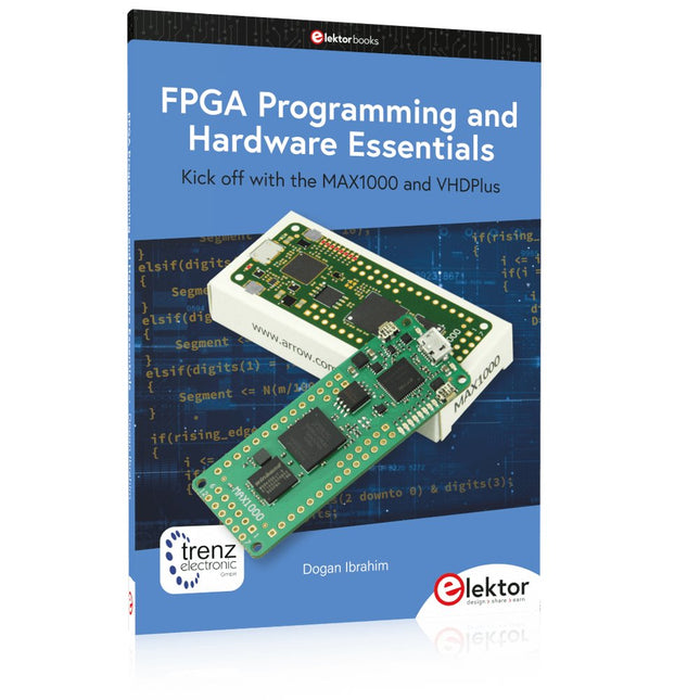
Kick off with the MAX1000 and VHDPlus
Ready to Master FPGA Programming? In this guide, we’re diving into the world of Field Programmable Gate Arrays (FPGAs) – a configurable integrated circuit that can be programmed after manufacturing. Imagine bringing your ideas to life, from simple projects to complete microcontroller systems!
Meet the MAX1000: a compact and budget-friendly FPGA development board packed with features like memory, user LEDs, push-buttons, and flexible I/O ports. It’s the ideal starting point for anyone wanting to learn about FPGAs and Hardware Description Languages (HDLs).
In this book, you’ll get hands-on with the VHDPlus programming language – a simpler version of VHDL. We’ll work on practical projects using the MAX1000, helping you gain the skills and confidence to unleash your creativity.
Get ready for an exciting journey! You’ll explore a variety of projects that highlight the true power of FPGAs. Let’s turn your ideas into reality and embark on your FPGA adventure – your journey starts now!
Exciting Projects You’ll Find in This Book
Arduino-Driven BCD to 7-Segment Display Decoder
Use an Arduino Uno R4 to supply BCD data to the decoder, counting from 0 to 9 with a one-second delay
Multiplexed 4-Digit Event Counter
Create an event counter that displays the total count on a 4-digit display, incrementing with each button press
PWM Waveform with Fixed Duty Cycle
Generate a PWM waveform at 1 kHz with a fixed duty cycle of 50%
Ultrasonic Distance Measurement
Measure distances using an ultrasonic sensor, displaying the results on a 4-digit 7-segment LED
Electronic Lock
Build a simple electronic lock using combinational logic gates with push buttons and an LED output
Temperature Sensor
Monitor ambient temperature with a TMP36 sensor and display the readings on a 7-segment LED
Downloads
Software
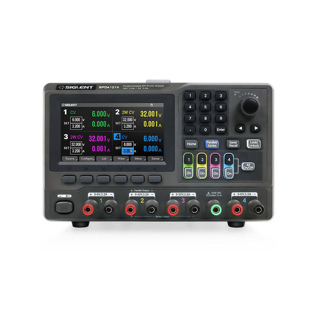
The Siglent SPD4121X is a 4-channel DC Linear Programmable Power Supply equipped with a 4.3-inch TFT-LCD display, friendly human-machine interface, and excellent performance indicators. Real-time waveform display provides engineers with an informative user interface.
SPD4121X offers a total output power of 285 W with a resolution of 1 mV/1 mA. The maximum voltage and current for each channel are as follows:
CH1: 15 V/1.5 A
CH2: 12 V/10 A
CH3: 12 V/10 A
CH4: 15 V/1.5 A
Kenmerken
Rated output power: 285 W
Rated voltage: 32 V, 12 V, 30 V
Up to four high-precision power supplies with independent controllable outputs, supporting CH2 and CH3 series and parallel connections
Clear graphical interface with waveform and timer display modes
5-digit voltage and current display with minimum resolution of 1 mV, 1 mA
Fast output response time: <50us
The high current channel support remote voltage compensation sense function. The maximum compensation voltage is 0.6 V
Overvoltage protection and overcurrent protection or safe and accurate operation
Equipped with a 4.3-inch TFT-LCD display (480 x 272 resolution)
USB and LAN standard communication
USB-GPIB module is optional
Excellent channel density with up to 4 channels in a 3U half rack package
Internal data storage for setups and parameters
Embedded Web Server with instrument communication that doesn’t require software installation
Fully SCPI programming command set support as well as a LabView driver for remote control and system automation
Specificaties
SPD4323X
SPD4121X
SPD4306X
Channel Output
CH1: Voltage 0 to 6 V Current 0 to 3.2 ACH2: Voltage 0 to 32 V Current 0 to 3.2 ACH3: Voltage 0 to 32 V Current 0 to 3.2 ACH4: Voltage 0 to 6 V Current 0 to 3.2 A
CH1: Voltage 0 to 15 V Current 0 to 1.5 ACH2: Voltage 0 to 12 V Current 0 to 10 ACH3: Voltage 0 to 12 V Current 0 to 10 ACH4: Voltage 0 to 15 V Current 0 to 1.5 A
CH1: Voltage 0 to 15 V Current 0 to 1.5 ACH2: Voltage 0 to 30 V Current 0 to 6 ACH3: Voltage 0 to 30 V Current 0 to 6 ACH4: Voltage 0 to 15 V Current 0 to 1 A
Resolution
1 mV, 1 mA
1 mV, 1 mA
1 mV, 1 mA
Setting Accuracy
Voltage: ±(0.03% of reading+10) mV, Current: ±(0.3% of reading+10) mA
Voltage: ±(0.03% of reading+10) mV, Current: ±(0.3% of reading+10) mA
Voltage: ±(0.03% of reading+10) mV, Current: ±(0.3% of reading+10) mA
Readback Accuracy
Voltage: ±(0.03% of reading+10) mV, Current: ±(0.3% of reading+10) mA
Voltage: ±(0.03% of reading+10) mV, Current: ±(0.3% of reading+10) mA
Voltage: ±(0.03% of reading+10) mV, Current: ±(0.3% of reading+10) mA
Display
4.3" TFT-LCD 5-digit voltage and current display
4.3" TFT-LCD 5-digit voltage and current display
4.3" TFT-LCD 5-digit voltage and current display
Output power
240 W
285 W
400 W
Inbegrepen
1x Siglent SPD4121X Power Supply
1x Power cord (EU)
1x Output test cord (3 A)
1x USB cable
1x Quick start guide
Downloads
Datasheet
Manual
Quick start
Raspberry Pi 5 provides two four-lane MIPI connectors, each of which can support either a camera or a display. These connectors use the same 22-way, 0.5 mm-pitch “mini” FPC format as the Compute Module Development Kit, and require adapter cables to connect to the 15-way, 1 mm-pitch “standard” format connectors on current Raspbery Pi camera and display products.These mini-to-standard adapter cables for cameras and displays (note that a camera cable should not be used with a display, and vice versa) are available in 200 mm, 300 mm and 500 mm lengths.
Deze bundel gaat helemaal over het ontwerpen van projecten gebaseerd op de 555 timer IC. Het boek bevat meer dan 45 volledig geteste en gedocumenteerde projecten. Samen met de kit, die meer dan 130 through-hole componenten bevat, kunt u alle beschreven projecten bouwen op een breadboard. De opzet maakt het ook gemakkelijk om de projecten aan te passen en ermee te experimenteren.
Meer dan 45 builds voor de legendarische 555 Chip (en de 556, 558)
Enkele van de projecten in het boek zijn:
Afwisselend knipperende twee LED's
De knippersnelheid van de LED's wijzigen
Aan/uit-schakelaar van de aanraaksensor
In-/uitschakelvertraging
Lichtafhankelijk geluid
Donker/lichtschakelaar
Tone Burst-generator
Timer voor lange duur
LED's achtervolgen
LED-roulettespel
Verkeerslichten
Continuïteitstester
Elektronisch slot
Schakel over naar debouncen van contacten
Elektronisch speelgoedorgel
Alarmsysteem met meerdere sensoren
Metronoom
Spanningsvermenigvuldigers
Elektronische dobbelstenen
Weergaveteller met 7 segmenten
Motorbesturing
Dobbelstenen met 7 segmenten
Elektronische sirene
Diverse andere projecten
Kit-inhoud
Weerstanden
1x 15 kΩ
1x 68 kΩ
2x 47 kΩ
1x 82 kΩ
2x 820 Ω
1x 8,2 kΩ
3x 10 kΩ
1x 1,8 kΩ
1x 6,8 kΩ
14x 2,2 kΩ
10x 680 Ω
1x 27 kΩ
1x 5,6 kΩ
1x 560 kΩ
1x 4,7 kΩ
1x 3,3 kΩ
3x 33 kΩ
1x 36 kΩ
2x 100 kΩ
5x 1 kΩ
1x 3,9 kΩ
2x 56 kΩ
2x 12 kΩ
1x 10 kΩ potentiometer
1x 1 MΩ potentiometer
2x 50 kΩ potentiometer
3x 20 kΩ potentiometer
1x 10 kΩ potentiometer
1x 10 kΩ potentiometer
1x 50 kΩ potentiometer
1x 100 kΩ potentiometer
1x 50 kΩ potentiometer
Condensatoren
1x 0,33 μF
1x 1 μF
1x 10 nF
1x 22 nF
1x 47 nF
1x 100 nF
1x 10 μF elektrolytisch
1x 33 μF elektrolytisch
2x 100 μF elektrolytisch
LED's
10x 5 mm rode LED
10x 3 mm rode LED
3x 3 mm gele LED
3x 3 mm groene LED
1x 7-segment-LED met gemeenschappelijke kathode
Semiconductors
3x 555 timer
1x CD4017 counter
1x CD4026 counter
1x CD4011 NAND-poort
4x 1N4148-diode
1x IRFZ46N MOSFET
1x Thermistor
1x Lichtafhankelijke weerstand (LDR)
Diverse
1x Passieve buzzer
1x Actieve buzzer
1x SG90 servo
1x 8 Ω miniluidspreker
1x 9 V DC borstelmotor
1x 5 V relais
1x 9 V batterijclip
7x Drukknopschakelaars
1x Broodplank
1x Breadboard-jumperdraden
Onderzoek je schakelingen met hoge precisie en soldeer zelfs de kleinste SMD's en onderdelen zonder problemen.
Features
De multifunctionele HDMI Digitale Microscoop heeft Full HD, comfortabele beeldschermruimte, een verbeterde ergonomie, meerdere uitgangssignalen met verschillende resoluties.
De kantelhoek van de brede LCD monitor is instelbaar.
Wordt geleverd met afstandsbediening.
Kan als zelfstandig apparaat worden gebruikt.
Specificaties
Beeldscherm
7 inch (17,8 cm)
Beeldsensor
4 MP
Video output
UHD 2880x2160 (24fps)FHD 1920x1080 (60fps/30fps)HD 1280x720 (120fps)
Video formaat
MP4
Vergrotingsfactor
Tot 270 keer (27 inch HDMI monitor)
Foto resolutie
Max. 12 MP (4032x3024)
Foto formaat
JPG
Focus bereik
Min. 5 cm
Frame snelheid
Max. 120 fps (onder 600 Lux helderheid & HDP120)
Video interface
HDMI
Opslag
microSD card (tot 32 GB)
Voeding
5 V DC
Lichtbron
2 LED's met standaard
Afmetingen
20 x 12 x 19 cm
Inbegrepen
1x Andonstar AD407 Digitale Microscoop
1x Metalen statief met 2 LED's
1x Optische beugel
1x UV-filter
1x IR afstandsbediening
1x Verloopkabel
1x Voedingsadapter
1x HDMI kabel
2x Schroeven
1x Schroevendraaier
1x Gebruiksaanwijzing
Downloads
Manual
Model vergelijking
AD407
AD407 Pro
AD409
AD409 Pro-ES
Screen size
7 inch (17,8 cm)
7 inch (17,8 cm)
10,1 inch (25,7 cm)
10,1 inch (25,7 cm)
Image sensor
4 MP
4 MP
4 MP
4 MP
Video output
2160p
2160p
2160p
2160p
Interfaces
HDMI
HDMI
USB, HDMI, WiFi
USB, HDMI, WiFi
Video format
MP4
MP4
MP4
MP4
Magnification
Up to 270x
Up to 270x
Up to 300x
Up to 300x
Photo resolution
Max. 4032x3024
Max. 4032x3024
Max. 4032x3024
Max. 4032x3024
Photo format
JPG
JPG
JPG
JPG
Focus distance
Min. 5 cm
Min. 5 cm
Min. 5 cm
Min. 5 cm
Frame rate
Max. 120f/s
Max. 120f/s
Max. 120f/s
Max. 120f/s
Storage
microSD card
microSD card
microSD card
microSD card
PC support
No
No
Windows
Windows
Mobile connection
No
No
WiFi + Measurement
WiFi + Measurement
Power source
5 V DC
5 V DC
5 V DC
5 V DC
Light source
2 LEDs with the stand
2 LEDs with the stand
2 LEDs with the stand
2 LEDs with the stand
Endoscope
No
No
No
Yes
Stand size
20 x 12 x 19 cm
20 x 18 x 32 cm
18 x 20 x 30 cm
18 x 20 x 32 cm
Weight
1,6 kg
2,1 kg
2,2 kg
2,5 kg
De Elektor Super Servo Tester kan servo's aansturen en servosignalen meten. Hij kan tot vier servokanalen tegelijkertijd testen.
De Super Servo Tester wordt geleverd als bouwpakket. Alle onderdelen die nodig zijn om de Super Servo Tester in elkaar te zetten zijn inbegrepen in de set. Het bouwen van de kit vereist enige basisvaardigheid met solderen. De microcontroller is al geprogrammeerd.
De Super Servo Tester beschikt over twee bedrijfsmodi: Control/Manual en Measure/Inputs.
In de modus Control/Manual genereert de Super Servo Tester besturingssignalen op zijn uitgangen voor maximaal vier servo's, of voor de flight controller of ESC. De signalen worden ingeregeld door de vier potentiometers.
In de modus Measure/Inputs meet de Super Servo Tester de servosignalen die op de ingangen zijn aangesloten. Deze signalen kunnen afkomstig zijn van bijvoorbeeld een ESC, een flight controller, of de ontvanger, of een ander apparaat. De signalen worden ook naar de uitgangen geleid om de servo's of de flight controller of ESC aan te sturen. De resultaten worden op het display weergegeven.
Specificaties
Operating modi
Control/Manual & Measure/Inputs
Kanalen
3
Servosignaal ingangen
4
Servosignaal uitgangen
4
Alarm
Zoemer & LED
Weergave
0,96" OLED (128 x 32 pixels)
Ingangsspanning op K5
7 - 12 VDC
Ingangsspanning op K1
5 - 7,5 VDC
Ingangsstroom
30 mA (9 VDC op K5, en niets aangesloten op K1 en K2)
Afmetingen
113 x 66 x 25 mm
Gewicht
60 g
Inbegrepen
Weerstanden (0,25 W)
R1, R3
1 k?, 5%
R2, R4, R5, R6, R7, R9, R10
10 k?, 5%
R8
22 ?, 5%
P1, P2, P3, P4
10 k?, lin/B, verticale potentiometer
Condensatoren
C1
100 ?F 16 V
C2
10 ?F 25 V
C3, C4, C7
100 nF
C5, C6
22 pF
Halfgeleiders
D1
1N5817
D2
LM385Z-2.5
D3
BZX79-C5V1
IC1
7805
IC2
ATmega328P-PU, geprogrammeerd
LED1
LED, 3 mm, rood
T1
2N7000
Diversen
BUZ1
Piëzo-zoemer met oscillator
K1, K2
2-rijige, 12-voudige pinheader, 90°
K5
Barrel jack
K4
1-rijige, 4-polige pinvoet
K3
2-rijige, 6-voudige boxed pinheader
S1
Schuifschakelaar DPDT
S2
Schuifschakelaar SPDT
X1
Kristal, 16 MHz
28-voudige DIP-voet voor IC2
Elektor printplaat
OLED-scherm, 0,96", 128 x 32 pixels, 4-pins I²C-interface
Links
Elektor Magazine
Elektor Labs
Deze complete microcontroller-programmeercursus op basis van de Arduino Uno bevat een leerboek, een componentenkit, praktische projecten en een uitgebreide online cursus met simulaties. Ideaal om embedded systems stap voor stap te leren programmeren met Arduino via een praktische hands-on aanpak.
Een praktische introductie tot embedded systems met de Arduino Uno
Deze cursus is ontworpen voor beginners in embedded systems die op zoek zijn naar een gestructureerde en voorbeeldgerichte start.
Een kit met LED’s en weerstanden, schakelaars, sensoren en actuatoren, displays, een breadboard en draden is inbegrepen. Deze worden in de cursus gebruikt om voorbeeldtoepassingen te demonstreren.
Er is geen voorkennis van Arduino of embedded ontwikkeling vereist. Elke sectie bevat praktische voorbeelden en mini-projecten om belangrijke concepten te versterken en verdere verkenning te stimuleren. Aan het einde van de cursus kunt u niet alleen de voorbeelden reproduceren, maar ook uitbreiden met uw eigen ideeën en toepassingen.
Wat leert u?
Microcontrollerprogrammering met Arduino met behulp van het Uno R3 board
Werken met digitale I/O, knoppen en encoders uitlezen, LED’s en relais aansturen
Analoge ingangen, spanningen en sensoren uitlezen
Genereren van analoge uitgangssignalen en PWM
Gebruik van seriële communicatie zoals UART, I²C en SPI om displays aan te sturen en digitale sensoren en SD-kaarten uit te lezen
Tijdbeheer
Werken met interrupts
Realtime sensorinput en besturing via knoppen, LED’s en displays
Aansturen van actuatoren zoals relais en servomotoren
Voor wie is dit?
Studenten en zelflerenden die embedded systems willen ontdekken
Makers en IoT-enthousiastelingen die hun hardwarevaardigheden willen verbeteren
Docenten en trainers die kant-en-klaar lesmateriaal zoeken
Wat zit er in de doos?
Toegang tot de volledige cursus op het Elektor Academy Pro leerplatform
Uno R3 microcontrollerboard + USB-kabel
Boek: Programming Microcontrollers in C/C++ Using Arduino
Downloadbare projectbestanden voor elke module
Componentenkit:
2× LED, rood, 5 mm
LED, groen, 5 mm
3× weerstand, 470 Ω, 0,25 W
LDR
Potentiometer, 10 kΩ, lineair
Drukknop
Rotary encoder module
Relaismodule
DHT22 temperatuur- en vochtigheidssensor
TM1637-compatibel 4-digit 7-segment display
MPU-6050 IMU met headers
SSD1306-compatibel I²C OLED display
Micro SD-kaartadapter met header
Buzzer
SG90 micro servo
ILI9341-compatibel SPI 240×320 TFT display
20× jumper wires
Breadboard
Alle programmeercursussen (en verschillen in inhoud)
Cursus
Arduino
Raspberry Pi Pico with Arduino C/C++
ESP32 with Arduino C/C++
Raspberry Pi Pico with MicroPython
ESP32 with MicroPython
Online cursus
Access to Arduino Course
Access to Pico with Arduino C/C++ Course
Access to ESP32 with Arduino C/C++ Course
Access to Pico with MicroPython Course
Access to ESP32 with MicroPython Course
Board
Uno R3
Raspberry Pi Pico
ESP32
Raspberry Pi Pico
ESP32
Boek
Programming Microcontrollers in C/C++ Using Arduino
Programming Microcontrollers in C/C++ Using Arduino
Programming Microcontrollers in C/C++ Using Arduino
Programming Microcontrollers in MicroPython
Programming Microcontrollers in MicroPython
Kit
40-delige componenten-kit
40-delige componenten-kit
40-delige componenten-kit
40-delige componenten-kit
40-delige componenten-kit