De Elektor Zenerdiode-tester is in wezen een constante-stroombron die in stappen van 1 tot 50 mA kan worden geschakeld. Hij kan worden gebruikt om zenerdiodes tot een maximum van 54 V te testen. Dankzij een 60-V step-upconverter kan het apparaat worden gevoed met de gebruikelijke 5 tot 12 V.
Het principe van deze tester is eenvoudig. Een zenerdiode of een ander DUT (device under test, zoals een LED) wordt gevoed door een instelbare stroombron. De spanning over het DUT kan met een multimeter worden gemeten. De spanning van de meeste (kleine) zenerdiodes wordt gespecificeerd bij een stroom van 5 mA. Afhankelijk van de toepassing kan ook de spanning bij andere stromen interessant zijn. Daarom zijn er zes stroominstellingen beschikbaar: 1, 2, 5, 10, 20 en 50 mA. LED’s worden vaak gespecificeerd bij een stroom van 20 mA.
Wat kan worden getest:
Of een zenerdiode defect is (kortsluiting of hoogohmig).
Of een zenerdiode de juiste zenerspanning heeft.
Hoe een zenerspanning verandert bij verschillende stromen.
Welke exacte spanning aanwezig is bij een geïntegreerde spanningsreferentie.
Of LED’s in een serieschakeling verschillen in helderheid (vandaar de stroom van 20 mA).
Wat de stroomversterking is bij verschillende basisstromen in (vermogens)transistoren.
De kit bevat alle onderdelen die in de stuklijst staan vermeld, inclusief printplaat en behuizing.
Specificaties
Voedingsspanning
5…12 V/2 A (USB-C)
Voedingsstroom (Itest = 50 mA)
1,1 A bij 5 V / 412 mA bij 12 V
Selecteerbare stromen
1, 2, 5, 10, 20 en 50 mA
Max. testspanning
>54 V bij Itest ≥1 mA
Max. uitgangsspanning
60 V bij Itest = 0 mA
Spanningslimiet bij 5 V
4,5 V bij Itest = 1 mA / 5,18 V bij Itest = 50 mA
Afmetingen (behuizing)
110 x 82 x 44 mm
Afmetingen (PCB)
105,4 x 67,3 mm
Aansluitingen
4 mm banaanstekkerbussen voor multimeter
2 mm banaanstekkerbussen voor testklemmen
USB-C-aansluiting voor voeding
Inbegrepen
Weerstanden
R1 = 3.3 kΩ, 600 mW, 1%
R2 = 0.15 Ω, 1 W, 5%, LS 12.7 mm, ø 3.5 mm
R3, R8 = 180 Ω, 600 mW, 1%
R4, R6, R16 = 1 kΩ, 600 mW, 1%
R5, R19 = 47 kΩ, 600 mW, 1%
R7 = 3.9 kΩ, 1 W, 5%, LS 12.7 mm, ø 3.5 mm
R9, R10, R12 = 10 kΩ, 600 mW, 1%
R11, R13 = 100 Ω, 600 mW 1%
R14 = 249 Ω, 600 mW, 1%
R15 = 499 Ω, 600 mW, 1%
R17 = 2.49 kΩ, 250 mW, 1%
R18 = 4.99 kΩ, 250 mW, 1%
Condensatoren
C1 = 470 uF / 35 V, 20%, Ir = 1.86 A, ø 12.5 mm, LS 5 mm, ESR = 0.038 Ω (Panasonic EEUTP1V471)
C2 = 1 uF / 100 V, 10%, X7R, LS 5 mm
C3 = 2.2 nF / 50 V, 10%, X7R, LS 5 mm
C4, C7 = 100 nF / 100 V, 10%, X7R, LS 5 mm
C5 = 100 uF / 100 V, 20%, ø 14 mm max., LS 5 mm
C6 = 1 nF / 100 V, 10%, X7R, LS 5 mm
Inductor
L1 = 100 uH, Irms = 2.4 A, Isat = 3.5 A, 0.09 Ω, radial, pitch 2.5/5/10 mm, ø 14 mm max. (Kemet SBC8-101-242)
Halfgeleiders
D1 = MUR120G, DO-41
D2, D4 = STPS3150RL, DO-201AD
D3 = Z-diode, 18 V, 1.3 W (BZX85C18)
D5 = Z-diode, 5.1 V, 0.5 W (1N5231B)
LED1 = LED in pushbutton S1
LED2 = LED, green, 3 mm
IC1 = MC34063, DIP-8
IC2 = LM4040BIZ-5.0/NOPB, TO-92 (TO-226AA-3)
IC3 = TL051CP, DIP-8
T1 = BC327.25, TO-92
T2 = STP40NF10L, TO-220
T3 = IRF9510PBF, TO-220
T4 = 2N7000, TO-92
Overige
K1, K2, S1, S3 = 2-way screw terminal block, LS 3.5 mm, max. 1.5 mm²
connected to K1 = USB-C socket, 30 V/3 A, chassis mounted, wired, 9 x 16 mm
connected to K2 = Banana Connector, 2 mm, Socket, 60 VDC, Panel Mount, red (Multicomp 24.102.1)
connected to K2 = Banana Connector, 2 mm, Socket, 60 VDC, Panel Mount, black (Multicomp 24.102.2)
Test clip, red, 30 VAC/60 VDC (Hirschmann 931467101)
Test clip, black, 30 VAC/60 VDC (Hirschmann 931467100)
S1 = Pushbutton, panel mount, SPST-NO, 30 DC/100 mA, with red LED
S2 = Rotary Switch, 6 position, 2 pole, 30°, 250 V/150 mA
S3 = Toggle switch, panel mount, SPDT, solder lugs, 28 VDC
T2, T3 = Heat sink, 15°C/W, FK 214 SA-CB
Enclosure Hammond 1591XXSSBK, ABS, 110 x 82 x 44 mm
Knob for S2, round shaft 6 mm, ø 21 mm, with indicator line (Multicomp CP-LB21-6-6D)
4 x Self-tapping screw #4-1/4", carbon steel, pan head
Banana plug, red, 2 mm, 60 VDC (Multicomp 25.205.1)
Banana plug, black, 2 mm, 60 VDC (Multicomp 25.205.2)
Banana socket, black 4 mm, panel mount
Banana socket, red 4 mm, panel mount
for LED1, LED2 = Pin header, 1 x 2, vertical, pitch 2.54 mm
for LED1, LED2 = Pin socket, 1 x 2, vertical, pitch 2.54 mm
for T2, T3 = M3 screw, 10 mm, steel, pan head
2 x M3 washer, plain, steel
4 x M3 nut
for IC1, IC3 = DIP-8 socket
Wire, black, 0.25 mm² (24 AWG), stranded 14 x 0.15 mm, 1 m
Wire, red, 0.25 mm² (24 AWG), stranded 14 x 0.15 mm, 1 m
PCB 250772-1 v1.1
Links
Artikel
Elektor Labs
The Siglent SDS1104X-E employs a new generation of SPO (Super Phosphor Oscilloscope) technology that provides excellent signal fidelity and performance. The system noise is also lower than similar products in the industry. It comes with a minimum vertical input range of 500 uV/div, an innovative digital trigger system with high sensitivity and low jitter, and a waveform capture rate of 400,000 frames/ sec (sequence mode).
The SDS1104X-E also employs a 256-level intensity grading display function and a color temperature display mode not found in other models in this class. SIGLENT’s latest oscilloscopes offering supports multiple powerful triggering modes including serial bus triggering. Serial decoding is free and includes IIC, SPI, UART, CAN, and LIN. History waveform recording and sequential triggering enable extended waveform recording and analysis. Another powerful addition is the new 1 Mpt FFT math function that gives the SDS1104X-E very high frequency resolution when observing signal spectra.
Kenmerken
Intelligent trigger: Edge, Slope, Pulse Width, Window, Runt, Interval, Timeout (Dropout), and Pattern
Free Serial bus triggering and decoding:IIC, SPI, UART, RS232, CAN, and LIN
Video triggers and supports HDTV
Low background noise and 500 ?V / div to 10 V / div voltage scales
10 types of one-button shortcuts, supports Auto Setup, Default, Cursors, Measure, Roll, History, Display/Persist, Clear Sweep, Zoom and Print
Segmented acquisition (Sequence) mode, dividing the maximum record length into multiple segments (up to 80,000), according to trigger conditions set by the user, with a very small dead time segment to capture the qualifying event.
History waveform record (History) function, the maximum recorded waveform length is 80,000 frames
Automatic measurement function on 38 parameters, supports Statistics, Gating measurement, Math measurement, History measurement and Ref measurement
1 Mpts FFT
True measurement and math can use all 14 Mpts of memory
Preset key can be customized for user settings or factory “defaults”
Security Erase mode
Highspeed hardware based Pass/ Fail function
Large 7-inch TFT-LCD display with 800 * 480 resolution
Multiple interface types: USB Host, USB Device (USB-TMC), LAN (VXI-11), Pass / Fail, Trigger Out
Supports SCPI remote control commands
Multi-language display and embedded help
Browser control/onboard webpage for software free monitoring (4 channel models only)
Inbegrepen
1x Siglent SDS1104X-E Oscilloscope
4x 100 MHz probes
1x Guarantee Card
1x Power Cord
1x USB Cable
1x Quick Start Guide
Downloads
Datasheet
Manual
Programming Guide
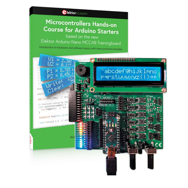
Bouw uw eigen projecten met het Elektor Arduino Nano MCCAB Training Board
De microcontroller is waarschijnlijk het meest fascinerende onderwerp van de moderne elektronica. Door de veelheid aan functies die hij op zijn chip combineert is het een universeel multi-tool voor ontwikkelaars om hun projecten mee te bouwen. Vrijwel elk dagelijks gebruikt apparaat wordt tegenwoordig bestuurd door een microcontroller. Voor een elektronica-leek is het realiseren van de eigen ideeën met een microcontroller echter tot nu toe een utopie gebleven vanwege de complexiteit ervan. Het Arduino-concept heeft het gebruik van microcontrollers sterk vereenvoudigd, zodat zelfs onervaren starters nu hun eigen elektronica ideeën kunnen realiseren met een microcontroller.
Book & Hardware in de bundel: 'Leren door te doen'
Het boek, dat ook in de bundel zit, leert ons hoe je zelfs zonder veel ervaring met elektronica en programmeertalen je eigen projecten met een microcontroller kunt bouwen. Het is een echte hands-on cursus microcontrollers voor starters. Want na een beschrijving van het inwendige van de microcontroller en een introductie in de programmeertaal C, ligt de focus van de cursus op praktische oefeningen. De lezer bouwt de nodige kennis op met 'leren door te doen': in het uitgebreide praktische gedeelte van het boek, met 12 projecten en 46 oefeningen, wordt het geleerde in het voorste deel van het boek met veel voorbeelden onderbouwd. Elke oefening wordt gevolgd door een uitgewerkt voorbeeld met uitleg en toelichting, wat de lezer helpt om de vraagstukken op te lossen en met de eigen oplossing te vergelijken.
Arduino IDE
De Arduino IDE is een software ontwikkelomgeving die gratis op de eigen pc kan worden gedownload, en die alle software bevat die nodig is voor uw eigen microcontroller-projecten. U schrijft de programma's ('apps') met de editor van de IDE in de programmeertaal C. En U vertaalt ze naar bits en bytes die de microcontroller begrijpt met behulp van de ingebouwde compiler van de Arduino IDE. En kunt ze vervolgens via een USB-kabel laden naar het geheugen van de microcontroller op het Elektor Arduino MCAB Nano Training Board.
Externe sensoren, motoren of schakelingen checken of besturen
Naast een Arduino Nano microcontroller module bevat het Elektor Arduino Nano MCCAB Training Board ook alle componenten die nodig zijn voor de oefeningen, zoals LED’s, schakelaars, drukknoppen, buzzer enz. Ook externe sensoren, motoren of modules kunnen worden gecheckt of bestuurd met dit microcontroller-trainingssysteem.
Specificaties (Arduino Nano Training Board MCCAB)
Voeding
Via de USB-aansluiting van de aangesloten pc of een externe voeding (niet inbegrepen)
Spanning
+5 Vcc
Ingangsspanning
Alle ingangen
0 V tot +5 V
VX1 en VX2
+8 V tot +12 V (alleen bij gebruik van een externe voeding)
Hardware
LCD
2x16 karakters
Potentiometer P1 & P2
JP3: Selectie van de werkspanning van P1 & P2
Verdelers
SV4: Verdeler voor de werkspanningenSV5, SV6: Verdelers voor de in-/uitgangen van de microcontroller
Schakelaars en knoppen
RESET knop op de Arduino Nano module; 6x drukknop schakelaars K1 ... K6; 6x Schuifschakelaars S1 ... S6; JP2: Jumper van de schakelaars met de ingangen van de microcontroller
Buzzer
Piezo buzzer ‘Buzzer1’ met jumper op JP6
Indicator LED’s
11 x LED: Status indicator voor de ingangen/uitgangen LED L op de Arduino Nano module, aangesloten op GPIO D13 JP6; Aansluiting van LED's LD10 ... LD20 met GPIO's D2 ... D12
Seriële interfacesSPI & I²C
JP4: Selectie van het signaal op pin X van de SPI-connector SV12 SV9 naar SV12: SPI-interface (3,3 V/5 V) of I²C-interface
Uitgangen voor externe apparaten
SV1, SV7: Geschakelde uitgang (maximaal +24 V/160 mA, extern aangesloten) SV2: 2x13 pinnen voor aansluiting van externe modules
3x3 LED matrix(9 rode LED's)
SV3: Kolommen van de 3x3 LED matrix (uitgangen D6 ... D8) JP1: Verbinding van de rijen met de GPIO's D3 ... D5
Software
MCCABLib library
Controle van hardware componenten (schakelaars, knoppen, LED's, 3x3 LED matrix, buzzer) op het MCCAB Training Board
Werktemperatuur
Tot +40 °C
Afmetingen
100 x 100 x 20 mm
Specificaties (Arduino Nano)
Microcontroller
ATmega328P
Architectuur
AVR
Spanning
5 V
Flash memory
32 KB, waarvan 2 KB gebruikt door de bootloader
SRAM
2 KB
Kloksnelheid
16 MHz
Analoge IN Pinnen
8
EEPROM
1 KB
DC stroom per I/O-pin
40 mA op één I/O-pin, totaal maximaal 200 mA op alle pinnen samen
Ingangsspanning
7-12 V
Digitale I/O-pinnen
22 (waarvan 6 PWM)
PWM Uitgangen
6
Stroomverbruik
19 mA
Afmetingen
18 x 45 mm
Gewicht
7 g
Inbegrepen
Elektor Arduino Nano MCCAB Training Board
Arduino Nano
Boek: Microcontrollers Hands-on Course for Arduino Starters
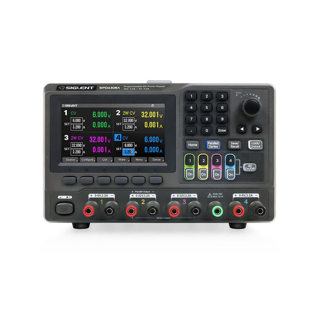
The Siglent SPD4306X is a 4-channel DC Linear Programmable Power Supply equipped with a 4.3-inch TFT-LCD display, friendly human-machine interface, and excellent performance indicators. Real-time waveform display provides engineers with an informative user interface.
SPD4306X offers a total output power of 400 W with a resolution of 1 mV/1 mA. The maximum voltage and current for each channel are as follows:
CH1: 15 V/1.5 A
CH2: 30 V/6 A
CH3: 30 V/6 A
CH4: 15 V/1 A
Kenmerken
Rated output power: 400 W
Rated voltage: 32 V, 12 V, 30 V
Up to four high-precision power supplies with independent controllable outputs, supporting CH2 and CH3 series and parallel connections
Clear graphical interface with waveform and timer display modes
5-digit voltage and current display with minimum resolution of 1 mV, 1 mA
Fast output response time: <50us
The high current channel support remote voltage compensation sense function. The maximum compensation voltage is 0.6 V
Overvoltage protection and overcurrent protection or safe and accurate operation
Equipped with a 4.3-inch TFT-LCD display (480 x 272 resolution)
USB and LAN standard communication
USB-GPIB module is optional
Excellent channel density with up to 4 channels in a 3U half rack package
Internal data storage for setups and parameters
Embedded Web Server with instrument communication that doesn’t require software installation
Fully SCPI programming command set support as well as a LabView driver for remote control and system automation
Specificaties
SPD4323X
SPD4121X
SPD4306X
Channel Output
CH1: Voltage 0 to 6 V Current 0 to 3.2 ACH2: Voltage 0 to 32 V Current 0 to 3.2 ACH3: Voltage 0 to 32 V Current 0 to 3.2 ACH4: Voltage 0 to 6 V Current 0 to 3.2 A
CH1: Voltage 0 to 15 V Current 0 to 1.5 ACH2: Voltage 0 to 12 V Current 0 to 10 ACH3: Voltage 0 to 12 V Current 0 to 10 ACH4: Voltage 0 to 15 V Current 0 to 1.5 A
CH1: Voltage 0 to 15 V Current 0 to 1.5 ACH2: Voltage 0 to 30 V Current 0 to 6 ACH3: Voltage 0 to 30 V Current 0 to 6 ACH4: Voltage 0 to 15 V Current 0 to 1 A
Resolution
1 mV, 1 mA
1 mV, 1 mA
1 mV, 1 mA
Setting Accuracy
Voltage: ±(0.03% of reading+10) mV, Current: ±(0.3% of reading+10) mA
Voltage: ±(0.03% of reading+10) mV, Current: ±(0.3% of reading+10) mA
Voltage: ±(0.03% of reading+10) mV, Current: ±(0.3% of reading+10) mA
Readback Accuracy
Voltage: ±(0.03% of reading+10) mV, Current: ±(0.3% of reading+10) mA
Voltage: ±(0.03% of reading+10) mV, Current: ±(0.3% of reading+10) mA
Voltage: ±(0.03% of reading+10) mV, Current: ±(0.3% of reading+10) mA
Display
4.3" TFT-LCD 5-digit voltage and current display
4.3" TFT-LCD 5-digit voltage and current display
4.3" TFT-LCD 5-digit voltage and current display
Output power
240 W
285 W
400 W
Inbegrepen
1x Siglent SPD4306X Power Supply
1x Power cord (EU)
1x Output test cord (3 A)
1x USB cable
1x Quick start guide
Downloads
Datasheet
Manual
Quick start
The Siglent SDS1204X-E is a powerful 200 MHz four-channel oscilloscope that is built on the same platform as the very popular SDS1202X-E but with several significant improvements, including two 1 GSa/s ADCs and two 14 Mpt memory modules. Waveform capture rates are up to 100,000 wfms/s in normal mode and 400,000 wfms/s in sequence mode. The SDS1000X-E scopes feature a large 7” 256-level color display with intensity grading and color temperature features.
Specificaties
Bandwidth
200 MHz
Sampling Rate (Max.)
1 GSa/s
Channels
2CH+EXT4CH
Memory Depth (Max.)
7 Mpts/CH (not interleave mode); 14 Mpts/CH (interleave mode)
Waveform Capture Rate (Max.)
100,000 wfms/s (normal mode), 400,000 wfms/s (sequence mode)
Trigger Types
Edge, Slope, Pulse width, Window, Runt, Interval, Dropout, Pattern, Video
Serial Trigger (Standard)
I2C, SPI, UART/RS232, CAN, LIN
Decode Type (Standard)
I2C, SPI, UART/RS232, CAN, LIN
16 Digital Channels (four channel series only, option)
Maximum waveform capture rate up to 1 GSa/s, Record length up to 14 Mpts/CH
USB AWG module (four channel series only, option)
One channel, 25 MHz, sample rate of 125 MHz, wave length of 16 kpts
Bode plot ( four channel series only)
Minimum start frequency of 10 Hz, minimum scan bandwith of 500 Hz, maximum scan bandwidth of 120 MHz (dependent on Oscilloscope and AWG bandwidth), 500 maximum scan frequency points
USB WIFI adapter (four channel series only, option)
802.11b/g/b, WPA-PSK, the adapter must be supplied by Siglent to ensure proper functioning
Downloads
Datasheet
Manual
Programming Guide
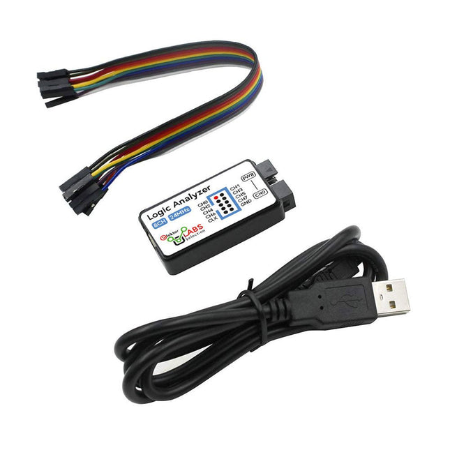
Deze USB Logic Analyzer is een 8-kanaals logic analyzer met elke ingang bedoeld voor het op twee manieren opnemen van analoge data. Hij is perfect voor het debuggen en analyseren van signalen zoals I²C, UART, SPI, CAN en 1-Wire. De analyzer bemonstert een digitale ingang die is aangesloten op een te testen apparaat (DUT) met een hoge bemonsteringssnelheid. De aansluiting op de PC gaat via USB.Specificaties
Kanalen
8 digitale kanalen
Maximale bemonsteringssnelheid
24 MHz
Maximale ingangsspanning
0 V ~ 5 V
Bedrijfstemperatuur
0°C ~ 70°C
Ingangsimpedantie
1 MΩ || 10 pF
Ondersteunde protocollen
I²C, SPI, UART, CAN, 1-wire, enz.
PC-aansluiting
USB
Afmetingen
55 x 28 x 14 mm
Inbegrepen
USB Logic Analyzer (8-kanaals, 24 MHz)
USB-kabel
Jumper Draad Lintkabel
DownloadsSoftware
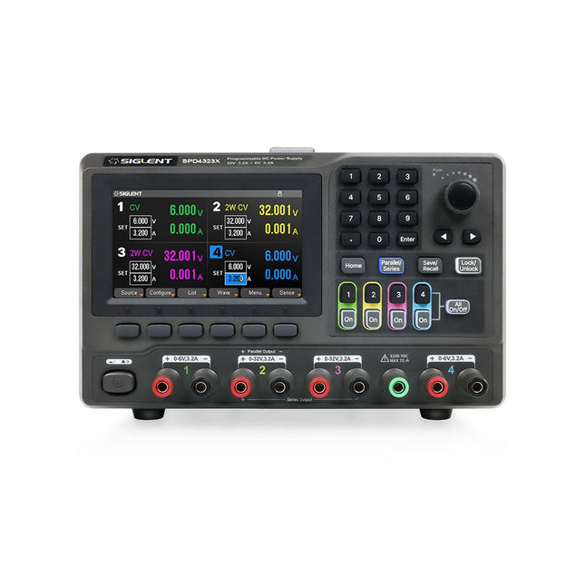
The Siglent SPD4323X is a 4-channel DC Linear Programmable Power Supply equipped with a 4.3-inch TFT-LCD display, friendly human-machine interface, and excellent performance indicators. Real-time waveform display provides engineers with an informative user interface.
SPD4323X offers a total output power of 240 W with a resolution of 1 mV/1 mA. The maximum voltage and current for each channel are as follows:
CH1: 6 V/3.2 A
CH2: 32 V/3.2 A
CH3: 32 V/3.2 A
CH4: 6 V/3.2 A
Kenmerken
Rated output power: 240 W
Rated voltage: 32 V, 12 V, 30 V
Up to four high-precision power supplies with independent controllable outputs, supporting CH2 and CH3 series and parallel connections
Clear graphical interface with waveform and timer display modes
5-digit voltage and current display with minimum resolution of 1 mV, 1 mA
Fast output response time: <50us
The high current channel support remote voltage compensation sense function. The maximum compensation voltage is 0.6 V
Overvoltage protection and overcurrent protection or safe and accurate operation
Equipped with a 4.3-inch TFT-LCD display (480 x 272 resolution)
USB and LAN standard communication
USB-GPIB module is optional
Excellent channel density with up to 4 channels in a 3U half rack package
Internal data storage for setups and parameters
Embedded Web Server with instrument communication that doesn’t require software installation
Fully SCPI programming command set support as well as a LabView driver for remote control and system automation
Specificaties
SPD4323X
SPD4121X
SPD4306X
Channel Output
CH1: Voltage 0 to 6 V Current 0 to 3.2 ACH2: Voltage 0 to 32 V Current 0 to 3.2 ACH3: Voltage 0 to 32 V Current 0 to 3.2 ACH4: Voltage 0 to 6 V Current 0 to 3.2 A
CH1: Voltage 0 to 15 V Current 0 to 1.5 ACH2: Voltage 0 to 12 V Current 0 to 10 ACH3: Voltage 0 to 12 V Current 0 to 10 ACH4: Voltage 0 to 15 V Current 0 to 1.5 A
CH1: Voltage 0 to 15 V Current 0 to 1.5 ACH2: Voltage 0 to 30 V Current 0 to 6 ACH3: Voltage 0 to 30 V Current 0 to 6 ACH4: Voltage 0 to 15 V Current 0 to 1 A
Resolution
1 mV, 1 mA
1 mV, 1 mA
1 mV, 1 mA
Setting Accuracy
Voltage: ±(0.03% of reading+10) mV, Current: ±(0.3% of reading+10) mA
Voltage: ±(0.03% of reading+10) mV, Current: ±(0.3% of reading+10) mA
Voltage: ±(0.03% of reading+10) mV, Current: ±(0.3% of reading+10) mA
Readback Accuracy
Voltage: ±(0.03% of reading+10) mV, Current: ±(0.3% of reading+10) mA
Voltage: ±(0.03% of reading+10) mV, Current: ±(0.3% of reading+10) mA
Voltage: ±(0.03% of reading+10) mV, Current: ±(0.3% of reading+10) mA
Display
4.3" TFT-LCD 5-digit voltage and current display
4.3" TFT-LCD 5-digit voltage and current display
4.3" TFT-LCD 5-digit voltage and current display
Output power
240 W
285 W
400 W
Inbegrepen
1x Siglent SPD4323X Power Supply
1x Power cord (EU)
1x Output test cord (3 A)
1x USB cable
1x Quick start guide
Downloads
Datasheet
Manual
Quick start
Deze bundel bevat alles wat u nodig hebt om direct aan de slag te gaan met het XIAO ESP32-C3 development board. Leer de basisprincipes van de ESP32-C3 en bouw praktische projecten met Wi-Fi, Bluetooth, sensoren, displays, PWM, Deep Sleep en nog veel meer.
Boek: Build Smart Projects with the XIAO ESP32-C3 Board
Het XIAO ESP32-C3 board combineert de ultracompacte vormfactor van de XIAO-serie met de uitgebreide mogelijkheden van de ESP32-C3-chip, inclusief geïntegreerde Wi-Fi en Bluetooth 5.0. Dit boek is een uitgebreide, praktische gids waarmee u het maximale uit dit krachtige en toch betaalbare development board kunt halen.
De auteur neemt de lezer mee van de basisprincipes tot geavanceerde projecten. Na het laten knipperen en dimmen van leds komen ADC en PWM aan bod voor nauwkeurige sensoraansluiting en PWM-gestuurde lichteffecten. Vervolgens gaat u aan de slag met praktische toepassingen, waaronder:
Een Wi-Fi-weerstation met OLED-display en actuele online weergegevens
Een ultrasone parkeerassistent met akoestische feedback
Een koelkastmonitor met klimaatsensoren en Deep Sleep voor jarenlang batterijgebruik
Een retro Pong-spel dat contactloos met een sensor wordt bestuurd
Een microfoongebaseerde party-app die reageert op handgeklap
En nog veel meer: lichtregeling, reactietijdmeting, analyse van de netfrequentie, bodemvochtmeting, sfeerverlichting met leds en 7-segmentdisplays
Seeed Studio XIAO ESP32C3
De Seeed Studio XIAO ESP32C3 is uitgerust met een sterk geïntegreerde ESP32-C3-chip, gebaseerd op een 32-bits RISC-V-processor met een viertraps pipeline die werkt met een kloksnelheid tot 160 MHz.
Het board beschikt over een sterk geïntegreerde ESP32-C3 SoC. De chip bevat een volledig 2,4-GHz Wi-Fi-subsysteem en ondersteunt daarmee Station-modus, SoftAP-modus, SoftAP & Station-modus en promiscuous-modus voor uiteenlopende Wi-Fi-toepassingen. Tegelijkertijd werkt de chip met een zeer laag energieverbruik en ondersteunt hij Bluetooth 5 en Bluetooth Mesh. Met 400 KB SRAM en 4 MB Flash biedt de chip voldoende programmeerruimte en volop mogelijkheden voor IoT-besturingstoepassingen.
Toepassingen
Internet of Things
Wearables
Gezondheidsmonitoring
Onderwijs
Energiezuinige netwerken
Snelle prototyping
Specificaties
Processor
ESP32-C3 SoC
RISC-V single-core 32-bit chip processor with a four-stage pipeline that operates at up to 160 MHz
Wireless
Complete 2.4GHz Wi-Fi subsystem
Bluetooth Low Energy 5.0/ Bluetooth Mesh
On-chip Memory
400 KB SRAM & 4 MB Flash
Interface
1x UART, 1x I²C, 1x SPI, 11x GPIO (PWM), 4x ADC
1x Reset button, 1x Boot button
Power (Typ.)
Max 3.3 V Output Current: 500 mA Test Condition: BAT Pin Input @ 3.8 V Source Capability: 3 A
Charging current: 380 mA(Fast) / 40 mA(Trickle)
Input voltage (VIN): 5 VInput voltage (BAT): 3.7 V
Deep Sleep Power Consumption
Deep Sleep Mode: 44 μA
Wi-Fi Enabled Power Consumption
Active Mode: 75 mA
Modem-sleep Mode: 25 mA
Light-sleep Mode: 4 mA
BLE Enabled Power Consumption
Modem-sleep Mode: 27 mA
Light-sleep Mode: 10 mA
Dimensions
21 x 17.8 mm
Inbegrepen
1x Seeed Studio XIAO ESP32C3
1x Antenne
2x 7-pins header
Downloads
Wiki
Datasheet
Deze bundel bevat:
Boek: Build Smart Projects with the XIAO ESP32-C3 Board (t.w.v. € 35)
Board: Seeed Studio XIAO ESP32C3 (t.w.v. € 10)
Hoogwaardig LoRa-communicatieapparaat
De Elecrow ThinkNode M5 is een compact, draagbaar LoRa-communicatieapparaat dat is ontworpen voor berichtenverkeer en het delen van locaties buiten het bereik van mobiele netwerken (off-grid) en voor gebruik in de buitenlucht. Het apparaat wordt aangestuurd door een ESP32-S3-processor en een SX1262 LoRa-chip, is voorzien van vooraf geïnstalleerde Meshtastic-firmware en kan eenvoudig via Bluetooth worden geconfigureerd met de officiële Meshtastic-app.
De geïntegreerde multi-GNSS-module ondersteunt GPS, GLONASS, BeiDou en QZSS voor betrouwbare positionering en het delen van locaties. Berichten en apparaatgegevens worden weergegeven op het energiezuinige 1,54-inch e-paper-scherm, terwijl de ingebouwde oplaadbare accu van 1.200 mAh zorgt voor langdurig mobiel gebruik.
Dankzij de geïntegreerde LoRa-antenne, de compacte behuizing, de RTC en de ondersteuning voor zowel Meshtastic- als MeshCore-firmware is de ThinkNode M5 een praktische communicatieoplossing voor wandelen, kamperen, afgelegen locaties en noodsituaties waarin conventionele mobiele netwerken niet beschikbaar zijn.
Kenmerken
LoRa-communicatie
Multi-GNSS-positionering
Oplaadbare accu van 1200 mAh
1,54-inch e-paper-display
Ingebouwde RTC
Compatibel met MeshCore
Compatibel met Meshtastic
Specificaties
Hoofdprocessor (ESP32-S3)
CPU/SoC
Xtensa 32-bit LX7 dual-core processor, geklokt op maximaal 240 MHz
Systeemgeheugen
512 KB SRAM, 8 MB PSRAM
Opslag
4 MB Flash, 384 KB ROM
Firmware
Volledig compatibel met Meshtastic-firmware; signaaloverdracht via LoRa-modus
EPD (Electronic Paper Display)
Displaygrootte
1,54-inch EPD (monochroom E-Ink-scherm)
Displaymateriaal
E-Ink (Electronic Ink)
Resolutie
200 x 200
Driver-chip
SSD1681 (via SPI- of I²C-interface)
Volledige verversingstijd
2 s
Draadloze communicatie
Bluetooth
Bluetooth Low Energy en Bluetooth 5.0 (configuratie via telefoon)
LoRa
SX1262 LoRa-module, EU 868 MHz (externe antenne)
Hardware
Interfaces
USB-C, RP-SMA
Functies
GPS-locatie (GPS, GLONASS, BeiDou, QZSS), EPD-scherm, RTC, USB 2.0, PMU-energiebeheer (ingebouwde 1200 mAh-lithiumaccu), zoemer, enz.
Knoppen
Draaischakelaar, functieknop, paginaknop, GPS-schakelaar, resetknop
LED-indicator
Voeding, GPS/LoRa-indicatie
Overige
Voeding
5 V/1 A, ondersteunt voeding via USB of lithiumbatterij
Stroomverbruik
De maximale bedrijfsstroom bedraagt ongeveer 340 mA (CPU + LoRa-module); het verbruik in de energiezuinige modus bedraagt ongeveer 34 uA
Bedrijfstemperatuur
-10~50°C
Opslagtemperatuur
-20~60°C
Relatieve luchtvochtigheid
10-95% bij 40°C (niet-condenserend)
Behuizing
ABS-kunststof
Afmetingen
82 x 51,6 x 26,3 mm
Gewicht
81 g
Inbegrepen
1x Elecrow ThinkNode M5
1x LoRa-antenne
1x USB-C kabel
1x Manual
Downloads
Manual