
Zoekresultaten voor "siglent OR sag1021 OR function OR arbitrary OR waveform OR generator OR 25 OR mhz"
-

Elektor Bundles Schnelleinstieg in die Elektronik (Bundle)
Der Einstieg in die Elektronik ist einfacher, als Sie denken! Mit diesem Bundle – bestehend aus Buch und Experimentierkit – entdecken Sie die Grundlagen der Elektro- und Elektroniktechnik Schritt für Schritt. Anhand spannender Experimente lernen Sie praxisnah und verständlich, ganz ohne komplizierte Fachbegriffe oder langwierige Berechnungen. So sind Sie schon bald in der Lage, Ihre eigenen Elektronikprojekte umzusetzen! Das Kit enthält alle notwendigen Komponenten, um die meisten im Buch beschriebenen Schaltungen direkt auf dem Steckbrett aufzubauen und praktisch zu erproben. Das Kit kann selbstverständlich auch ohne das Buch zum Aufbau anderer Schaltkreise und zur Durchführung eigener Experimente verwendet werden. Inhalt des Kits 1x 39 Ω, 1 W Widerstand 1x 47 Ω Widerstand 1x 180 Ω Widerstand 1x 330 Ω Widerstand 3x 1 kΩ Widerstand 1x 2,2 kΩ Widerstand 1x 3,9 kΩ Widerstand 1x 6,8 kΩ Widerstand 1x 10 kΩ Widerstand 1x 15 kΩ Widerstand 1x 22 kΩ Widerstand 1x 33 kΩ Widerstand 1x 47 kΩ Widerstand 1x 56 kΩ Widerstand 1x 82 kΩ Widerstand 1x 120 kΩ Widerstand 1x 680 kΩ Widerstand 2x 100 kΩ Widerstand 1x 10 kΩ Trimmer 1x 10 kΩ Linearpotentiometer 1x 100 kΩ Linearpotentiometer 1x LDR 1x 1 nF Keramikkondensator 2x 10 nF Keramikkondensator 1x 100 nF Keramikkondensator 1x 1 µF, 25 V Aluminium-Elektrolytkondensator 2x 10 µF, 25 V Aluminium-Elektrolytkondensator 1x 100 µF, 25 V Aluminium-Elektrolytkondensator 1x 470 µF, 25 V Aluminium-Elektrolytkondensator 1x 1000 µF, 25 V Aluminium-Elektrolytkondensator 1x RGB-LED, Common-Cathode (CC) 1x 1N4148 Kleinsignaldiode 1x 1N4733A 5,1 V, 1 W Zenerdiode 3x LED, rot 2x BC337 NPN-Transistor 1x IRFZ44N N-Kanal-MOSFET 2x NE555-Timer 1x LM393-Komparator 1x 74HCT08 Quad-AND-Gatter 3x Tastschalter 2x SPDT-Schalter 1x Relais, SPDT, 9 VDC 1x Aktiver Summer 1x Passiver Summer 50 cm Massivdraht, 16 AWG, ohne Mantel 2x PP3 9 V Batterieclip 1x Steckbrett 20x Überbrückungskabel Dieses Bundle enthält: Buch: Schnelleinstieg in die Elektronik (Einzelpreis: 45 €) Kit: Schnelleinstieg in die Elektronik (Wert: 45 €)
€ 89,95€ 69,95Beste prijs
-

Siglent Siglent SDS1104X-E 4-kanaals Oscilloscoop (100 MHz)
The Siglent SDS1104X-E employs a new generation of SPO (Super Phosphor Oscilloscope) technology that provides excellent signal fidelity and performance. The system noise is also lower than similar products in the industry. It comes with a minimum vertical input range of 500 uV/div, an innovative digital trigger system with high sensitivity and low jitter, and a waveform capture rate of 400,000 frames/ sec (sequence mode). The SDS1104X-E also employs a 256-level intensity grading display function and a color temperature display mode not found in other models in this class. SIGLENT’s latest oscilloscopes offering supports multiple powerful triggering modes including serial bus triggering. Serial decoding is free and includes IIC, SPI, UART, CAN, and LIN. History waveform recording and sequential triggering enable extended waveform recording and analysis. Another powerful addition is the new 1 Mpt FFT math function that gives the SDS1104X-E very high frequency resolution when observing signal spectra. Kenmerken Intelligent trigger: Edge, Slope, Pulse Width, Window, Runt, Interval, Timeout (Dropout), and Pattern Free Serial bus triggering and decoding:IIC, SPI, UART, RS232, CAN, and LIN Video triggers and supports HDTV Low background noise and 500 ?V / div to 10 V / div voltage scales 10 types of one-button shortcuts, supports Auto Setup, Default, Cursors, Measure, Roll, History, Display/Persist, Clear Sweep, Zoom and Print Segmented acquisition (Sequence) mode, dividing the maximum record length into multiple segments (up to 80,000), according to trigger conditions set by the user, with a very small dead time segment to capture the qualifying event. History waveform record (History) function, the maximum recorded waveform length is 80,000 frames Automatic measurement function on 38 parameters, supports Statistics, Gating measurement, Math measurement, History measurement and Ref measurement 1 Mpts FFT True measurement and math can use all 14 Mpts of memory Preset key can be customized for user settings or factory “defaults” Security Erase mode Highspeed hardware based Pass/ Fail function Large 7-inch TFT-LCD display with 800 * 480 resolution Multiple interface types: USB Host, USB Device (USB-TMC), LAN (VXI-11), Pass / Fail, Trigger Out Supports SCPI remote control commands Multi-language display and embedded help Browser control/onboard webpage for software free monitoring (4 channel models only) Inbegrepen 1x Siglent SDS1104X-E Oscilloscope 4x 100 MHz probes 1x Guarantee Card 1x Power Cord 1x USB Cable 1x Quick Start Guide Downloads Datasheet Manual Programming Guide
€ 508,71
-

Siglent Siglent SDS1204X-E 4-kanaals Oscilloscoop (200 MHz)
The Siglent SDS1204X-E is a powerful 200 MHz four-channel oscilloscope that is built on the same platform as the very popular SDS1202X-E but with several significant improvements, including two 1 GSa/s ADCs and two 14 Mpt memory modules. Waveform capture rates are up to 100,000 wfms/s in normal mode and 400,000 wfms/s in sequence mode. The SDS1000X-E scopes feature a large 7” 256-level color display with intensity grading and color temperature features. Specificaties Bandwidth 200 MHz Sampling Rate (Max.) 1 GSa/s Channels 2CH+EXT4CH Memory Depth (Max.) 7 Mpts/CH (not interleave mode); 14 Mpts/CH (interleave mode) Waveform Capture Rate (Max.) 100,000 wfms/s (normal mode), 400,000 wfms/s (sequence mode) Trigger Types Edge, Slope, Pulse width, Window, Runt, Interval, Dropout, Pattern, Video Serial Trigger (Standard) I2C, SPI, UART/RS232, CAN, LIN Decode Type (Standard) I2C, SPI, UART/RS232, CAN, LIN 16 Digital Channels (four channel series only, option) Maximum waveform capture rate up to 1 GSa/s, Record length up to 14 Mpts/CH USB AWG module (four channel series only, option) One channel, 25 MHz, sample rate of 125 MHz, wave length of 16 kpts Bode plot ( four channel series only) Minimum start frequency of 10 Hz, minimum scan bandwith of 500 Hz, maximum scan bandwidth of 120 MHz (dependent on Oscilloscope and AWG bandwidth), 500 maximum scan frequency points USB WIFI adapter (four channel series only, option) 802.11b/g/b, WPA-PSK, the adapter must be supplied by Siglent to ensure proper functioning Downloads Datasheet Manual Programming Guide
€ 781,44
-

OWON OWON VDS1022I 2-ch USB-oscilloscoop (25 MHz)
De OWON VDS1022I 2-kanaals USB-oscilloscoop (25 MHz) is een oscilloscoop voor gebruik met een computer. Hij wordt van voeding voorzien via USB en heeft een klein formaat, waardoor hij gemakkelijk mee te nemen is. De oscilloscoop is zeer betaalbaar. Hij heeft een afgeschermde USB-aansluiting, waardoor storing wordt verminderd en de computer wordt beschermd tegen overspanning. De multipoort op de scoop kan worden gebruikt voor externe triggering, trigger out of Pass / Fail uitgang.Kenmerken 25 MHz bandbreedte, en max. 1 GS/s real-time sample rate 10M recordlengte Gebruiksvriendelijke UI: FFT, of X-Y, en golfvorm 2 weergaven op hetzelfde scherm Multi-trigger optie: flank, video, slope, puls en afwisselend USB isolatie - minder signaalverstoring, meer pc-bescherming USB busvoeding en LAN afstandsbediening (optioneel) Ultradunne behuizing, gemakkelijk draagbaar Specificaties Bandbreedte 25 MHz Kanalen 2+1 (multi) Sample Rate 100 MSa/s Horizontal schaal (s/div) 5 ns/div?100s/div, in stappen van 1?2?5 Opname lengte 5K Max ingangsspanning 400 V (PK - PK) (DC+AC, PK - PK) 40 V (PK - PK) (DC+AC, PK - PK) Verticale resolutie (A/D) 8 bits (2 kanalen tegelijkertijd) Model VDS1022I Verticale gevoeligheid 5 mV/div?5 V/div Triggertype Edge, Pulse, Video, Slope, en Afwisselend Trigger mode Auto, Normaal, en Enkelvoudig Acquisition Mode Sample, Peak Detect, en Gemiddeld Golfvorm berekeningen ?, ?, ×, ÷, invert, FFT Communicatie Interface USB 2.0 (geïsoleerd) Multifunctioneel Interface Signaltype Level standard TTL Voeding 5,0 V/1 A Stroomverbruik ?2.5 W Afmetinegn (B × H × D) 170 x 120 x 18 mm Gewicht 0,26 kg Inbegrepen 1x OWON VDS1022I oscilloscoop 1x CD-ROM 1x Snelstartgids 2x Oscilloscoop probe 1x Probe 1x Voedingsadapter 1x USB kabel 1x Silicone beschermers voor de behuizing 1x Stroomkabel Downloads Datasheet Gebruiksaanwijzing SCPI protocol USB driver
€ 119,00
-
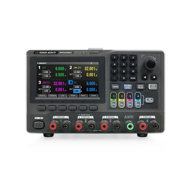
Siglent Siglent SPD4306X 4-kanaals Voeding (400 W)
The Siglent SPD4306X is a 4-channel DC Linear Programmable Power Supply equipped with a 4.3-inch TFT-LCD display, friendly human-machine interface, and excellent performance indicators. Real-time waveform display provides engineers with an informative user interface. SPD4306X offers a total output power of 400 W with a resolution of 1 mV/1 mA. The maximum voltage and current for each channel are as follows: CH1: 15 V/1.5 A CH2: 30 V/6 A CH3: 30 V/6 A CH4: 15 V/1 A Kenmerken Rated output power: 400 W Rated voltage: 32 V, 12 V, 30 V Up to four high-precision power supplies with independent controllable outputs, supporting CH2 and CH3 series and parallel connections Clear graphical interface with waveform and timer display modes 5-digit voltage and current display with minimum resolution of 1 mV, 1 mA Fast output response time: <50us The high current channel support remote voltage compensation sense function. The maximum compensation voltage is 0.6 V Overvoltage protection and overcurrent protection or safe and accurate operation Equipped with a 4.3-inch TFT-LCD display (480 x 272 resolution) USB and LAN standard communication USB-GPIB module is optional Excellent channel density with up to 4 channels in a 3U half rack package Internal data storage for setups and parameters Embedded Web Server with instrument communication that doesn’t require software installation Fully SCPI programming command set support as well as a LabView driver for remote control and system automation Specificaties SPD4323X SPD4121X SPD4306X Channel Output CH1: Voltage 0 to 6 V Current 0 to 3.2 ACH2: Voltage 0 to 32 V Current 0 to 3.2 ACH3: Voltage 0 to 32 V Current 0 to 3.2 ACH4: Voltage 0 to 6 V Current 0 to 3.2 A CH1: Voltage 0 to 15 V Current 0 to 1.5 ACH2: Voltage 0 to 12 V Current 0 to 10 ACH3: Voltage 0 to 12 V Current 0 to 10 ACH4: Voltage 0 to 15 V Current 0 to 1.5 A CH1: Voltage 0 to 15 V Current 0 to 1.5 ACH2: Voltage 0 to 30 V Current 0 to 6 ACH3: Voltage 0 to 30 V Current 0 to 6 ACH4: Voltage 0 to 15 V Current 0 to 1 A Resolution 1 mV, 1 mA 1 mV, 1 mA 1 mV, 1 mA Setting Accuracy Voltage: ±(0.03% of reading+10) mV, Current: ±(0.3% of reading+10) mA Voltage: ±(0.03% of reading+10) mV, Current: ±(0.3% of reading+10) mA Voltage: ±(0.03% of reading+10) mV, Current: ±(0.3% of reading+10) mA Readback Accuracy Voltage: ±(0.03% of reading+10) mV, Current: ±(0.3% of reading+10) mA Voltage: ±(0.03% of reading+10) mV, Current: ±(0.3% of reading+10) mA Voltage: ±(0.03% of reading+10) mV, Current: ±(0.3% of reading+10) mA Display 4.3" TFT-LCD 5-digit voltage and current display 4.3" TFT-LCD 5-digit voltage and current display 4.3" TFT-LCD 5-digit voltage and current display Output power 240 W 285 W 400 W Inbegrepen 1x Siglent SPD4306X Power Supply 1x Power cord (EU) 1x Output test cord (3 A) 1x USB cable 1x Quick start guide Downloads Datasheet Manual Quick start
€ 1.101,10
-

tinySA tinySA Ultra+ ZS407 Spectrumanalyzer
The tinySA Ultra+ ZS-407 is a compact, handheld spectrum analyzer and signal generator. Covering 100 kHz to 7.3 GHz in Ultra mode, it lets you visualize and analyze RF signals from HF right through many modern wireless bands – and can even spot signals up to ~12 GHz thanks to harmonic tracking. The intuitive 4-inch resistive touchscreen and rechargeable battery make it great for fieldwork, while features like a built-in signal generator, switchable bandpass filters, step attenuator, USB-PC control and auto-calibration add serious versatility. Kenmerken Screen size: 4 inch (480 x 320) Spectrum Analyzer for 0.1-900 MHz or, with Ultra mode enabled up to 7.3 GHz, level calibrated up to 7.3 GHz. Can observe signals up to 12 GHz Signal Generator with sine wave output between 0.1-900 MHz or square wave up to 6.3 GHz or RF test signal output up to 7.3 GHz when not used as Spectrum Analyzer. Switchable resolution bandpass filters from 200 Hz to 850 kHz Built-in 20 dB optional LNA Color display showing max 450 points providing gapless covering up to the full frequency range. MicroSD card slot for storing measurements, settings and screen captures. Specificaties (Spectrumanalyzer) Input frequency range from 100 kHz to 900 MHz in normal mode and up to 7.3 GHz with ULTRA mode enabled Input impedance 50 ohm when input attenuation set to 10 dB or more. Selectable manual and automatic input attenuation between 0 dB and 31 dB in 1 dB steps when LNA not active Maximum +/-5V DC input Absolute maximum input level of +6 dBm with 0 dB internal attenuation Absolute maximum short term peak input power of +20 dBm with 30 dB internal attenuation Suggested maximum input power of +0 dBm with internal attenuation in automatic mode For best measurements keep input power below -25 dBm Input Intercept Point of third order modulation products (IIP3) of +15 dBm with 0 dB internal attenuation 1 dB compression point at -1 dBm with 0 dB internal attenuation Power detector resolution of 0.5 dB and linearity versus frequency of ±2 dB below 5.3 GHz, ±5dB between 5.3 GHz and 6 GHz Minimum burst length for correct level measurement at 850 kHz RBW in zero span mode of 50 microseconds Absolute power level accuracy after power level calibration of ±2 dB Built-in optional 20 dB LNA with Noise Figure of 5 dB up to 6 GHz Lowest discernible signal without LNA at 30 MHz using a resolution bandwidth of 30 kHz of -102 dBm Lowest discernible signal with LNA at 30 MHz using a resolution bandwidth of 200 Hz of -145 dBm Frequency accuracy equal to the selected resolution bandwidth Phase noise at 30 MHz of -108 dB/Hz at 100 kHz offset and -115 dB/Hz at 1MHz offset Spur free dynamic range when using a 30 kHz resolution bandwidth of 70 dB Resolution filters with a width of 0.2, 1, 3, 10, 30, 100, 300, 600 and 850 kHz On screen resolution of 51, 101, 145, 290 or 450 measurement points. Scanning speed of over 1000 points/second using largest resolution filters. Automatic optimization of actual scanning points to ensure coverage of the whole scan range regardless of the chosen resolution bandwidth Spur suppression option for assessing if certain signals are internally generated or actually present in the input signal Headphone output for listening to the demodulated audio (AM only). Stereo connector with or without microphone, high impedance is louder, short protected Specificaties (Signaalgenerator) Sine wave output with harmonics below -40 dB of fundamental from 100 kHz to 900 MHz Output level selectable in 1 dB steps between -115 dBm and -19 dBm Above 800 MHz choice of two output modes: Cleanest signal mode: square wave, up to 6 GHz with coarse frequency steps and less accurate output level Highest accuracy mode: reduced harmonics with possibly strong spurs up to 7.3 GHz with frequency resolution equal to below 800 MHz and fine output level steps Level accuracy ±2 dB up to 800 MHz between -72 dBm and -19 dBm, less accuracy below -72 dBm, even less accuracy below -110 dBm Output frequency resolution 57.2 Hz Optional AM or FM modulation frequencies between 50 Hz and 5 kHz (AM) or 1 kHz (FM) or sweep over selectable frequency span AM modulation depth between 10% and 100% FM deviation between 1 kHz and 300 kHz Optional output level sweep over maximum the entire output level range Inbegrepen 1x tinySA Ultra+ ZS407 Spectrum Analyzer 2x SMA connection cables 1x Barrel connector 1x Antenna with SMA connector 1x USB-C cable 1x microSD card (32 GB) Downloads Wiki
€ 196,02
-

Elektor Bundles Bundle: Logic Analyzer im Einsatz (Buch) + USB Logic Analyzer (8 Kanäle, 24 MHz)
USB-Logikanalysatoren am PC mit Arduino, Raspberry Pi und Co Schritt-für-Schritt-Anleitungen führen Sie in die Analyse moderner Protokolle von I²C, SPI, UART, RS-232, NeoPixel, WS28xx, HD44780 und 1-Wire Protokollen ein. Anhand von zahlreichen Experimentierschaltungen mit dem Raspberry Pi Pico, Arduino Uno und dem Bus Pirate üben Sie die praxisnahe Anwendung gängiger USB-Logikanalysatoren ein. Alle in diesem Buch vorgestellten Experimentierschaltungen wurden vollständig getestet und sind funktionsfähig. Die notwendigen Programmlistings sind enthalten, es sind keine besonderen Programmier- oder Elektronikkenntnisse für diese Schaltungen notwendig. Es werden die Programmiersprachen MicroPython und C mit den Entwicklungsumgebungen Thonny und Arduino IDE eingesetzt. Dieses Buch verwendet mehrere Modelle flexibler und weit verbreiteter USB-Logikanalysatoren und zeigt die Stärken und Schwächen jeder Preisklasse. Sie werden kennenlernen, welche Kriterien für Ihre Arbeit wichtig sind und in der Lage sein, das für Sie passende Gerät zu finden. Egal ob Arduino, Raspberry Pi oder Raspberry Pi Pico: Die abgebildeten Beispielschaltungen ermöglichen einen schnellen Start in die Protokollanalyse und können auch als Grundlage für eigene weitere Experimente dienen. Sie werden alle wichtigen Begriffe und Zusammenhänge kennenlernen, eigene Experimente durchführen, selbstständig Protokolle analysieren und nach der Lektüre dieses Buches – im Bereich der digitalen Signale und Protokolle – ein umfassendes Wissen aufgebaut haben. USB Logic Analyzer (8 Kanäle, 24 MHz) Dieser USB Logic Analyzer ist ein 8-Kanal-Logikanalysator, bei dem jeder Eingang doppelt für die analoge Datenaufzeichnung dient. Es eignet sich perfekt zum Debuggen und Analysieren von Signalen wie I²C, UART, SPI, CAN und 1-Wire. Dabei wird ein digitaler Eingang, der mit einem zu testenden Gerät (DUT) verbunden ist, mit einer hohen Abtastrate abgetastet. Die Verbindung zum PC erfolgt via USB. Technische Daten Kanäle 8 digitale Kanäle Maximale Abtastrate 24 MHz Maximale Eingangsspannung 0 V ~ 5 V Betriebstemperatur 0°C ~ 70°C Eingangsimpedanz 1 MΩ || 10 pF Unterstützte Protokolle I²C, SPI, UART, CAN, 1-Wire etc. PC-Verbindung USB Abmessungen 55 x 28 x 14 mm Downloads Software Dieses Bundle enthält: Neues Buch "Logic Analyzer im Einsatz" (Einzelpreis: 32,80 €) USB Logic Analyzer (8 Kanäle, 24 MHz) (Einzelpreis: 12,95 €) USB-Kabel Jumper Wire Ribbon Kabel
€ 59,95€ 49,95Beste prijs
-
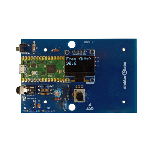
Elektor Labs Elektor AM-zender Kit
Bouw je eigen vintage radiozender De Elektor AM-zender kit maakt het mogelijk om audio te streamen naar vintage AM-radiotoestellen. Gebaseerd op een Raspberry Pi Pico microcontroller-module kan de AM-zender uitzenden op 32 frequenties in de AM-band, van 500 kHz tot 1,6 MHz in 32 stappen van ca. 35 kHz. De frequentie wordt gekozen met een potentiometer en weergegeven op een 0,96" OLED-display. Een drukknop maakt het mogelijk om de zendmodus te schakelen tussen Aan en Uit. Het bereik van de zender hangt af van de antenne. De ingebouwde antenne biedt een bereik van enkele centimeters, waardoor de AM-zender dicht bij of in de radio moet worden geplaatst. Een externe lusantenne (niet inbegrepen) kan worden aangesloten om het bereik te vergroten. De Elektor AM-zender kit wordt geleverd als een bouwpakket dat je zelf op de printplaat moet solderen. Kenmerken De printplaat is compatibel met een Hammond 1593N-behuizing (niet inbegrepen).Een 5 VDC-voeding met micro-USB-connector (bijv. een oude telefoonoplader) is nodig om de kit van stroom te voorzien (niet inbegrepen). Stroomverbruik: 100 mA. De Arduino-software (vereist het RP2040-boards-pakket van Earle Philhower) voor de Elektor AM-zenderkit plus meer informatie is beschikbaar op de Elektor Labs-pagina van dit project. Componentenlijst Weerstanden R1, R4 = 100 Ω R2, R3, R8 = 10 kΩ R5, R6, R9, R10, R11 = 1 kΩ R7 = optioneel (niet inbegrepen) P1 = potentiometer 100 kΩ, lineair Condensatoren C1 = 22 µF 16V C2, C4 = 10 nF C3 = 150 pF Diversen K1 = 4×1 pinheader K2, K3 = 3,5 mm-aansluiting Raspberry Pi Pico Drukknop, haaks gemonteerd 0,96" monochroom I²C OLED-display PCB 150292-1
€ 34,95€ 29,95Beste prijs
-

JOY-iT Joy-Pi Advanced Ontwikkelplatform (incl. Raspberry Pi 4, 8 GB)
De Joy-Pi Advanced is een compact en krachtig instrument waarmee je snel en eenvoudig je projecten kunt realiseren. Of je nu veel of weinig ervaring hebt, met de Joy-Pi Advanced kun je je creativiteit de vrije loop laten. Dankzij de compatibiliteit met een groot aantal platformen, waaronder Raspberry Pi, Raspberry Pi Pico, Arduino Nano, BBC micro:bit en NodeMCU ESP32, kun je eenvoudig en snel toegang krijgen tot het platform van je voorkeur. Daarnaast heeft de Joy-Pi Advanced meer dan 30 stations, lessen en modules, waardoor je een onbeperkt aantal manieren hebt om je projecten uit te voeren. Met het zelfontwikkelde leercentrum kun je niet alleen je vaardigheden verbeteren, maar ook nieuwe projecten maken. Het leercentrum biedt een schat aan informatie en tutorials die je stap voor stap door je projecten begeleiden. Joy-Pi Advanced wordt in het bijzonder gekenmerkt door zijn intelligente schakeleenheden, die een uitgebreid gebruik van de beschikbare pinnen mogelijk maken. In totaal zijn er drie schakeleenheden geïntegreerd, elk voorzien van 12 individuele schakelaars die zorgen voor een nauwkeurige aansturing van de aangesloten sensoren en modules. Dit systeem lost het bekende probleem van het beperkte aantal pinnen op dat optreedt bij conventionele microcontrollers. Met de schakeleenheden kun je een groot aantal sensoren en modules parallel aansturen door ze afzonderlijk aan en uit te schakelen. Dit simuleert meervoudige pintoewijzing, waardoor je het volledige vermogen van je projecten kunt benutten zonder afbreuk te doen aan de functionaliteit. Door onze innovatieve adapter boards en het micro:bit slot te combineren, bereiken we naadloze compatibiliteit met een breed scala aan microcontrollers zoals Raspberry Pi Pico, NodeMCU ESP32, micro:mit en Arduino Nano. De speciaal ontwikkelde adapterkaarten zijn zo ontworpen dat ze perfect passen bij de betreffende microcontroller. Door de microcontroller op het juiste adapterboard aan te sluiten en deze vervolgens in het micro:bit slot te steken, wordt de Joy-Pi Advanced snel en eenvoudig compatibel met de verschillende microcontrollers. Dit zorgt voor een naadloze integratie van het platform van je voorkeur en de mogelijkheid om de sterke punten van de verschillende microcontrollers te combineren in je projecten. Op deze manier kun je je volledig richten op je creatieve projecten zonder dat je je zorgen hoeft te maken over de compatibiliteit van verschillende microcontrollers. De Joy-Pi Advanced vereenvoudigt het ontwikkelproces en geeft je de mogelijkheid om je projecten flexibel en individueel te ontwerpen. Kenmerken Sterk geïntegreerd ontwikkelplatform & leercentrum Snel, eenvoudig & draadloos combineren van verschillende sensoren & actuatoren Installatieoptie voor Raspberry Pi 4 Compatibel met verschillende microcontrollers Zelfontwikkeld, didactisch leerplatform voor Raspberry Pi & Windows Specificaties Compatibel met Raspberry Pi 4, Arduino Nano, NodeMCU ESP32, BBC micro:bit, Raspberry Pi Pico Geïnstalleerde sensoren, actuatoren & componenten 39 Leerplatform Meer dan 40 items in de kennisdatabase, 10 projecten, 10 lessen, 14 visies Displays 7-segment display, 16x2 display, 1,8' TFT-display, 0,96" OLED-display, 8x8 RGB-matrix Sensoren DS18B20, schoksensor, hallsensor, barometer, geluidssensor, gyroscoop, PIR-sensor, Lichtbarrière, NTC, Lichtsensor, 6x aanraaksensor, kleurensensor, ultrasone afstandssensor, DHT11 temperatuur- & vochtigheidssensor Controle Joystick, 5x schakelaars, potentiometer, draaiencoder, 4x4 knoppenmatrix, relais, PWM-ventilator Motoren Servo-interface, Stappenmotorinterface, Trilmotor Meet- en conversiemodules Analoog-digitaalomzetter, niveauomzetter, voltmeter, variabele spanningsbron Andere onderdelen RTC real-time klok, zoemer, EEPROM-geheugen, infrarood ontvanger, breadboard, RFID-lezer Adapterkaarten Adapter voor NodeMCU ESP32, Arduino Nano & Raspberry Pi Pico, Board connectors voor Raspberry Pi & externe boards Elektronische onderdelen Infrarood afstandsbediening, RFID-chip, RFID-kaart, 6x krokodillenklemmen, microSD-kaartlezer, servomotor, stappenmotor, 32 GB microSD-kaart Onderdelen 40x weerstanden, 3x groene LED's, 3x gele LED's, 3x rode LED's, 1x transistor, 5x knoppen, 1x potentiometer, 2x condensatoren Andere accessoires Schroevenassortiment, schroevendraaier, accessoire-opbergtas, voeding & voedingskabel, servo bevestiging Stroomvoorziening Ingebouwde voeding: 36 W, 12 V, 3 A Behuizingsconnector: Kleine apparaat stekker C8 Spanningsuitgangen 12 V, 5 V, 3,3 V, variabele spanningsuitgang (2-11 V) Databussen & signaaluitgangen I²C, SPI, Analoog naar digitaal converter Batterij (RTC) CR2032 Afmetingen 327 x 200 x 52 mm Inbegrepen Raspberry Pi 4 (8 GB RAM) Downloads Joy-Pi website Datasheet Manual
€ 529,00€ 469,00Beste prijs
-

OWON OWON HDS2102s (3-in-1) 2-kanaals Oscilloscoop (100 MHz) + Multimeter + Signaalgenerator
De OWON HDS2102s is een draagbare 3-in-1 multifunctionele tester, die kan worden gebruikt als een 2-kanaals oscilloscoop met een bandbreedte van 100 MHz, multimeter en signaalgenerator. Het beschikt over een contrastrijk 3,5-inch kleurendisplay dat geschikt is voor onderhoud van buitenfaciliteiten, snelle metingen op locatie, onderhoud van auto's, stroomdetectie, enz. Kenmerken Oscilloscope + multimeter + waveform generator, multifunction in one 3.5-inch high-resolution, high-contrast color LCD display, suitable for outdoor use 18650 lithium battery, can work continuously for 3-6 hours USB Type-C interface, support power bank, support PC software connection Self-calibration function SCPI supported, facilitate secondary development Specificaties Bandwidth 100 MHz Channels 2-ch Oscilloscope + 1-ch Generator Sample Rate 500 MSa/s Acquisition Model Normal, Peak detect Record Length 8K Display 3.5-inch LCD Waveform Refresh Rate 10,000 wfrms/s Input Coupling DC, AC, and Ground Input Impedance 1 MΩ ±2%, in parallel with 16pF ±10pF Probe Attenuation Factors 1X,10X,100X,1000X,10000X Max. input Voltage 400 V (DC+AC, PK-PK, 1MΩ input impedance) (10:1 probe attenuation) Bandwidth Limit (typical) 20 MHz Horizontal Scale 2ns/div - 1000s/div, step by 1 - 2 - 5 Vertical Sensitivity 10mV/div - 10V/div Vertical Resolution 8 bits Trigger Type Edge Trigger Modes Auto, Normal, single Automatic Measurement Frequency, Period, Amplitude, Max, Min, Mean, PK-PK Cursor Measurement ΔV, ΔT, ΔT&ΔV between cursors Communication Interface USB-C Multimeter (Specificaties) Max. Resolution 20,000 counts Testing Mode Voltage, Current, Resistance, Capacitance, Diode, and Continuity test Input Impedance 10 MΩ Max Input Voltage AC 750 V, DC 1000 V Max Input Current DC: 10 A, AC: 10 A Diode 0-2 V Signaalgenerator (Specificaties) Frequency Output Sine 0.1 Hz - 25 MHz Square 0.1 Hz - 5MHz Ramp 0.1 Hz - 1 MHz Pulse 0.1 Hz - 5 MHz Arbitrary 0.1 Hz - 5 MHz Sampling Rate 125 MSa/s Channel 1-ch Amplitude Range (high impedance) 20 mVpp - 5 Vpp Waveform Length 8K Vertical Resolution 14 bits Output Impedance 50Ω Inbegrepen 1x OWON HDS2102s Oscilloscope 1x Power adapter 1x USB cable 1x Passive probes 2x Crocodile clip cable 1x Set of multimeter probes (one red and one black) 1x User manual 1x Probe correction adjustment knife Downloads User Manual Specifications SCPI Protocol Quick Guide Software
€ 187,57
-

Elektor Labs Elektor Low-noise Labvoeding
De low-noise labvoeding van Elektor is een volledig analoge, instelbare, symmetrische unit met gemiddeld vermogen, zonder schakelende of digitale componenten. De uitgangsspanning is instelbaar tussen 0 V en ±22 V, en de uitgangsstroom kan worden ingesteld van 0 A tot 1 A. Doordat elke vorm van schakeltechniek wordt vermeden, levert het ontwerp extreem weinig ruis. Voor de weergave van beide uitgangsspanningen en -stromen worden vier kleine analoge paneelmeters met draaispoel gebruikt. De meeste moderne laboratoriumvoedingen en AC-adapters maken gebruik van schakelende technieken. Zelfs de beste uitvoeringen vertonen onvermijdelijk hoogfrequente rimpel en andere schakelartefacten op hun uitgang, die het testen van gevoelige analoge schakelingen kunnen verstoren en metingen van kleine signalen kunnen beïnvloeden. Om dit te voorkomen, is het concept hier een volledig analoge voeding. Hoewel deze minder efficiënt is dan vergelijkbare schakelende voedingen, is de lagere efficiëntie bij gebruik op de testbank nauwelijks van belang en zorgt deze voor schonere en betrouwbaardere meetresultaten. Omdat veel analoge schakelingen een symmetrische voeding vereisen, levert dit ontwerp positieve en negatieve uitgangsspanningen van gelijke grootte. Een kleine hoeveelheid afregeling is beschikbaar om eventuele onbalans te compenseren. Uiteraard is ook een instelbare stroombegrenzing aanwezig. De kit bevat de onderdelen die nodig zijn om de voeding te bouwen, met uitzondering van de transformatoren. Specificaties Uitgangsspanning 0…+22 V, 0, −22 V Uitgangsstroom 0…+1 A, 0…−1 A Ruis −85 dBV (bij 0,95 A/20 V, B = 22 kHz) −84 dBV (bij 0,95 A/20 V, B > 500 kHz) Rimpelspanning 50 µVRMS (bij 950 mA/20 V, B = 22 kHz, voornamelijk 100-Hz-component) Inbegrepen 3x printplaten: regelaar (PCB-1), netfilter (PCB-2) en transformator (PCB-3) Alle componenten, behalve de AC-transformatoren 4x draaispoelmeters Extra onderdelen voor de bedrading (draden, banaanstekkerbussen, IEC-voedingsmodule, enz.) Niet inbegrepen De drie AC-transformatoren Een behuizing Onderdelenlijst Voor de regelaar-printplaat (240386-1) Weerstanden (250 mW, 1%) R1 = 12 Ω R2, R8, R37, R62 = 1 MΩ R3, R7, R10, R13, R17, R20, R22, R30, R35, R42, R45, R47, R55, R60 = 100 Ω, 600 mW R4, R5 = 4.7 kΩ R6 = 100 kΩ R9, R12, R14, R36, R38, R39, R61, R63, R66, R72, R78, R79 = 10.0 kΩ, 600 mW R11 = 9.76 kΩ, 600 mW R15, R40 = 44.2 kΩ, 600 mW R16, R41, R77 = 1 kΩ R18, R43 = 1.5 kΩ, 1 W, 5% R19, R44 = 470 Ω, 1 W, 5% R21, R46 = 330 Ω, 600 mW R23, R24, R48, R49 = 1.0 Ω, 1 W R25, R50 = 1 kΩ, 1 W, 5% R26, R28, R51, R53 = 1.000 kΩ 0.1%, 15 ppm/C R27, R29, R52, R54 = 10.00 kΩ 0.1%, 15 ppm/C R31, R56 = 1.2 kΩ, 1 W, 5% R32, R57 = 47 kΩ R33, R58 = 270 Ω R34, R59 = 27 kΩ R64, R69 = 12.0 kΩ R65 = 3.0 kΩ, 600 mW R67, R80 = 470 Ω, 600 mW R68, R70 = 6.8 kΩ, 600 mW R71 = 30.0 kΩ,, 600 mW R73, R74, R75, R76 = 10 MΩ P1, P2, P3 = 10 kΩ, 200 mW, 20%, potentiometer, 1 turns, single, lin., panel mount P4, P5 = 500 Ω, 500 mW, 10%, trimmer, 25 turns, 3296Y-1-501LF Bourns P6, P7 = 10 kΩ, 500 mW, 10%, trimmer, 25 turns, 3296Y-1-501LF Bourns Condensatoren C1 = 100 nF, 50 V, 10%, ceramic X7R, LS 5 mm C2, C3, C6, C7, C30 = 10 µF, 63V, 20%, LS 2.5 mm, 3000hours@105°C C4, C5, C8, C9, C13, C14, C18, C19, C23, C24, C28, C29, C31, C32, C38, C39 = 100 nF, 250 V, 10%, PET, LS 7.5 mm C10, C20 = 47 nF, 100 V, 5%, PET, LS 5 mm C11, C21 = 10 nF, 100 V, 5%, PET, LS 5 mm C12, C22 = 220 µF, 35 V, 20%, 0.024 Ω, LS2.5/3.5 mm, Ir 3.4 A, 2000hours@125°C, polymer C15, C25 = 120 µF, 50 V, 20%, ESR 0.02 Ω, Diam. 10 mm max., LS 5 mm C16, C26 = 15 nF, 100 V, 5%, PET, LS 5 mm C17, C27 = 47 nF, 100 V, 5%, PET, LS 5 mm C33, C34 = 22 µF, 50 V, 20%, LS 2 mm, 10000 hours @ 105°C C35, C36, C44, C45 = 1 µF, 100 V, 10%, LS 5 mm, ceramic X7R C37 = 100 uF, 50 V, 20%. LS 3.5 mm C40, C41, C42, C43, C46, C47, C48, C49 = 1000 µF, 50 V, 20%, LS 5/7.5 mm, Ir 3.32 A, 10000hours@105°C, D 16 mm C50, C51, C52, C53 = 47 nF, 100 V, 10%, ceramic X7R, LS 5 mm Spoelen L1, L2 = 4.7 µH, 3.2 A, 0.033 Ω, LS 5 mm, RLB0914-4R7ML Bourns L3 = Commom mode choke, 14.5 mH, 3 A, SSRH24NH-30145 Kemet Halfgeleiders D1, D2, D3, D4, D5, D9, D10, D11, D15 = BAT85, DO-34 D6, D7, D12, D13 = SR560, DO-201AD D8, D14, D16 = 1N4148, DO-35 D17 = Zenerdiode, 5.6 V, 0.5 W, DO-41 D18, D19 = 1N4004, DO-41 D20, D21 D22, D23 = V30100CI-M3/P, dual common cathode, TO-220 D24 = Zener diode, 30 V, 1 W, DO-41 LED1, LED2 = LED, red, T-1 (3 mm) LED3, LED4 = LED, green, T-1 (3 mm) TVS1, TVS2 = BZW50-33B, R6 T1, T2, T4 = BC337.25, TO-92 T3 = NJW0302G, TO-3P T5, T6, T8 = BC327.25, TO-92 T7 = NJW0281G, TO-3P T9 = BD139, TO-126 (SOT-32) IC1 = LM334Z, TO-92 IC2 = LM4040AIZ-5.0/NOPB, TO-92 (TO-226AA-3) IC3, IC4 = OPA2992IDR, SOIC-8 IC5, IC6 = OPA4992IDR, SOIC-14 IC7 = OPA992IDBVR, SOT-23-5 IC8 = LM339N, DIP-14 IC9 = LM317, TO-220 IC10 = LM337, TO-220 Overige F1, F2 = 5×20 mm fuse, 1.6 A, fast acting HS1, HS2 = Heatsink MC33271 (for T3/T7), 2.7°C/W, PCB mount, height 63.5 mm K1, K4 = 3-way screw terminal block, LS 3.5 mm, max. 1.5 mm² K2, K3 = 3-way screw terminal block, LS 3.5 mm, max. 1 mm² M1, M3 = Moving coil meter, Range 30 V, type 91C4, 45×45 mm M2, M4 = Moving coil meter, Range 1 A, type 91C4, 45×45 mm² RE1 = Relay DPDT,5V, UA2-5NU Diversen 3× 3-way screw terminal block, LS 3.5 mm, max. 1 mm² (for P1, P2, P3) 4× Pin header, 1×2, vertical, pitch 2.54 mm (for LED1, LED2, LED3, LED4) 4× Pin socket, 1×2, vertical. pitch 2.54 mm (for LED1, LED2, LED3, LED4) 2× Heatsink FK222SA220, 20°C/W, PCB mount (for IC9 & IC10) 2× Mica thermal pad for TO-220, 12×18×0.05 mm (for IC9 & IC10) 2× Insulating bushing IB 6, TO-220 (for IC9 & IC10) 2× Ceramic thermal pad, 23×20×2 mm (for T3 & T7) 2× PCB Fuse Holder, for 5×20 mm fuse, 10 A (for F1, F2) 2× Cover for PCB Fuse Holder, transparent (for F1, F2) 2× 2-way screw terminal block, LS 3.5 mm, max. 1 mm² (for M1 & M3) 2× 2-way screw terminal block, LS 3.5 mm, max. 1.5 mm² (for M2 & M4) 8× M3 solder lug, thickness 0.35 mm (for M1…M4) M4 solder lug, thickness 0.35 mm (to connect 4 mm banana connectors) Screened cable, 1 pair, 2×24 AWG/0.22 mm², 1 m (for P1, P2 & P3) IC socket, DIP, 14 contacts (for IC8) M3 washer, plain, steel M3 screw, 16 mm, steel, pan head M3 nut M3 spring washer 50 mm M3 standoff, steel, male-female 12 mm M3 standoff, steel, male-female 10 mm M3 standoff, steel, male-female M3 screw, 8 mm, steel, pan head Voor de netfilter-printplaat (240386-2) Weerstand R1 = 220 kΩ, 1 W, 500 V, 5% Condensatoren C1, C2 = 470 nF, 305 VAC, Class X2, 11 × 27 mm max., LS 15/22.5 mm C3, C4, C5, C6 = 2.2 nF, 300 VAC, Class Y2, 13 × 4 mm, LS 10 mm, PP Spoelen L1, L2 = Common-mode choke, 6.8 mH, 1.7 A, TDK B82732R2172B030 Halfgeleider MOV1 = TVS varistor, 300 VAC, S14K300 (230 VAC, B72214S0301K101) and SK14K150 (150 VAC, B72214S0151K101) Overige K1, K2 = 3-way screw terminal block, LS 7.62 mm F1 = Time-delay fuse, 0.5 A (230 VAC) or 1 A (115 VAC) Diversen 1× Fuse holder, 5×20 mm, 10 A, 500 VAC 1× Transparent fuse cover 4× 10 mm M3 standoff, steel, male–female 4× M3 screw, 8 mm, steel, pan head 4× M3 nut Voor de transformator-printplaat (240386-3) Weerstanden R1, R2 = 2.7 kΩ, 600 mW, 1% R3 = 10.0 kΩ, 600 mW, 1% Condensator C1 = 220 µF, 50 V, 20%, Ø10 mm, LS 5 mm, 4000 h @ 105°C Transformatoren (niet inbegrepen in deze kit!) TR1, TR2, TR3 = 2×7 V, 25 VA, PCB-mounted toroid, 70060K Talema Halfgeleiders D1–D4 = 1N4148, DO-35 D5, D6 = 1N4004, DO-41 D7 = Zener 5.6 V, 1.3 W, DO-41 LED1 = LED, red, T-1 (3 mm) IC1, IC2 = MOC8021M, CTR ≥ 1000%, DIP-6 Overige F1, F2, F3 = 160 mA time-delay fuse (230 VAC) or 315 mA time-delay fuse (115 VAC) K1 = 2-way screw terminal block, LS 7.62 mm K2 = 3-way screw terminal block, LS 3.5 mm, max 1.5 mm² K3, K4 = 3-way screw terminal block, LS 3.5 mm, max 1 mm² RE1, RE2 = Relay DPDT, 5 A/250 VAC / 24 VDC Diversen 1× Pin header 1×2, pitch 2.54 mm + matching socket for LED1 3× Fuse holder 5 × 20 mm, 10 A, 500 VAC + transparent cover 3× M4 screw, 8 mm, pan head + washer for TR1-TR3 8× M3 screw, 8 mm, pan head + nut + washer 8× 10 mm M3 standoff, steel, male–female 2× IC socket, DIP-6 for IC1 & IC2 Extra onderdelen 1 m red insulated wire, stranded, 1.5 mm² 0.5 m blue insulated wire, stranded, 1.5 mm² 0.5 m black insulated wire, stranded, 1.5 mm², 0.5 m 2 m red insulated wire, stranded, D 0.56 mm (0.25 mm²) 2 m black insulated wire, stranded, D 0.56 mm (0.25 mm²) 0.5 m Multicore Cable, Flexible, 3 Core, 0.75 mm² (24 x 0.2 mm) Red banana socket Black banana socket Blue banana socket Green banana socket IEC Power Entry Module with switch, IEC C14 3 crimp terminals, FASTON, 4.75 x 0.81 mm 3 knobs Links Elektor Labs JumpStarter Page Artikel (deel 1) Artikel (deel 2)
€ 299,00€ 249,00Beste prijs
-
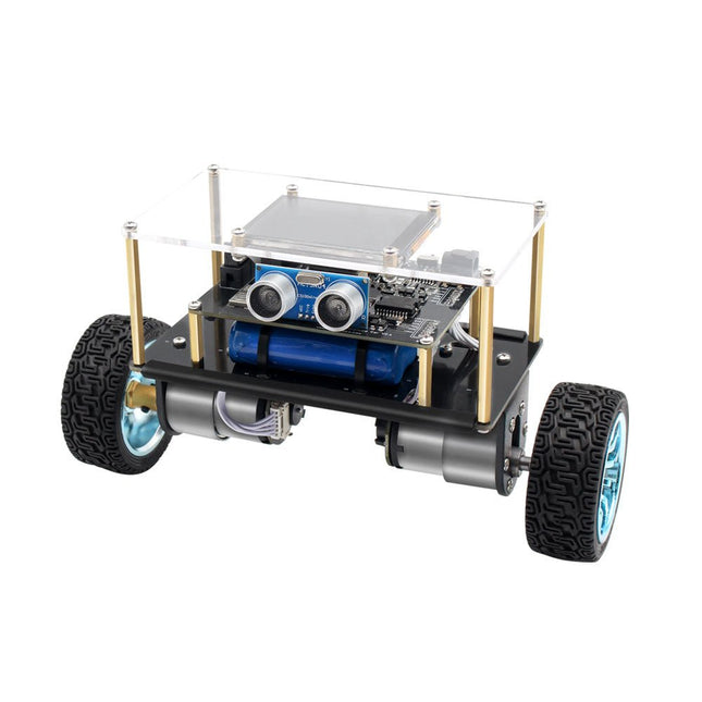
Elektor Labs Elektor Mini-Wheelie zelfbalancerende Robot
Arduino-compatibele, ESP32-aangedreven tweewielige balansrobot De Elektor Mini-Wheelie is een experimenteel autonoom zelfbalancerend robotplatform. De zelfbalancerende robot is gebaseerd op een ESP32-S3-microcontroller en is volledig programmeerbaar met behulp van de Arduino-omgeving en open-sourcebibliotheken. Dankzij de draadloze mogelijkheden kan hij op afstand worden bediend via Wi-Fi, Bluetooth of ESP-NOW, of kan hij communiceren met een gebruiker of zelfs een andere robot. Er is een ultrasone transducer beschikbaar voor het detecteren van obstakels. Het kleurendisplay kan worden gebruikt voor het weergeven van schattige gezichtsuitdrukkingen of, voor de meer nuchtere gebruikers, voor cryptische debug-berichten. De robot wordt geleverd als een compleet bouwpakket met onderdelen die u zelf in elkaar moet zetten. Alles zit erbij, zelfs een schroevendraaier. Let op: De Mini-Wheelie is een educatief ontwikkelingsplatform bedoeld voor leren, experimenteren en robotica-ontwikkeling. Het is niet geclassificeerd als speelgoed voor kinderen en de functies, documentatie en beoogde doelgroep weerspiegelen dit doel. Het product is gericht op studenten, docenten en ontwikkelaars die robotica, programmeren en hardware-integratie willen verkennen in een educatieve omgeving. Specificaties ESP32-S3-microcontroller met Wi-Fi en Bluetooth MPU6050 6-assige Inertial Measurement Unit (IMU) Twee onafhankelijk geregelde 12 V elektromotoren met toerenteller Ultrasone transducer 2,9" TFT-kleurendisplay (320 x 240) MicroSD-kaartsleuf Batterijstroommonitor 3S oplaadbare Li-Po-batterij (11,1 V/2200 mAh) Batterijlader meegeleverd Op Arduino gebaseerde open source-software Afmetingen (B x L x H): 23 x 8 x 13 cm Inbegrepen 1x ESP32-S3 Mainboard + MPU6050 module 1x LCD-board (2,9 inch) 1x Ultrasone-sensor 1x Batterijpakket (2200 mAh) 1x Batterijlader 1x Motorbandenset 1x Kastboard 1x Acrylplaat 1x Schroevendraaier 1x Beschermstrip 1x Flexkabel B (8 cm) 1x Flexkabel A (12 cm) 1x Flexkabel C 4x Koperen kolom A (25 mm) 4x Koperen kolom B (55 mm) 4x Koperen kolom C (5 mm) 2x Kunststof nylon zuil 8x Schroeven A (10 mm) 24x Schroeven B (M3x5) 8x Moeren 24x Metalen ringen 2x Ritssluiting 1x MicroSD-kaart (32 GB) Downloads Documentation
€ 99,95€ 79,95Beste prijs


