
Zoekresultaten voor "io OR warrior56 OR module OR 130006 OR 91"
-
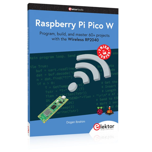
Elektor Publishing Raspberry Pi Pico W (Book)
Program, build, and master 60+ projects with the Wireless RP2040 The Raspberry Pi Pico and Pico W are based on the fast, efficient, and low-cost dual-core ARM Cortex M0+ RP2040 microcontroller chip running at up to 133 MHz and sporting 264 KB of SRAM and 2 MB of Flash memory. Besides spacious memory, the Pico and Pico W offer many GPIO pins, and popular peripheral interface modules like ADC, SPI, I²C, UART, PWM, timing modules, a hardware debug interface, and an internal temperature sensor. The Raspberry Pi Pico W additionally includes an on-board Infineon CYW43439 Bluetooth and Wi-Fi chipset. At the time of writing this book, the Bluetooth firmware was not yet available. Wi-Fi is however fully supported at 2.4 GHz using the 802.11b/g/n protocols. This book is an introduction to using the Raspberry Pi Pico W in conjunction with the MicroPython programming language. The Thonny development environment (IDE) is used in all of the 60+ working and tested projects covering the following topics: Installing the MicroPython on Raspberry Pi Pico using a Raspberry Pi or a PC Timer interrupts and external interrupts Analogue-to-digital converter (ADC) projects Using the internal temperature sensor and external sensor chips Using the internal temperature sensor and external temperature sensor chips Datalogging projects PWM, UART, I²C, and SPI projects Using Bluetooth, WiFi, and apps to communicate with smartphones Digital-to-analogue converter (DAC) projects All projects are tried & tested. They can be implemented on both the Raspberry Pi Pico and Raspberry Pi Pico W, although the Wi-Fi-based subjects will run on the Pico W only. Basic programming and electronics experience are required to follow the projects. Brief descriptions, block diagrams, detailed circuit diagrams, and full MicroPython program listings are given for all projects.
€ 44,95
Beste prijs
-

Elektor Digital PIO-Programmierung mit dem Raspberry Pi Pico (PDF)
Praxisnahe Projekte, Profi-Tricks und eigene Anwendungen Dieses Buch führt Sie Schritt für Schritt in die faszinierende Welt der State Machines ein und zeigt, wie Sie Hardware direkt und effizient ansteuern können – jenseits klassischer CPU-gesteuerter Ansätze. In diesem Buch lernen Sie: LEDs und NeoPixel kreativ steuern: Blinken, Dimmen, Farbwechsel und komplexe Animationen Taster und Encoder zuverlässig auslesen und in Echtzeit in Ihre Projekte integrieren Analoge Eingänge (ADC) nutzen und Signale digital steuern Servos präzise ansteuern und Bewegungsabläufe automatisieren SPI mit PIO umsetzen, um Displays, Sensoren und Module anzusteuern Menüsysteme und Submenüs auf SPI-Displays realisieren, inklusive Navigation über mehrere Taster PWM, Signalgenerierung und Frequenzsteuerung für akustische oder visuelle Effekte Debugging-Strategien und Tipps, um Ihre PIO-Programme effizient zu entwickeln Alle Beispiele sind praxisnah, sofort umsetzbar und zuverlässig. Mit klaren Anleitungen, Hintergrundwissen und fertigen Codebeispielen lernen Sie, die PIO-Fähigkeiten des Pico maximal zu nutzen – egal ob für Maker-Projekte, Prototypen oder professionelle Anwendungen. Erleben Sie, wie Sie komplexe Hardwaresteuerung elegant mit dem Pico realisieren können – schneller, flexibler und leistungsfähiger als je zuvor.
€ 29,80
Leden: € 26,82
-

Elektor Digital Elektor Septembre/Octobre 2024 (PDF)
Le téléchargement intégral de ce numéro est disponible pour nos membres GOLD et GREEN sur le site Elektor Magazine ! Pas encore membre ? Cliquez ici. un nœud de capteurs autonometransmission de données basée sur LoRa et alimentation en énergie par cellules solaires la carte eXpansion V1.0 d'Elektorpour ESP32S3 et autres cartes XIAO une caméra dans un train miniatureinstallation d’un module ESP32 CAM antenne magnétique à large bande pour les grandes ondestous les émetteurs sans aucun accord TensorFlow Lite pour microcontrôleurspar un débutant, pour les débutants un concentrateur pour les appareils RS-422 et RS-485câbler votre bus comme une star sonde RFWith LED Bar Graph démarrer en électronique...…plus de montages à ampli-op Open Variovariomètre multifonction open source pour vol en parapente sur le vifÀ propos de prendre les choses pour acquises relevé des compteurs d'eau basé sur l'IA (Partie 2)intégrez votre ancien compteur dans l'IdO ! agriculture intelligentedétection des nuisibles basée sur l’apprentissage machine avec connectivité IdO Anybus CompactCom est le choix idéal pour la communication industrielle embarquée – voici pourquoi norme de communication IQRFfiabilité des réseaux maillés sans fil à faible débit avec perte comment construire un robot agricole intelligentquelles sont les considérations essentielles que les concepteurs de robots agricoles doivent prendre en compte et à quels défis techniques sont-ils confrontés ? filtre coupe-bande audio à fréquence réglablesolution universelle de suppression de fréquences dans le domaine audio le système LeoINAGPSsurveillez votre véhicule électrique nœud LoRa alimenté par énergie solaireune solution IdO modulaire, compacte et polyvalente AWS pour Arduino et cie. (2)transmission de données avec AWS IoT ExpressLink projet 2.0corrections, mises à jour et courrier des lecteurs 2024 : l'odyssée de l'IAexamen des Accélérateurs IA : comparaison extension de couverture Wi-Fi sur ESP32comment modifier simplement une antenne
€ 10,95
-

Elektor Labs Elektor Low-noise Labvoeding
De low-noise labvoeding van Elektor is een volledig analoge, instelbare, symmetrische unit met gemiddeld vermogen, zonder schakelende of digitale componenten. De uitgangsspanning is instelbaar tussen 0 V en ±22 V, en de uitgangsstroom kan worden ingesteld van 0 A tot 1 A. Doordat elke vorm van schakeltechniek wordt vermeden, levert het ontwerp extreem weinig ruis. Voor de weergave van beide uitgangsspanningen en -stromen worden vier kleine analoge paneelmeters met draaispoel gebruikt. De meeste moderne laboratoriumvoedingen en AC-adapters maken gebruik van schakelende technieken. Zelfs de beste uitvoeringen vertonen onvermijdelijk hoogfrequente rimpel en andere schakelartefacten op hun uitgang, die het testen van gevoelige analoge schakelingen kunnen verstoren en metingen van kleine signalen kunnen beïnvloeden. Om dit te voorkomen, is het concept hier een volledig analoge voeding. Hoewel deze minder efficiënt is dan vergelijkbare schakelende voedingen, is de lagere efficiëntie bij gebruik op de testbank nauwelijks van belang en zorgt deze voor schonere en betrouwbaardere meetresultaten. Omdat veel analoge schakelingen een symmetrische voeding vereisen, levert dit ontwerp positieve en negatieve uitgangsspanningen van gelijke grootte. Een kleine hoeveelheid afregeling is beschikbaar om eventuele onbalans te compenseren. Uiteraard is ook een instelbare stroombegrenzing aanwezig. De kit bevat de onderdelen die nodig zijn om de voeding te bouwen, met uitzondering van de transformatoren. Specificaties Uitgangsspanning 0…+22 V, 0, −22 V Uitgangsstroom 0…+1 A, 0…−1 A Ruis −85 dBV (bij 0,95 A/20 V, B = 22 kHz) −84 dBV (bij 0,95 A/20 V, B > 500 kHz) Rimpelspanning 50 µVRMS (bij 950 mA/20 V, B = 22 kHz, voornamelijk 100-Hz-component) Inbegrepen 3x printplaten: regelaar (PCB-1), netfilter (PCB-2) en transformator (PCB-3) Alle componenten, behalve de AC-transformatoren 4x draaispoelmeters Extra onderdelen voor de bedrading (draden, banaanstekkerbussen, IEC-voedingsmodule, enz.) Niet inbegrepen De drie AC-transformatoren Een behuizing Onderdelenlijst Voor de regelaar-printplaat (240386-1) Weerstanden (250 mW, 1%) R1 = 12 Ω R2, R8, R37, R62 = 1 MΩ R3, R7, R10, R13, R17, R20, R22, R30, R35, R42, R45, R47, R55, R60 = 100 Ω, 600 mW R4, R5 = 4.7 kΩ R6 = 100 kΩ R9, R12, R14, R36, R38, R39, R61, R63, R66, R72, R78, R79 = 10.0 kΩ, 600 mW R11 = 9.76 kΩ, 600 mW R15, R40 = 44.2 kΩ, 600 mW R16, R41, R77 = 1 kΩ R18, R43 = 1.5 kΩ, 1 W, 5% R19, R44 = 470 Ω, 1 W, 5% R21, R46 = 330 Ω, 600 mW R23, R24, R48, R49 = 1.0 Ω, 1 W R25, R50 = 1 kΩ, 1 W, 5% R26, R28, R51, R53 = 1.000 kΩ 0.1%, 15 ppm/C R27, R29, R52, R54 = 10.00 kΩ 0.1%, 15 ppm/C R31, R56 = 1.2 kΩ, 1 W, 5% R32, R57 = 47 kΩ R33, R58 = 270 Ω R34, R59 = 27 kΩ R64, R69 = 12.0 kΩ R65 = 3.0 kΩ, 600 mW R67, R80 = 470 Ω, 600 mW R68, R70 = 6.8 kΩ, 600 mW R71 = 30.0 kΩ,, 600 mW R73, R74, R75, R76 = 10 MΩ P1, P2, P3 = 10 kΩ, 200 mW, 20%, potentiometer, 1 turns, single, lin., panel mount P4, P5 = 500 Ω, 500 mW, 10%, trimmer, 25 turns, 3296Y-1-501LF Bourns P6, P7 = 10 kΩ, 500 mW, 10%, trimmer, 25 turns, 3296Y-1-501LF Bourns Condensatoren C1 = 100 nF, 50 V, 10%, ceramic X7R, LS 5 mm C2, C3, C6, C7, C30 = 10 µF, 63V, 20%, LS 2.5 mm, 3000hours@105°C C4, C5, C8, C9, C13, C14, C18, C19, C23, C24, C28, C29, C31, C32, C38, C39 = 100 nF, 250 V, 10%, PET, LS 7.5 mm C10, C20 = 47 nF, 100 V, 5%, PET, LS 5 mm C11, C21 = 10 nF, 100 V, 5%, PET, LS 5 mm C12, C22 = 220 µF, 35 V, 20%, 0.024 Ω, LS2.5/3.5 mm, Ir 3.4 A, 2000hours@125°C, polymer C15, C25 = 120 µF, 50 V, 20%, ESR 0.02 Ω, Diam. 10 mm max., LS 5 mm C16, C26 = 15 nF, 100 V, 5%, PET, LS 5 mm C17, C27 = 47 nF, 100 V, 5%, PET, LS 5 mm C33, C34 = 22 µF, 50 V, 20%, LS 2 mm, 10000 hours @ 105°C C35, C36, C44, C45 = 1 µF, 100 V, 10%, LS 5 mm, ceramic X7R C37 = 100 uF, 50 V, 20%. LS 3.5 mm C40, C41, C42, C43, C46, C47, C48, C49 = 1000 µF, 50 V, 20%, LS 5/7.5 mm, Ir 3.32 A, 10000hours@105°C, D 16 mm C50, C51, C52, C53 = 47 nF, 100 V, 10%, ceramic X7R, LS 5 mm Spoelen L1, L2 = 4.7 µH, 3.2 A, 0.033 Ω, LS 5 mm, RLB0914-4R7ML Bourns L3 = Commom mode choke, 14.5 mH, 3 A, SSRH24NH-30145 Kemet Halfgeleiders D1, D2, D3, D4, D5, D9, D10, D11, D15 = BAT85, DO-34 D6, D7, D12, D13 = SR560, DO-201AD D8, D14, D16 = 1N4148, DO-35 D17 = Zenerdiode, 5.6 V, 0.5 W, DO-41 D18, D19 = 1N4004, DO-41 D20, D21 D22, D23 = V30100CI-M3/P, dual common cathode, TO-220 D24 = Zener diode, 30 V, 1 W, DO-41 LED1, LED2 = LED, red, T-1 (3 mm) LED3, LED4 = LED, green, T-1 (3 mm) TVS1, TVS2 = BZW50-33B, R6 T1, T2, T4 = BC337.25, TO-92 T3 = NJW0302G, TO-3P T5, T6, T8 = BC327.25, TO-92 T7 = NJW0281G, TO-3P T9 = BD139, TO-126 (SOT-32) IC1 = LM334Z, TO-92 IC2 = LM4040AIZ-5.0/NOPB, TO-92 (TO-226AA-3) IC3, IC4 = OPA2992IDR, SOIC-8 IC5, IC6 = OPA4992IDR, SOIC-14 IC7 = OPA992IDBVR, SOT-23-5 IC8 = LM339N, DIP-14 IC9 = LM317, TO-220 IC10 = LM337, TO-220 Overige F1, F2 = 5×20 mm fuse, 1.6 A, fast acting HS1, HS2 = Heatsink MC33271 (for T3/T7), 2.7°C/W, PCB mount, height 63.5 mm K1, K4 = 3-way screw terminal block, LS 3.5 mm, max. 1.5 mm² K2, K3 = 3-way screw terminal block, LS 3.5 mm, max. 1 mm² M1, M3 = Moving coil meter, Range 30 V, type 91C4, 45×45 mm M2, M4 = Moving coil meter, Range 1 A, type 91C4, 45×45 mm² RE1 = Relay DPDT,5V, UA2-5NU Diversen 3× 3-way screw terminal block, LS 3.5 mm, max. 1 mm² (for P1, P2, P3) 4× Pin header, 1×2, vertical, pitch 2.54 mm (for LED1, LED2, LED3, LED4) 4× Pin socket, 1×2, vertical. pitch 2.54 mm (for LED1, LED2, LED3, LED4) 2× Heatsink FK222SA220, 20°C/W, PCB mount (for IC9 & IC10) 2× Mica thermal pad for TO-220, 12×18×0.05 mm (for IC9 & IC10) 2× Insulating bushing IB 6, TO-220 (for IC9 & IC10) 2× Ceramic thermal pad, 23×20×2 mm (for T3 & T7) 2× PCB Fuse Holder, for 5×20 mm fuse, 10 A (for F1, F2) 2× Cover for PCB Fuse Holder, transparent (for F1, F2) 2× 2-way screw terminal block, LS 3.5 mm, max. 1 mm² (for M1 & M3) 2× 2-way screw terminal block, LS 3.5 mm, max. 1.5 mm² (for M2 & M4) 8× M3 solder lug, thickness 0.35 mm (for M1…M4) M4 solder lug, thickness 0.35 mm (to connect 4 mm banana connectors) Screened cable, 1 pair, 2×24 AWG/0.22 mm², 1 m (for P1, P2 & P3) IC socket, DIP, 14 contacts (for IC8) M3 washer, plain, steel M3 screw, 16 mm, steel, pan head M3 nut M3 spring washer 50 mm M3 standoff, steel, male-female 12 mm M3 standoff, steel, male-female 10 mm M3 standoff, steel, male-female M3 screw, 8 mm, steel, pan head Voor de netfilter-printplaat (240386-2) Weerstand R1 = 220 kΩ, 1 W, 500 V, 5% Condensatoren C1, C2 = 470 nF, 305 VAC, Class X2, 11 × 27 mm max., LS 15/22.5 mm C3, C4, C5, C6 = 2.2 nF, 300 VAC, Class Y2, 13 × 4 mm, LS 10 mm, PP Spoelen L1, L2 = Common-mode choke, 6.8 mH, 1.7 A, TDK B82732R2172B030 Halfgeleider MOV1 = TVS varistor, 300 VAC, S14K300 (230 VAC, B72214S0301K101) and SK14K150 (150 VAC, B72214S0151K101) Overige K1, K2 = 3-way screw terminal block, LS 7.62 mm F1 = Time-delay fuse, 0.5 A (230 VAC) or 1 A (115 VAC) Diversen 1× Fuse holder, 5×20 mm, 10 A, 500 VAC 1× Transparent fuse cover 4× 10 mm M3 standoff, steel, male–female 4× M3 screw, 8 mm, steel, pan head 4× M3 nut Voor de transformator-printplaat (240386-3) Weerstanden R1, R2 = 2.7 kΩ, 600 mW, 1% R3 = 10.0 kΩ, 600 mW, 1% Condensator C1 = 220 µF, 50 V, 20%, Ø10 mm, LS 5 mm, 4000 h @ 105°C Transformatoren (niet inbegrepen in deze kit!) TR1, TR2, TR3 = 2×7 V, 25 VA, PCB-mounted toroid, 70060K Talema Halfgeleiders D1–D4 = 1N4148, DO-35 D5, D6 = 1N4004, DO-41 D7 = Zener 5.6 V, 1.3 W, DO-41 LED1 = LED, red, T-1 (3 mm) IC1, IC2 = MOC8021M, CTR ≥ 1000%, DIP-6 Overige F1, F2, F3 = 160 mA time-delay fuse (230 VAC) or 315 mA time-delay fuse (115 VAC) K1 = 2-way screw terminal block, LS 7.62 mm K2 = 3-way screw terminal block, LS 3.5 mm, max 1.5 mm² K3, K4 = 3-way screw terminal block, LS 3.5 mm, max 1 mm² RE1, RE2 = Relay DPDT, 5 A/250 VAC / 24 VDC Diversen 1× Pin header 1×2, pitch 2.54 mm + matching socket for LED1 3× Fuse holder 5 × 20 mm, 10 A, 500 VAC + transparent cover 3× M4 screw, 8 mm, pan head + washer for TR1-TR3 8× M3 screw, 8 mm, pan head + nut + washer 8× 10 mm M3 standoff, steel, male–female 2× IC socket, DIP-6 for IC1 & IC2 Extra onderdelen 1 m red insulated wire, stranded, 1.5 mm² 0.5 m blue insulated wire, stranded, 1.5 mm² 0.5 m black insulated wire, stranded, 1.5 mm², 0.5 m 2 m red insulated wire, stranded, D 0.56 mm (0.25 mm²) 2 m black insulated wire, stranded, D 0.56 mm (0.25 mm²) 0.5 m Multicore Cable, Flexible, 3 Core, 0.75 mm² (24 x 0.2 mm) Red banana socket Black banana socket Blue banana socket Green banana socket IEC Power Entry Module with switch, IEC C14 3 crimp terminals, FASTON, 4.75 x 0.81 mm 3 knobs Links Elektor Labs JumpStarter Page Artikel (deel 1) Artikel (deel 2)
€ 249,00
Beste prijs
-
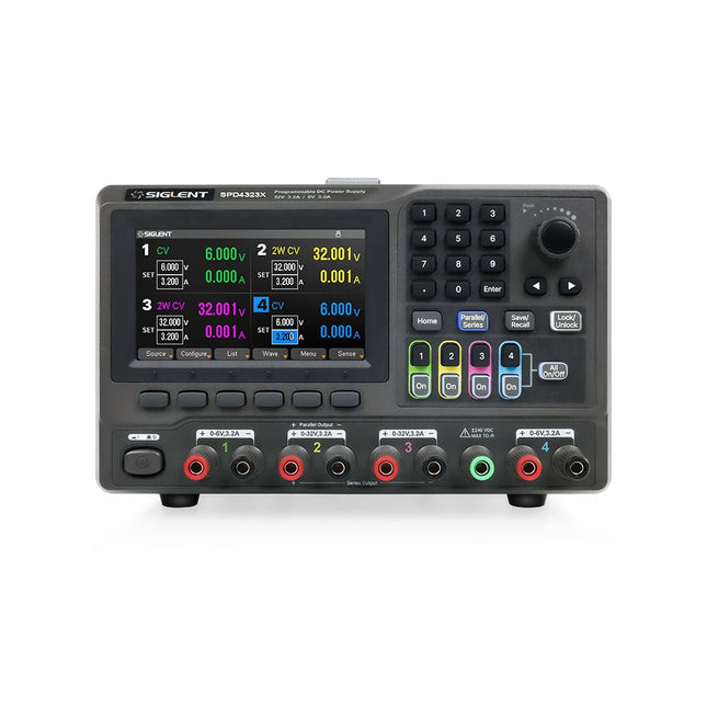
Siglent Siglent SPD4323X 4-kanaals Voeding (240 W)
The Siglent SPD4323X is a 4-channel DC Linear Programmable Power Supply equipped with a 4.3-inch TFT-LCD display, friendly human-machine interface, and excellent performance indicators. Real-time waveform display provides engineers with an informative user interface. SPD4323X offers a total output power of 240 W with a resolution of 1 mV/1 mA. The maximum voltage and current for each channel are as follows: CH1: 6 V/3.2 A CH2: 32 V/3.2 A CH3: 32 V/3.2 A CH4: 6 V/3.2 A Kenmerken Rated output power: 240 W Rated voltage: 32 V, 12 V, 30 V Up to four high-precision power supplies with independent controllable outputs, supporting CH2 and CH3 series and parallel connections Clear graphical interface with waveform and timer display modes 5-digit voltage and current display with minimum resolution of 1 mV, 1 mA Fast output response time: <50us The high current channel support remote voltage compensation sense function. The maximum compensation voltage is 0.6 V Overvoltage protection and overcurrent protection or safe and accurate operation Equipped with a 4.3-inch TFT-LCD display (480 x 272 resolution) USB and LAN standard communication USB-GPIB module is optional Excellent channel density with up to 4 channels in a 3U half rack package Internal data storage for setups and parameters Embedded Web Server with instrument communication that doesn’t require software installation Fully SCPI programming command set support as well as a LabView driver for remote control and system automation Specificaties SPD4323X SPD4121X SPD4306X Channel Output CH1: Voltage 0 to 6 V Current 0 to 3.2 ACH2: Voltage 0 to 32 V Current 0 to 3.2 ACH3: Voltage 0 to 32 V Current 0 to 3.2 ACH4: Voltage 0 to 6 V Current 0 to 3.2 A CH1: Voltage 0 to 15 V Current 0 to 1.5 ACH2: Voltage 0 to 12 V Current 0 to 10 ACH3: Voltage 0 to 12 V Current 0 to 10 ACH4: Voltage 0 to 15 V Current 0 to 1.5 A CH1: Voltage 0 to 15 V Current 0 to 1.5 ACH2: Voltage 0 to 30 V Current 0 to 6 ACH3: Voltage 0 to 30 V Current 0 to 6 ACH4: Voltage 0 to 15 V Current 0 to 1 A Resolution 1 mV, 1 mA 1 mV, 1 mA 1 mV, 1 mA Setting Accuracy Voltage: ±(0.03% of reading+10) mV, Current: ±(0.3% of reading+10) mA Voltage: ±(0.03% of reading+10) mV, Current: ±(0.3% of reading+10) mA Voltage: ±(0.03% of reading+10) mV, Current: ±(0.3% of reading+10) mA Readback Accuracy Voltage: ±(0.03% of reading+10) mV, Current: ±(0.3% of reading+10) mA Voltage: ±(0.03% of reading+10) mV, Current: ±(0.3% of reading+10) mA Voltage: ±(0.03% of reading+10) mV, Current: ±(0.3% of reading+10) mA Display 4.3" TFT-LCD 5-digit voltage and current display 4.3" TFT-LCD 5-digit voltage and current display 4.3" TFT-LCD 5-digit voltage and current display Output power 240 W 285 W 400 W Inbegrepen 1x Siglent SPD4323X Power Supply 1x Power cord (EU) 1x Output test cord (3 A) 1x USB cable 1x Quick start guide Downloads Datasheet Manual Quick start
€ 762,30
-

Rigol Rigol DG2102 Function/Arbitrary Waveform Generator (100 MHz)
Highlights Output Frequency (Sine): 100 MHz Output Frequency (Square): 25 MHz Channels: 2 Arbitrary Waveform Length: 16 Mpts Kenmerken Unique SiFi II (Signal Fidelity II) technology: generate the arbitrary waveforms point by point; recover the signal without distortion; sample rate accurate and adjustable; jitter of all the output waveforms (including Sine, Pulse, etc.) as low as 200 ps 16 Mpts memory depth per channel for arbitrary waveforms Standard dual-channel with the same performance, equivalent to two independent signal sources High frequency stability: ±1 ppm; low phase noise: -105 dBc/Hz Built-in high-order harmonic generator (at most 8-order harmonics) Built-in 7 digits/s, 240 MHz bandwidth full featured frequency counter Up to 160 built-in arbitrary waveforms, covering the common signals in engineering application, medical electronics, auto electronics, math processing, and other various fields Sample rate up to 250 MSa/s, vertical resolution 16 bits Arbitrary waveform sequence editing function available; arbitrary waveforms also can be generated through the PC software Various analog and digital modulation functions: AM, FM, PM, ASK, FSK, PSK, and PWM. Standard waveform combine function, capable of outputting specified waveforms combined with the basic waveforms Standard channel tracking function, when enabled, all the parameters of both channels are updated based on users' configurations Standard interface: USB Host&Device and LAN (LXI Core 2011 Device); USB-GPIB function supported 4.3'' TFT Inbegrepen 1x Rigol DG2102 Function/Arbitrary Waveform Generator 1x Power cord 1x USB cable
€ 1.087,79
-

OWON OWON DGE3062 2-kanaals Arbitraire Golfvormgenerator (60 MHz)
The OWON DGE3062 is a 14-bit function generator with a bandwidth of 60 MHz. It has 5 basic waveforms, 160 built-in arbitrary waveforms and the following comprehensive modulation functions: AM, FM, PM, PWM, FSK, 3FSK, 4FSK, PSK, ASK, BPSK, OSK, DSBAM, QPSK, SUM, sweep, Burst. Kenmerken Max. 60 MHz frequency output, 300 MSa/s Sample rate 14 bits Vertical Resolution, 100K Arb waveform length Comprehensive waveform output: 5 basic waveforms, and 160 built-in arbitrary waveforms Comprehensive modulation functions: AM, FM, PM, PWM, FSK, 3FSK, 4FSK, PSK, ASK, BPSK, OSK, DSBAM, QPSK, SUM, sweep, Burst SCPI and LabVIEW supported 3.6 inch LCD (480 x 272 pixels) Specificaties Channel 2 Frequency Output 60 MHz Sample Rate 300 MSa/s Vertical Resolution 14 bits Waveform Standard Waveform Sine, square, pulse, ramp, noise Arbitrary Waveform Exponential rise, exponential fall, sin(x)/x, step wave, and others, total 160 built-in waveforms Frequency (resolution 1 μHz) Sine 1 μHz-60 MHz Square 1 μHz ~ 20 MHz Pulse 1 μHz ~ 20 MHz Ramp 1 μHz ~ 2 MHz Noise 20 MHz (-3 dB, typical) Arbitrary Waveform 1 μHz ~10 MHz Arbitrary Waveform Length 2 points – 100K points Sample Rate 300 MSa/s Amplitude Into 50Ω load 1mVpp ~ 10Vpp (≤10Hz), 1mVpp ~ 5Vpp (≤60 MHz) DC Offset Range (AD+DC ±(10 Vpk – Amplitude Vpp/2) high resistance±(5 Vpk – Amplitude Vpp/2) 50 Ω DC offset resolution 1 mV or 4 digits Load Impedance 50 Ω (typical) DC offset Accuracy ±(1% of |setting| + 1 mV + amplitude Vpp * 0.5%) Modulation Type AM,FM, PM, PWM, FSK, 3FSK, 4FSK, PSK, ASK, BPSK, OSK, DSB-AM, QPSK, SUM, Sweep, Burst Frequency Counter Function Frequency, period Frequency Range 100 MHz ~ 100 MHz Frequency Resolution 6 digits Input/Output Display 3.6” LCD Input mode External modulation input, external trigger input, external reference clock input/output Communication Interface USB Host, USB Device Mechanical specifications Dimensions (W x H x D) 200 x 92 x 157 mm Weight 0.8 kg Inbegrepen 1x OWÒN DGE3062 Arbitraire Golfvormgenerator 1x Power Cord 1x Quick Guide 1x USB Cable 1x Q9 Cable 1x BNC to Alligator Clip Downloads Quick Guide Manual Software
€ 212,50
-
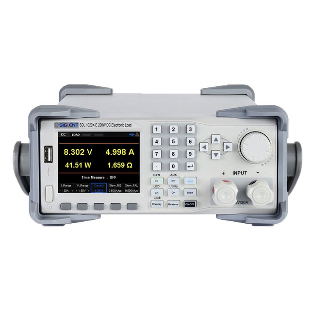
Siglent Siglent SDL1020X-E DC Electronic Load (200 W)
De Siglent SDL1020X-E DC meetsnoeren hebben een meetresolutie van 0,1 mV/0,1 mA en de basis SDL1000X-E serie heeft een resolutie van 1 mV/1 mA en instelbare stroom flankstijgtijden van 0,001 A/?s~2,5 A/?s. Voor communicatie en bediening op afstand bevat de SDL serie S232/USB/LAN interfaces. De SDL1020X-E levert stabiliteit over een breed scala van toepassingen en kan aan allerlei test vereisten voldoen. o.a: Voeding, batterij/handapparaat ontwerp, industrie, LED verlichting, auto-elektronica, en ruimtevaart. Kenmerken SDL1020X-E (één kanaal): DC 150 V/30 A, totaal vermogen 200 W 4 Statische modes / Dynamische mode: CC/CV/CR/CP CC Dynamische stand: Continu, gepulseerd, omgeschakeld CC Dynamische stand: 25 kHz, CP Dynamische stand: 12,5 kHz, CV Dynamische modus: 0,5 Hz Meetsnelheid van spanning en stroom: tot 500 kHz Instelbaar bereik van de stijgtijd van de stroom: 0,001 A/us~2,5 A/us Min. afleesresolutie: 0,1 mV, 0,1 mA Kortsluit-, batterijtest-, CR-LED modus-, en fabriekstestfuncties 4-draads SENSE compensatie mode functie List functie ondersteunt het bewerken van wel 100 stappen Programmeerfunctie ondersteunt 50 groepen stappen OCP, OVP, OPP, OTP en LRV beveiliging Externe analoge regeling Spanning, stroom bewaking via 0-10 V 3,5 inch TFT-LCD scherm, geschikt voor gelijktijdige weergave van meerdere parameters en toestanden Ingebouwde RS232/USB/LAN communicatie interface, USB-GPIB module (optioneel) Trendgrafiek van golfvormen en gemakkelijk te gebruiken functies voor het opslaan en oproepen van bestanden Inclusief PC software: Ondersteunt SCPI, LabView aandrijving Inbegrepen 1x Siglent SDL1020X-E DC programmeerbare belasting 1x Snelstartgids 1x Garantiekaart 1x Netsnoer 1x USB kabel Downloads Datasheet Manual Programming Guide PC Software
€ 531,19
-

Elektor Digital Elektor Special: Stromversorgung & Batterien (PDF)
Der simpel „Stromversorgung“ genannte Schaltungsteil wird sowohl bei der Entwicklung als auch bei der Reparatur von Elektronik enorm unterschätzt. Dabei ist die Vielfalt bei Netzteilen oder neudeutsch „PSU“ enorm. Es gibt sie in den unterschiedlichsten Ausführungen: mit Gleich- oder Wechselspannung, als Generator, Akku oder Batterie, als Solar-Panel, extern oder eingebaut, linear oder „geschaltet“ – um nur einige zu nennen. Auch die Leistungsbereiche sind enorm: von Nano-Ampere bis Kilo-Ampere – dasselbe gilt für Spannungen. Bei der konkreten Umsetzung kann man zwischen ICs oder diskreten Bauteilen, zwischen fertigem Gerät bzw. Modul oder der Realisation aus selbstverlöteten Bauteilen wählen. Dieses Special deckt die wichtigsten Merkmale und Gestaltungsaspekte von Stromversorgungen ab. Inhalt Grundlagen BatteriemanagementWas man beim Einsatz von (Lithium-)Akkus beachten muss. Festspannungsnetzgerät mit LinearreglerDas beste Ergebnis gleich nach den Batterien. Lichtenergie sammelnWie man ein Solarmodul für ein Energy-Harvesting-Projekt verwenden kann. Netzbetriebene VersorgungsgeräteBasis-schaltungen und Tipps für Transformatoren, Gleichrichtung, Siebung und Stabilisierung. SanftanlaufDer hohe Einschaltstrompuls sollte vermieden werden. Steuerbare GleichrichterEinige Vorschläge um die Verlustleistung im Längsregler möglichst gering zu halten. Komponenten Arbeitsblatt: Spannungsreglerserie LM117 / LM217 / LM317 Supercaps Reviews Labornetzteil-Kit Joy-iT RD6006 Elektronische Last Siglent SDL1020X-E Projekte Balkon-KraftwerkSelbst installiert = schnell amortisiert! DIY-LiPo-Supercharger-KitVom Prototyp zum Massenmarkt. Doppelanoden-MOSFET-ThyristorSchneller und effizienter als herkömmliche SCRs. Batterie-EntsafterNicht wegwerfen, ausquetschen! Hochspannungsnetzteil mit KennlinienschreiberSpannungen bis 400 V einstellen und Kennlinien für Röhren und Transistoren erstellen. HochspannungsnetzteilFür RIAA-Röhrenvorverstärker und andere Anwendungen. MicroSupplyEine Laborstromversorgung für universelle Anwendungen. Phantom-Speisung mit geschalteten KondensatorenSpannungsverdreifachung mit zwei ICs. Das SMPS800RE Schaltnetzteil für den Elektor Fortissimo-100Zuverlässig, leicht und erschwinglich. SoftstartSchont das Netzgerät und die Last. UniLab 2Geschaltetes Labornetzteil 0…30 V/3 A Tipps Softstart für Step-Down-Schaltregler Stromabschaltung mit minimalen Verlusten Powerbank-Geheimnisse Künstliche Masse Akku-Erfrischer Akkupack-Entlader Parallelschaltung von Spannungsreglern
€ 11,90
Leden: € 10,71
-

Elektor Publishing The BeagleY-AI Handbook
A Practical Guide to AI, Python, and Hardware Projects Welcome to your BeagleY-AI journey! This compact, powerful, and affordable single-board computer is perfect for developers and hobbyists. With its dedicated 4 TOPS AI co-processor and a 1.4 GHz Quad-core Cortex-A53 CPU, the BeagleY-AI is equipped to handle both AI applications and real-time I/O tasks. Powered by the Texas Instruments AM67A processor, it offers DSPs, a 3D graphics unit, and video accelerators. Inside this handbook, you‘ll find over 50 hands-on projects that cover a wide range of topics—from basic circuits with LEDs and sensors to an AI-driven project. Each project is written in Python 3 and includes detailed explanations and full program listings to guide you. Whether you‘re a beginner or more advanced, you can follow these projects as they are or modify them to fit your own creative ideas. Here’s a glimpse of some exciting projects included in this handbook: Morse Code Exerciser with LED or BuzzerType a message and watch it come to life as an LED or buzzer translates your text into Morse code. Ultrasonic Distance MeasurementUse an ultrasonic sensor to measure distances and display the result in real time. Environmental Data Display & VisualizationCollect temperature, pressure, and humidity readings from the BME280 sensor, and display or plot them on a graphical interface. SPI – Voltmeter with ADCLearn how to measure voltage using an external ADC and display the results on your BeagleY-AI. GPS Coordinates DisplayTrack your location with a GPS module and view geographic coordinates on your screen. BeagleY-AI and Raspberry Pi 4 CommunicationDiscover how to make your BeagleY-AI and Raspberry Pi communicate over a serial link and exchange data. AI-Driven Object Detection with TensorFlow LiteSet up and run an object detection model using TensorFlow Lite on the BeagleY-AI platform, with complete hardware and software details provided.
€ 44,95
Leden: € 40,46
-

Elektor Digital Mikrocontroller-Module (PDF)
Mikrocontroller-Module (E-book)
€ 32,80
Leden: € 29,52
-

Elektor Mars/Avril 2026 (FR)
Le téléchargement intégral de ce numéro est disponible pour nos membres GOLD et GREEN sur le site Elektor Magazine ! Pas encore membre ? Cliquez ici. programmation PIO sur le Raspberry Pi PicoNeuf instructions, de multiples possibilités l'IA en ligne de commandeDéveloppement, compilation et validation de projets embarqués depuis le terminal le Scrutiny DebuggerDéboguer, visualiser et tester du code C/C++ embarqué carte breakout Sigfox (1)Développement d’une BoB radio alimentation à faible bruit (2)Construction, assemblage et mise en œuvre pratique générateur de signaux simple basé sur le RP2040Signaux analogiques et numériques à la découverte du futur de la domotique avec Matter et l’IA EdgeLes dernières versions de Matter et l’essor de l’IA en périphérie de réseau (edge) donnent-ils enfin aux ingénieurs les outils nécessaires pour construire les maisons intelligentes et parfaitement intégrées promises aux utilisateurs ? capteurs de pression différentielleLa maintenance prédictive appliquée aux systèmes CVC la sécurité dès la conceptionPrincipes d’ingénierie pour limiter les défaillances la sécurité des systèmes embarqués n’est plus une option la CRA et la PQC redéfinissent les priorités de la sécurité embarquéePourquoi même les petites entreprises IoT et industrielles doivent prévoir une mise à niveau embedded world 2026Entretien avec Benedikt Weyerer, directeur d’embedded world prise en main du bus I3CUtilisation de matériel de ST et Microchip le projet BLEnkyPrototypage rapide d’applications Bluetooth Low Energy modulation de largeur d’impulsionDu thermostat tout ou rien à un signal analogique continu filtré audiotroniqueDes circuits audio agréables à l’écoute, à réaliser soi-même sur le vifLisez donc le manuel ! carte émetteur-récepteur audio ESP32 (4)Réglage des horloges et une option filaire 2026 : une odyssée de l’IAConséquences du vibe coding charge CC symétriqueCharge CC symétrique, statique ou dynamique comptage de visages avec MaixCAMUne méthode simple pour estimer la taille d’un public
€ 16,50


