
Zoekresultaten voor "elektor OR us OR style OR siren OR kit"
-

Elektor Labs Elektor Low-noise Labvoeding
De low-noise labvoeding van Elektor is een volledig analoge, instelbare, symmetrische unit met gemiddeld vermogen, zonder schakelende of digitale componenten. De uitgangsspanning is instelbaar tussen 0 V en ±22 V, en de uitgangsstroom kan worden ingesteld van 0 A tot 1 A. Doordat elke vorm van schakeltechniek wordt vermeden, levert het ontwerp extreem weinig ruis. Voor de weergave van beide uitgangsspanningen en -stromen worden vier kleine analoge paneelmeters met draaispoel gebruikt. De meeste moderne laboratoriumvoedingen en AC-adapters maken gebruik van schakelende technieken. Zelfs de beste uitvoeringen vertonen onvermijdelijk hoogfrequente rimpel en andere schakelartefacten op hun uitgang, die het testen van gevoelige analoge schakelingen kunnen verstoren en metingen van kleine signalen kunnen beïnvloeden. Om dit te voorkomen, is het concept hier een volledig analoge voeding. Hoewel deze minder efficiënt is dan vergelijkbare schakelende voedingen, is de lagere efficiëntie bij gebruik op de testbank nauwelijks van belang en zorgt deze voor schonere en betrouwbaardere meetresultaten. Omdat veel analoge schakelingen een symmetrische voeding vereisen, levert dit ontwerp positieve en negatieve uitgangsspanningen van gelijke grootte. Een kleine hoeveelheid afregeling is beschikbaar om eventuele onbalans te compenseren. Uiteraard is ook een instelbare stroombegrenzing aanwezig. De kit bevat de onderdelen die nodig zijn om de voeding te bouwen, met uitzondering van de transformatoren. Specificaties Uitgangsspanning 0…+22 V, 0, −22 V Uitgangsstroom 0…+1 A, 0…−1 A Ruis −85 dBV (bij 0,95 A/20 V, B = 22 kHz) −84 dBV (bij 0,95 A/20 V, B > 500 kHz) Rimpelspanning 50 µVRMS (bij 950 mA/20 V, B = 22 kHz, voornamelijk 100-Hz-component) Inbegrepen 3x printplaten: regelaar (PCB-1), netfilter (PCB-2) en transformator (PCB-3) Alle componenten, behalve de AC-transformatoren 4x draaispoelmeters Extra onderdelen voor de bedrading (draden, banaanstekkerbussen, IEC-voedingsmodule, enz.) Niet inbegrepen De drie AC-transformatoren Een behuizing Onderdelenlijst Voor de regelaar-printplaat (240386-1) Weerstanden (250 mW, 1%) R1 = 12 Ω R2, R8, R37, R62 = 1 MΩ R3, R7, R10, R13, R17, R20, R22, R30, R35, R42, R45, R47, R55, R60 = 100 Ω, 600 mW R4, R5 = 4.7 kΩ R6 = 100 kΩ R9, R12, R14, R36, R38, R39, R61, R63, R66, R72, R78, R79 = 10.0 kΩ, 600 mW R11 = 9.76 kΩ, 600 mW R15, R40 = 44.2 kΩ, 600 mW R16, R41, R77 = 1 kΩ R18, R43 = 1.5 kΩ, 1 W, 5% R19, R44 = 470 Ω, 1 W, 5% R21, R46 = 330 Ω, 600 mW R23, R24, R48, R49 = 1.0 Ω, 1 W R25, R50 = 1 kΩ, 1 W, 5% R26, R28, R51, R53 = 1.000 kΩ 0.1%, 15 ppm/C R27, R29, R52, R54 = 10.00 kΩ 0.1%, 15 ppm/C R31, R56 = 1.2 kΩ, 1 W, 5% R32, R57 = 47 kΩ R33, R58 = 270 Ω R34, R59 = 27 kΩ R64, R69 = 12.0 kΩ R65 = 3.0 kΩ, 600 mW R67, R80 = 470 Ω, 600 mW R68, R70 = 6.8 kΩ, 600 mW R71 = 30.0 kΩ,, 600 mW R73, R74, R75, R76 = 10 MΩ P1, P2, P3 = 10 kΩ, 200 mW, 20%, potentiometer, 1 turns, single, lin., panel mount P4, P5 = 500 Ω, 500 mW, 10%, trimmer, 25 turns, 3296Y-1-501LF Bourns P6, P7 = 10 kΩ, 500 mW, 10%, trimmer, 25 turns, 3296Y-1-501LF Bourns Condensatoren C1 = 100 nF, 50 V, 10%, ceramic X7R, LS 5 mm C2, C3, C6, C7, C30 = 10 µF, 63V, 20%, LS 2.5 mm, 3000hours@105°C C4, C5, C8, C9, C13, C14, C18, C19, C23, C24, C28, C29, C31, C32, C38, C39 = 100 nF, 250 V, 10%, PET, LS 7.5 mm C10, C20 = 47 nF, 100 V, 5%, PET, LS 5 mm C11, C21 = 10 nF, 100 V, 5%, PET, LS 5 mm C12, C22 = 220 µF, 35 V, 20%, 0.024 Ω, LS2.5/3.5 mm, Ir 3.4 A, 2000hours@125°C, polymer C15, C25 = 120 µF, 50 V, 20%, ESR 0.02 Ω, Diam. 10 mm max., LS 5 mm C16, C26 = 15 nF, 100 V, 5%, PET, LS 5 mm C17, C27 = 47 nF, 100 V, 5%, PET, LS 5 mm C33, C34 = 22 µF, 50 V, 20%, LS 2 mm, 10000 hours @ 105°C C35, C36, C44, C45 = 1 µF, 100 V, 10%, LS 5 mm, ceramic X7R C37 = 100 uF, 50 V, 20%. LS 3.5 mm C40, C41, C42, C43, C46, C47, C48, C49 = 1000 µF, 50 V, 20%, LS 5/7.5 mm, Ir 3.32 A, 10000hours@105°C, D 16 mm C50, C51, C52, C53 = 47 nF, 100 V, 10%, ceramic X7R, LS 5 mm Spoelen L1, L2 = 4.7 µH, 3.2 A, 0.033 Ω, LS 5 mm, RLB0914-4R7ML Bourns L3 = Commom mode choke, 14.5 mH, 3 A, SSRH24NH-30145 Kemet Halfgeleiders D1, D2, D3, D4, D5, D9, D10, D11, D15 = BAT85, DO-34 D6, D7, D12, D13 = SR560, DO-201AD D8, D14, D16 = 1N4148, DO-35 D17 = Zenerdiode, 5.6 V, 0.5 W, DO-41 D18, D19 = 1N4004, DO-41 D20, D21 D22, D23 = V30100CI-M3/P, dual common cathode, TO-220 D24 = Zener diode, 30 V, 1 W, DO-41 LED1, LED2 = LED, red, T-1 (3 mm) LED3, LED4 = LED, green, T-1 (3 mm) TVS1, TVS2 = BZW50-33B, R6 T1, T2, T4 = BC337.25, TO-92 T3 = NJW0302G, TO-3P T5, T6, T8 = BC327.25, TO-92 T7 = NJW0281G, TO-3P T9 = BD139, TO-126 (SOT-32) IC1 = LM334Z, TO-92 IC2 = LM4040AIZ-5.0/NOPB, TO-92 (TO-226AA-3) IC3, IC4 = OPA2992IDR, SOIC-8 IC5, IC6 = OPA4992IDR, SOIC-14 IC7 = OPA992IDBVR, SOT-23-5 IC8 = LM339N, DIP-14 IC9 = LM317, TO-220 IC10 = LM337, TO-220 Overige F1, F2 = 5×20 mm fuse, 1.6 A, fast acting HS1, HS2 = Heatsink MC33271 (for T3/T7), 2.7°C/W, PCB mount, height 63.5 mm K1, K4 = 3-way screw terminal block, LS 3.5 mm, max. 1.5 mm² K2, K3 = 3-way screw terminal block, LS 3.5 mm, max. 1 mm² M1, M3 = Moving coil meter, Range 30 V, type 91C4, 45×45 mm M2, M4 = Moving coil meter, Range 1 A, type 91C4, 45×45 mm² RE1 = Relay DPDT,5V, UA2-5NU Diversen 3× 3-way screw terminal block, LS 3.5 mm, max. 1 mm² (for P1, P2, P3) 4× Pin header, 1×2, vertical, pitch 2.54 mm (for LED1, LED2, LED3, LED4) 4× Pin socket, 1×2, vertical. pitch 2.54 mm (for LED1, LED2, LED3, LED4) 2× Heatsink FK222SA220, 20°C/W, PCB mount (for IC9 & IC10) 2× Mica thermal pad for TO-220, 12×18×0.05 mm (for IC9 & IC10) 2× Insulating bushing IB 6, TO-220 (for IC9 & IC10) 2× Ceramic thermal pad, 23×20×2 mm (for T3 & T7) 2× PCB Fuse Holder, for 5×20 mm fuse, 10 A (for F1, F2) 2× Cover for PCB Fuse Holder, transparent (for F1, F2) 2× 2-way screw terminal block, LS 3.5 mm, max. 1 mm² (for M1 & M3) 2× 2-way screw terminal block, LS 3.5 mm, max. 1.5 mm² (for M2 & M4) 8× M3 solder lug, thickness 0.35 mm (for M1…M4) M4 solder lug, thickness 0.35 mm (to connect 4 mm banana connectors) Screened cable, 1 pair, 2×24 AWG/0.22 mm², 1 m (for P1, P2 & P3) IC socket, DIP, 14 contacts (for IC8) M3 washer, plain, steel M3 screw, 16 mm, steel, pan head M3 nut M3 spring washer 50 mm M3 standoff, steel, male-female 12 mm M3 standoff, steel, male-female 10 mm M3 standoff, steel, male-female M3 screw, 8 mm, steel, pan head Voor de netfilter-printplaat (240386-2) Weerstand R1 = 220 kΩ, 1 W, 500 V, 5% Condensatoren C1, C2 = 470 nF, 305 VAC, Class X2, 11 × 27 mm max., LS 15/22.5 mm C3, C4, C5, C6 = 2.2 nF, 300 VAC, Class Y2, 13 × 4 mm, LS 10 mm, PP Spoelen L1, L2 = Common-mode choke, 6.8 mH, 1.7 A, TDK B82732R2172B030 Halfgeleider MOV1 = TVS varistor, 300 VAC, S14K300 (230 VAC, B72214S0301K101) and SK14K150 (150 VAC, B72214S0151K101) Overige K1, K2 = 3-way screw terminal block, LS 7.62 mm F1 = Time-delay fuse, 0.5 A (230 VAC) or 1 A (115 VAC) Diversen 1× Fuse holder, 5×20 mm, 10 A, 500 VAC 1× Transparent fuse cover 4× 10 mm M3 standoff, steel, male–female 4× M3 screw, 8 mm, steel, pan head 4× M3 nut Voor de transformator-printplaat (240386-3) Weerstanden R1, R2 = 2.7 kΩ, 600 mW, 1% R3 = 10.0 kΩ, 600 mW, 1% Condensator C1 = 220 µF, 50 V, 20%, Ø10 mm, LS 5 mm, 4000 h @ 105°C Transformatoren (niet inbegrepen in deze kit!) TR1, TR2, TR3 = 2×7 V, 25 VA, PCB-mounted toroid, 70060K Talema Halfgeleiders D1–D4 = 1N4148, DO-35 D5, D6 = 1N4004, DO-41 D7 = Zener 5.6 V, 1.3 W, DO-41 LED1 = LED, red, T-1 (3 mm) IC1, IC2 = MOC8021M, CTR ≥ 1000%, DIP-6 Overige F1, F2, F3 = 160 mA time-delay fuse (230 VAC) or 315 mA time-delay fuse (115 VAC) K1 = 2-way screw terminal block, LS 7.62 mm K2 = 3-way screw terminal block, LS 3.5 mm, max 1.5 mm² K3, K4 = 3-way screw terminal block, LS 3.5 mm, max 1 mm² RE1, RE2 = Relay DPDT, 5 A/250 VAC / 24 VDC Diversen 1× Pin header 1×2, pitch 2.54 mm + matching socket for LED1 3× Fuse holder 5 × 20 mm, 10 A, 500 VAC + transparent cover 3× M4 screw, 8 mm, pan head + washer for TR1-TR3 8× M3 screw, 8 mm, pan head + nut + washer 8× 10 mm M3 standoff, steel, male–female 2× IC socket, DIP-6 for IC1 & IC2 Extra onderdelen 1 m red insulated wire, stranded, 1.5 mm² 0.5 m blue insulated wire, stranded, 1.5 mm² 0.5 m black insulated wire, stranded, 1.5 mm², 0.5 m 2 m red insulated wire, stranded, D 0.56 mm (0.25 mm²) 2 m black insulated wire, stranded, D 0.56 mm (0.25 mm²) 0.5 m Multicore Cable, Flexible, 3 Core, 0.75 mm² (24 x 0.2 mm) Red banana socket Black banana socket Blue banana socket Green banana socket IEC Power Entry Module with switch, IEC C14 3 crimp terminals, FASTON, 4.75 x 0.81 mm 3 knobs Links Elektor Labs JumpStarter Page Artikel (deel 1) Artikel (deel 2)
€ 299,00€ 249,00Beste prijs
-

Elektor Digital Build Your Own Software-Defined Radio (E-book)
Practical Guide to Modular RF Design Build Your Own Software-Defined Radio combines RF circuitry with hardware programming and PC-based signal processing. The e-book presents a modular approach to building a complete SDR system using RF Bricks – from the mechanical framework and RF modules to measurement tools, PC software, and FPGA implementations. Practical explanations guide readers through real signal paths, construction steps, and measurement routines, linking hardware and software into a flexible SDR platform. Key topics include: Mechanical setup: RF Brick template, chassis, and 19-inch module carrier Bridges: USB isolator, I²C level shifter, I²C power switch, and practical examples Signal-chain design with RF Bricks: antennas, band filters, NanoVNA work, preamplifiers, PLLs, demodulators, direct-conversion chains, multiband options, and narrowband bricks RF measurement Bricks: single- and dual-tone sources, NPR methods, noise generators, notch filters, broadband amplifiers, and impedance bridges Useful accessories: ATU-100 tuner, X-Phase QRM eliminator, and firmware notes PC host software: SoapyAudio adjustments, GQRX, SDR++, and added functionality GnuRadio elements: control blocks, SSB demodulation, GUI components, messaging, and filter handling FPGA-based SDR: VHDL, toolchains, ADC/DAC blocks, oversampling, and a complete SSB/CW signal chain With its modular structure and detailed working examples, this e-book offers a practical path to building and extending modern SDR systems. Downloads Software
€ 32,95
Leden: € 29,66
-
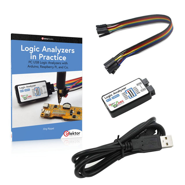
Elektor Bundles Logic Analyzers in Practice (Bundel)
Boek: Logic Analyzers in Practice Step-by-step instructions guide you through the analysis of modern protocols such as I²C, SPI, UART, RS-232, NeoPixel, WS28xx, HD44780 and 1-Wire. With the help of numerous experimental circuits based on the Raspberry Pi Pico, Arduino Uno and the Bus Pirate, you will learn the practical application of popular USB logic analyzers. All the experimental circuits presented in this book have been fully tested and are fully functional. The necessary program listings are included – no special programming or electronics knowledge is required for these circuits. The programming languages used are MicroPython and C along with the development environments Thonny and Arduino IDE. This book uses several models of flexible and widely available USB logic analyzers and shows the strengths and weaknesses of each price range. You will learn about the criteria that matter for your work and be able to find the right device for you. Whether Arduino, Raspberry Pi or Raspberry Pi Pico, the example circuits shown allow you to get started quickly with protocol analysis and can also serve as a basis for your own experiments. After reading this book, you will be familiar with all the important terms and contexts, conduct your own experiments, analyze protocols independently, culminating in a comprehensive knowledge set of digital signals and protocols. USB Logic Analyzer (8-ch, 24 MHz) Deze USB Logic Analyzer is een 8-kanaals logic analyzer met elke ingang bedoeld voor het op twee manieren opnemen van analoge data. Hij is perfect voor het debuggen en analyseren van signalen zoals I²C, UART, SPI, CAN en 1-Wire. De analyzer bemonstert een digitale ingang die is aangesloten op een te testen apparaat (DUT) met een hoge bemonsteringssnelheid. De aansluiting op de PC gaat via USB. Specificaties Kanalen 8 digitale kanalen Maximale bemonsteringssnelheid 24 MHz Maximale ingangsspanning 0 V ~ 5 V Bedrijfstemperatuur 0°C ~ 70°C Ingangsimpedantie 1 MΩ || 10 pF Ondersteunde protocollen I²C, SPI, UART, CAN, 1-wire, enz. PC-aansluiting USB Afmetingen 55 x 28 x 14 mm Downloads Software Deze bundel bevat: Boek "Logic Analyzers in Practice" (normale prijs: € 35) USB Logic Analyzer (8-kanaals, 24 MHz) (normale prijs: € 20) USB-kabel Jumper Draad Lintkabel
€ 54,95€ 44,95Beste prijs
-
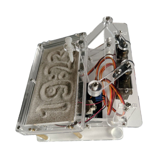
Elektor Labs Elektor Zandklok voor Raspberry Pi Pico
Een op de Raspberry Pi Pico gebaseerde Eye Catcher Een standaard zandklok laat meestal slechts zien hoe de tijd verstrijkt. Deze door een Raspberry Pi Pico aangestuurde zandklok toont daarentegen de exacte tijd door de vier cijfers voor uren en minuten in een zandlaag te "graveren". Na een vooraf ingestelde periode wordt het zand door twee trilmotoren vlak getrild en begint alles weer van voren af aan. Het hart van de zandklok wordt gevormd door twee servomotoren, die via een pantograafmechanisme een schrijfpen aandrijven. Een derde servomotor tilt deze pen op en neer. Het zandbakje is voorzien van twee trilmotoren om het zand weer vlak te trillen. Het elektronische deel van de zandklok bestaat uit een Raspberry Pi Pico en een RTC/driverbord met een real-time klok, plus drivercircuits voor de servomotoren. Een gedetailleerde bouwhandleiding is beschikbaar via download. Kenmerken Afmetingen: 135 x 110 x 80 mm Bouwtijd: ca. 1,5 tot 2 uur Inbegrepen 3x Voorgesneden acrylaatplaten met alle mechanische onderdelen 3x Mini servomotoren 2x Trilmotoren 1x Raspberry Pi Pico 1x RTC/driverkaart met geassembleerde onderdelen Moeren, boutjes, afstandhouders en draden voor de montage Fijnkorrelig wit zand
€ 49,95€ 39,95Beste prijs
-

Elektor Digital Elektor Green Lidmaatschap
Elektronica leren, ontwikkelen en begrijpen – met Elektor Projecten, vakkennis, toegang tot het archief en exclusieve kortingen – alles in één lidmaatschap Wilt u elektronica leren, uw eigen schakelingen ontwikkelen en moderne technologieën beter begrijpen? Elektor Magazine behoort al 65 jaar tot de toonaangevende informatiebronnen voor elektronica-ingenieurs, ontwikkelaars, start-ups en bedrijven. Met een Elektor Green Lidmaatschap verzekert u zich van: ✅ Het internationale elektronica-vakblad Elektor (als digitale uitgave) ✅ Toegang tot het Elektor-archief met 65 jaar elektronica-knowhow ✅ Zelfbouwprojecten, geteste schakelingen, in-depth reviews en tutorials ✅ Exclusieve ledenkortingen op Elektor.nl Waarom Elektor? Al 65 jaar staat Elektor voor gedegen elektronica-kennis, praktijkgerichte projecten en innovatieve technologieën. Van microcontrollers en embedded systemen tot Raspberry Pi, Arduino en ESP32, en van IoT, AI en meettechniek tot audio, RF en robotica: Elektor bestrijkt de belangrijkste platforms en toepassingsgebieden van moderne elektronica. Of u nu beginner, maker of professional bent – met Elektor tilt u uw vaardigheden naar een hoger niveau. Voor wie is het lidmaatschap bedoeld? Beginners – Stap de wereld van de elektronica binnen met begrijpelijke basisprincipes en eerste projecten Makers – Ontdek nieuwe projecten, ideeën en inspiratie voor uw eigen ontwikkelingen Professionals & ingenieurs – Blijf op de hoogte van de nieuwste technologieën en verdiep uw vakkennis Uw voordelen in één oogopslag Tijdschrift (digitaal) – Ontvang elke uitgave digitaal rechtstreeks in uw mailbox 65 jaar kennis van elektronica – Krijg op elk moment toegang tot het uitgebreide Elektor-archief Praktijk & projecten – Breng uw eigen ideeën tot leven met handleidingen, schakelingen en tutorials Exclusieve kortingen – Bespaar bij elke aankoop op Elektor.nl Ontgrendel nu alle Elektor-voordelen! Free Lidmaatschap Green Lidmaatschap ❌ 8× Elektor Magazine (Digitale editie) als PDF ✅ 8× Elektor Magazine (Digitale editie) als PDF ❌ 12 maanden toegang tot het Elektor-archief ✅ 12 maanden toegang tot het Elektor-archief ❌ Toegang tot meer dan 5.000 Gerber-bestanden ✅ Toegang tot meer dan 5.000 Gerber-bestanden ❌ 10% ledenkorting op Elektor.nl ✅ 10% ledenkorting op Elektor.nl ✅ Lees Elektor wekelijks elke vrijdagochtend ✅ Lees Elektor wekelijks elke vrijdagochtend ℹ️ Leest u Elektor liever in gedrukte vorm? Hier vindt u alles over het Elektor Gold-lidmaatschap (print).
€ 89,95 - € 169,95
-

Elektor Labs Elektor Arduino Nano MCCAB Training Board
Het Elektor Arduino Nano MCCAB Training Board bevat alle componenten (incl. Arduino Nano) die nodig zijn voor de oefeningen, zoals LED’s, schakelaars, drukknoppen, buzzer enz. Ook externe sensoren, motoren of modules kunnen worden gecheckt of bestuurd met dit microcontroller-trainingssysteem. Specificaties (Arduino Nano Training Board MCCAB) Voeding Via de USB-aansluiting van de aangesloten pc of een externe voeding (niet inbegrepen) Spanning +5 Vcc Ingangsspanning Alle ingangen 0 V tot +5 V VX1 en VX2 +8 V tot +12 V (alleen bij gebruik van een externe voeding) Hardware LCD 2x16 karakters Potentiometer P1 & P2 JP3: Selectie van de werkspanning van P1 & P2 Verdelers SV4: Verdeler voor de werkspanningenSV5, SV6: Verdelers voor de in-/uitgangen van de microcontroller Schakelaars en knoppen RESET knop op de Arduino Nano module; 6x drukknop schakelaars K1 ... K6; 6x Schuifschakelaars S1 ... S6; JP2: Jumper van de schakelaars met de ingangen van de microcontroller Buzzer Piezo buzzer ‘Buzzer1’ met jumper op JP6 Indicator LED’s 11 x LED: Status indicator voor de ingangen/uitgangen LED L op de Arduino Nano module, aangesloten op GPIO D13 JP6; Aansluiting van LED's LD10 ... LD20 met GPIO's D2 ... D12 Seriële interfacesSPI & I²C JP4: Selectie van het signaal op pin X van de SPI-connector SV12 SV9 naar SV12: SPI-interface (3,3 V/5 V) of I²C-interface Uitgangen voor externe apparaten SV1, SV7: Geschakelde uitgang (maximaal +24 V/160 mA, extern aangesloten) SV2: 2x13 pinnen voor aansluiting van externe modules 3x3 LED matrix(9 rode LED's) SV3: Kolommen van de 3x3 LED matrix (uitgangen D6 ... D8) JP1: Verbinding van de rijen met de GPIO's D3 ... D5 Software MCCABLib library Controle van hardware componenten (schakelaars, knoppen, LED's, 3x3 LED matrix, buzzer) op het MCCAB Training Board Werktemperatuur Tot +40 °C Afmetingen 100 x 100 x 20 mm Specificaties (Arduino Nano) Microcontroller ATmega328P Architectuur AVR Spanning 5 V Flash memory 32 KB, waarvan 2 KB gebruikt door de bootloader SRAM 2 KB Kloksnelheid 16 MHz Analoge IN Pinnen 8 EEPROM 1 KB DC stroom per I/O-pin 40 mA op één I/O-pin, totaal maximaal 200 mA op alle pinnen samen Ingangsspanning 7-12 V Digitale I/O-pinnen 22 (waarvan 6 PWM) PWM Uitgangen 6 Stroomverbruik 19 mA Afmetingen 18 x 45 mm Gewicht 7 g Inbegrepen 1x Elektor Arduino Nano Training Board MCCAB 1x Arduino Nano
€ 79,95€ 69,95Beste prijs
-
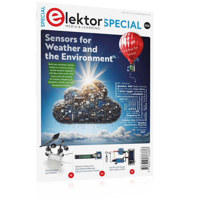
Elektor Special: Sensors for Weather and the Environment
Build your textbook weather station or conduct environmental research together with the whole world. With many practical projects for Arduino, Raspberry Pi, NodeMCU, ESP32, and other development boards. Weather stations have enjoyed great popularity for decades. Every current and even every long discontinued electronics magazine has regularly featured articles on building your own weather station. Over the years, they have become increasingly sophisticated and can now be fully integrated into an automated home — although this often requires loyalty to an (expensive) brand manufacturer across all components. With your own weather and environmental data, you can keep up and measure things that no commercial station can. It’s also fun: expand your knowledge of electronics, current microcontroller development boards and programming languages in a fun and meaningful way. For less than 10 euros you can get started and record your first environmental data — with time and growing interest, you will continue to expand your system. In this Edition Which Microcontroller Fits My Project? The Right Development Environment Tracking Wind and Weather Weather Display with OpenWeatherMap and Vacuum Fluorescent Display Volatile Organic Compounds in the Air We Breathe Working with MQ Sensors: Measuring Carbon Monoxide — Odorless but Toxic CO2 Traffic Light with ThingSpeak IoT Connection An Automatic Plant Watering System Good Indoor Climate: Temperature and Humidity are Important criteria Classy Thermometer with Vintage Tube Technology Nostalgic Weather House for the Whole Family Measuring Air Pressure and Temperature Accurately Sunburn Warning Device DIY Sensor for Sunshine Duration Simple Smartphone Says: Fog or Clear View? Identifying Earthquakes Liquid Level Measurement for Vessels and Reservoirs Water pH Value Measurement Detecting Radioactive Radiation GPS: Sensor Location Service Across the Globe Saving and Timestamping Log Files on SD Cards LoRaWAN, The Things Network, and ThingSpeak Operating a LoRaWAN Gateway for TTN Defying "Wind and Weather" Mega Display with Weather Forecasz
€ 19,95
Leden: € 17,96
-
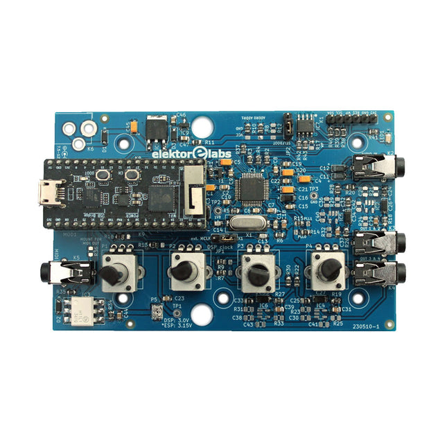
Elektor Labs Elektor Audio DSP FX Processor (Nieuwe Revisie)
De Elektor Audio DSP FX Processor combineert een ESP32-microcontroller en een ADAU1701 Audio DSP van Analog Devices. Naast een door de gebruiker programmeerbare DSP-kern heeft de ADAU1701 hoogwaardige analoog-naar-digitaal en digitaal-naar-analoog converters ingebouwd en is hij voorzien van een I²S-poort. Dit maakt hem geschikt als hoogwaardige audio-interface voor de ESP32. Programma's voor de ESP32 kunnen worden gemaakt met Arduino, Platform IO, CMake of door de Espressif IDF op een andere manier te gebruiken. Programma's voor de ADAU7101 audio DSP's worden gemaakt met de gratis visuele programmeertool SigmaStudio door voorgedefinieerde algoritmablokken op een canvas te slepen. Toepassingen Bluetooth/Wi-Fi audio sink (bijv. luidspreker) & bron Gitaareffectpedaal (stompbox) Muzieksynthesizer Geluids-/functiegenerator Programmeerbaar cross-overfilter voor luidsprekers Geavanceerde audio-effectprocessor (reverb, chorus, pitch shifting, enz.) Audioapparaat met internetverbinding DSP-experimentplatform Draadloze MIDI MIDI naar CV-converter en nog veel meer... Specificaties ADAU1701 28-/56-bit, 50-MIPS digitale audioprocessor die bemonsteringsfrequenties tot 192 kHz ondersteunt ESP32 32-bit dual-core microcontroller met Wi-Fi 802.11b/g/n en Bluetooth 4.2 BR/EDR en BLE 2x 24-bit audio-ingangen (2 V RMS, 20 kΩ) 4x 24-bit audio-uitgangen (0,9 V RMS, 600 Ω) 4x Regelpotentiometer MIDI in- en uitgang I²C-uitbreidingspoort Multi-mode werking Voeding: 5 V DC USB of 7,5-12 V DC (cilinderaansluiting, middelste pin is GND) Stroomverbruik (gemiddeld): 200 mA Inbegrepen 1x ESP32 Audio DSP FX Processor board (gemonteerd) 1x ESP32-PICO-KIT 2x Truien 2x 18-pins headers (female) 4x 10 KB potentiometers Downloads Documentation GitHub
€ 99,95€ 84,95Beste prijs
-
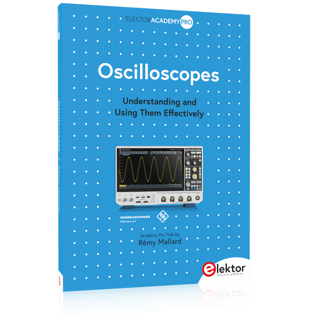
Elektor Publishing Oscilloscopes (Book)
Understanding and Using Them Effectively What happens in electronics is invisible to the naked eye. The instrument that allows to accurately visualize electrical signals, the one through which the effects of electronics become apparent to us, is the oscilloscope. Alas, when one first ventures into electronics, it is often without an oscilloscope. And one is left fumbling, both physically and mentally. Observing an electrical signal on a screen for the first time is a revelation. Nobody wishes to forgo that marvel again. There is no turning back. In electronics, if one wishes to progress with both enjoyment and understanding, an oscilloscope is essential. This marks the beginning of a period of questioning: how to choose one? And no sooner is that question answered than a whole string of others arises, which can be summed up in just one: how does one use the oscilloscope in such a way that what it displays truly reflects the reality of the signals? Rémy Mallard is a passionate communicator with a gift for making complex technical subjects understandable and engaging. In this book, he provides clear answers to essential questions about using an oscilloscope and offers a wealth of guidance to help readers explore and understand the electrical signals behind electronic systems. With his accessible style and practical insights, this book is a valuable tool for anyone eager to deepen their understanding of electronics.
€ 44,95
Leden: € 40,46
-

Édition spéciale : Les capteurs météorologiques et environnementaux
Construisez votre station météo idéale ou explorez les données environnementales avec le monde entier. Avec de nombreux projets pratiques pour Arduino, Raspberry Pi, NodeMCU, ESP32 et autres cartes de développement. Les stations météo jouissent d’une grande popularité depuis des décennies. Tous les magazines d’électronique, qu’ils soient récents ou non, ont publié et publient régulièrement des articles sur la construction d’une station météo. Au fil des années, elles sont devenues de plus en plus sophistiquées et peuvent aujourd’hui être entièrement intégrées dans la maison intelligente. Ceci implique toutefois souvent une fidélité à un fabricant de produits de marque (coûteux) pour tous les composants. Cependant, avec votre propre station météo, vous pouvez facilement suivre le rythme et même capturer des relevés que les appareils commerciaux ne peuvent pas réaliser. Le plaisir ne manque pas : vous développerez de manière ludique vos connaissances en électronique, en cartes de développement de microcontrôleurs modernes et en langages de programmation. Pour moins de dix euros, vous pouvez collecter des données environnementales initiales et étendre votre système au fur et à mesure que votre intérêt grandit. Dans ce numéro Sur la route du vent et de la météo Écran météo OpenWeatherMap à affichage fluorescent Les composés organiques volatils dans l‘air que nous respirons Travailler avec les capteurs MQ : mesurer le monoxyde de carbone Détecteur de CO2 avec connexion IdO vers ThingSpeak Un arrosage automatique pour vos plantes Un climat intérieur sain : la température et l‘humidité de l‘air sont importants Thermomètre avec tubes Nixie Une maison météo rétro pour toute la famille Mesurez la pression atmosphérique et la température avec précision Un détecteur de coups de soleil Capteur maison pour la durée d‘ensoleillement Le smartphone l‘indique : brouillard ou bonne visibilité ? Détecter les tremblements de terre Les niveaux des cours d‘eau et des réservoirs Évaluer la valeur du pH de l’eau Détecter les rayonnements radioactifs Avec le GPS, vous savez où se trouve votre capteur Enregistrer les fichiers journaux avec horodatage sur des cartes SD LoRaWAN, The Things Network et ThingSpeak Exploiter la passerelle LoRaWAN pour le TTN Affichage géant à led avec prévisions météo
€ 15,50
Leden: € 13,95
-
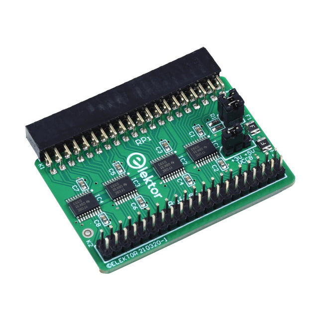
Elektor Labs Elektor Raspberry Pi Buffer Board
Wanneer u regelmatig experimenteert met de Raspberry Pi en verschillende externe hardware aansluit op de GPIO-poort via de header, heeft u mogelijk in het verleden schade veroorzaakt. Het Elektor Raspberry Pi Buffer Board is er om dit te voorkomen! Het board is compatibel met de Raspberry Pi Zero, Zero 2 (W), 3, 4, 5, 400 en 500. Alle 26 GPIO's zijn gebufferd met bidirectionele spanningsomzetters om de Raspberry Pi te beschermen tijdens het experimenteren met nieuwe circuits. De printplaat is bedoeld om aan de achterkant van de Raspberry Pi 400/500 te worden geplaatst. De connector voor aansluiting op de Raspberry Pi is een haakse 40-polige connector (2x20). De printplaat is slechts iets breder. Een 40-polige flatcable met bijpassende 2x20 headers kan worden aangesloten op de buffer-uitgangsheader om bijvoorbeeld te experimenteren met een circuit op een breadboard of een printplaat. Het circuit maakt gebruik van 4x TXS0108E IC's van Texas Instruments. De printplaat kan ook rechtop op een Raspberry Pi worden geplaatst. Downloads Schematics Layout
€ 34,95
Leden: € 31,46
-

Elektor Publishing Introduction to Electronic Filters
Learn RC and RL Filters with Hands-On Circuits and Simulation Introduction to Electronic Filters is your comprehensive guide to understanding, designing, and applying first-order electronic filters using resistors, capacitors, and inductors. Whether you are a student, maker, or educator, this book demystifies the theory behind RC and RL filters and bridges the gap between concepts and real-world applications through simulation and experimentation. From the basics of frequency response and phase shift to hands-on breadboard builds and Python-based simulations, this book offers a deeply practical learning experience. You will learn to analyse filters using Bode plots and phasors, and explore applications in audio tone shaping, sensor signal conditioning, noise reduction, and power supply filtering. As you progress, you’ll build, measure, simulate, and tune filters using modern tools like CircuitLab, Python, and the Analog Discovery 3. Each chapter includes thoughtfully crafted activities that reinforce learning by doing – designing filters for specific tasks, simulating dynamic behaviour, and observing how theory translates into performance. Inside you’ll find: A clear introduction to the fundamentals of electronic filters Detailed explanations of RC and RL filters, cutoff frequency, and phase Guided activities using both simulation and hardware tools Real-life applications in audio, sensors, power supplies, and more A beginner-friendly primer on Python and algebra for electronics Whether you’re working through simulations or experimenting with real components on your workbench, this book will help you develop a solid understanding of electronic filters and their role in practical circuits.
€ 39,95
Leden: € 35,96


