De OWON SDS1102 is een betaalbare benchtop digitale oscilloscoop die solide prestaties combineert met essentiële meetfuncties. Deze 2-kanaals oscilloscoop biedt een bandbreedte van 100 MHz, een sample rate van 1 GS/s, een 7-inch LCD-display en een geheugendiepte van 10 kpts. Daarmee is het een praktische keuze voor dagelijkse elektronicatests, foutopsporing en onderwijs.
De SDS1102 beschikt over een vereenvoudigd triggersysteem met niveau- en flanktriggering, waardoor gangbare signalen eenvoudig kunnen worden vastgelegd en geanalyseerd. Het apparaat is ontworpen voor toepassingen waarvoor geen grote geheugendiepte of geavanceerde triggerfuncties nodig zijn, en biedt een eenvoudige en kostenefficiënte oplossing voor basis-signaalanalyse.
Kenmerken
Bandbreedte: 100 MHz
2 kanalen
Bemonsteringssnelheid: 1 GS/s
Ultradunne behuizing
7-inch lcd met hoge resolutie
Ondersteuning voor SCPI en LabVIEW
Specificaties
Bandbreedte
100 MHz
Horizontale schaal (s/div)
5 ns/div - 1000 s/div
Kanalen
2
Verticale gevoeligheid
5 mV/div - 5 V/div (bij ingang)
DC Gain nauwkeurigheid
3%
Verticale resolutie (A/D)
8 bits (2 kanalen tegelijk)
Ingang
Ingangsimpedantie
1 MΩ, 10 pF
Ingangskoppeling
AC, DC, GND
Max ingangsspanning
± 400 V, CATI, CATII
Passieve probes
x1; 10
Probe verzwakkingsfactor
x1; x10; x100; x1000
Triggersysteem
Trigger mode
Auto, Normal, Single
Trigger type
Flank, Video
Flank triggerbron
CH1, CH2
Video trigger
Sampletype
Real-time
Samplefrequentie
1 GS/s
Equivalente samplesnelheid
No
Golflengte
10K pts
Interpolatie
sin(x)/x
Meet- en rekenkundig bewerkingssysteem
Automatische meting
Vpp, Vavg, RMS, Frequency, Period, Vmax, Vmin, Vtop, Vbase, Width, Overshoot, Pre-shoot Rise time, Fall time, +Width, -Width, +Duty, -Duty, Delay A->B, Delay A->B, area, cycle area
Rekenkundige functies
Addition, Subtraction, Multiplication, Division, FFT
Algemene kenmerken
Display maat
7" color LCD
Display resolutie
800 x 480
Voeding
100-240 V, 45-440 Hz, <15 W
Afmetingen
301 x 70 x 152 mm
Gewicht
1,1 kg
Inbegrepen
1x OWON SDS1102 Oscilloscoop
2x Oscilloscoopsonde
1x Sonde aanpassen
1x Netsnoer
1x USB-kabel
1x CD-Rom
1x Snelstartgids
Downloads
Quick Guide
Manual
PC Software
SCPI Commands
Example projects with Node-RED, MQTT, WinCC SCADA, Blynk, and ThingSpeak
This comprehensive guide unlocks the power of Modbus TCP/IP communication with Arduino. From the basics of the Modbus protocol right up to full implementation in Arduino projects, the book walks you through the complete process with lucid explanations and practical examples.
Learn how to set up Modbus TCP/IP communication with Arduino for seamless data exchange between devices over a network. Explore different Modbus functions and master reading and writing registers to control your devices remotely. Create Modbus client and server applications to integrate into your Arduino projects, boosting their connectivity and automation level.
With detailed code snippets and illustrations, this guide is perfect for beginners and experienced Arduino enthusiasts alike. Whether you‘re a hobbyist looking to expand your skills or a professional seeking to implement Modbus TCP/IP communication in your projects, this book provides all the knowledge you need to harness the full potential of Modbus with Arduino.
Projects covered in the book:
TCP/IP communication between two Arduino Uno boards
Modbus TCP/IP communication within the Node-RED environment
Combining Arduino, Node-RED, and Blynk IoT cloud
Interfacing Modbus TCP/IP with WinCC SCADA to control sensors
Using MQTT protocol with Ethernet/ESP8266
Connecting to ThingSpeak IoT cloud using Ethernet/ESP8266
LoRaWAN, Sigfox, NB-IoT & LTE-M Compared
The Internet of Things depends on a critical question. How do you connect devices that must operate for years on tiny batteries, often miles from the nearest power outlet? This Elektor Technical Brief provides a practical guide to the technologies that have become the backbone of long-range, low-power IoT connectivity. Compiled by the Elektor Content Team, this concise technical brief examines the real engineering tradeoffs behind today’s leading Low-Power Wide-Area Network (LPWAN) technologies: LoRaWAN, Sigfox, NB-IoT, and LTE-M.
By referencing a wide range of Elektor articles and other online content, this document explains why link budget, noise, bandwidth, and power consumption ultimately determine system performance. From there, it explores the architectures, strengths, limitations, and deployment realities of each major LPWAN technology, helping you understand not just how they work, but when and why to use them.
Whether you’re designing smart meters, industrial sensors, agricultural monitoring systems, asset trackers, or connected infrastructure, this guide provides the insights needed to make informed connectivity decisions. Along the way, you’ll discover:
Why LPWAN technologies emerged and where they fit in the IoT landscape
The RF fundamentals that drive range, reliability, and battery life
Details about LoRaWAN, Sigfox, NB-IoT, and LTE-M
Practical comparisons of power, coverage, latency, cost, and deployment models
Guidance for selecting the right LPWAN technology for your application
Emerging trends shaping the future of long-range IoT connectivity
Clear, accessible, and grounded in real engineering practice, this Technical Brief helps you move beyond specifications and marketing claims to understand what matters most. If you’re building connected products that need to survive in the field — not just in the lab — this is the LPWAN guide you’ll want at your side.
Elektor helped launch the first wave of electronics makers in 1961. Since then, our global community has grown by hundreds of thousands of active members (comprising professional engineers, makers, and students) and more than 500 contributing experts. Every day, we inspire members to design and earn money with electronics.
Una ricca selezione di articoli dal Mondo Elektor!
Gli articoli di questo libro sono una selezione accurata, il "meglio del meglio" di circuiti e progetti recenti, realizzati da tecnici di grande talento provenienti da tutto il mondo.
Nel tipico stile di Elektor, questa raccolta offre qualcosa di interessante per tutti, dai progettisti esperti a coloro che praticano l'elettronica nel tempo libero.
Sommario
Super Servo TesterProva Fino a Quattro Servocomandi, Stand-Alone o in Sistema
The TubeUn Insolito Amplificatore a Valvole
Cloc 2.0La Sveglia che Avete Sempre Desiderato
Stazione Meteo LoRa Low-PowerCostruitevi una Stazione Meteorologica “Long Range”
Uscita Video con Microcontrollori (Parte 1)Video Composito
Uscita Video con Microcontrollori (Parte 2)Uscita VGA e DVI
Un Raspberry Pi Pico come Analizzatore di SpettroFFT su Base Hardware a Basso Costo
PIC O’Clock – In Contatto col TempoProgettare un Ricevitore di Segnali Orari SDR
Frequenzimetro di Rete ACMisura Frequenza e Tensione della Rete Elettrica
Generatore di Funzioni con Arduino NanoNano + Codice = Generatore di Funzioni
Monitor CO2Un Approccio Fai-Da-Te per Il Controllo della Qualità dell‘Aria
ChatMagLevLa Levitazione Magnetica con AI
Alimentatore Lineare Variabile Combinato0…50 V / 0…2 A con Struttura Simmetrica Duale
Ricevitore Digitale FM con Arduino e TEA5767Restate in Ascolto con un Arduino Nano
Protezione Antigelo per Piante da FruttoCon Registrazione della Temperatura
Carico Elettronico con Generatore di clock IntegratoPer Collaudare Alimentatori, Convertitori di Tensione e Batterie
128 Termostato Web con ESP32Mantieni il Vino alla Giusta Temperatura
Iniezione di Segnali e di Potenza......per Rilevare le Interruzioni nei Cavi
DIY LiPo Supercharger KitDal Prototipo al Mercato di Massa
Livella Digitale con Stroboscopio AttivoCalibra il Tuo giradischi con Questo Strumento "Tutto-in-Uno"
The Game of Life – 262.144 Modi di GiocareDal Progetto di un Lettore
Rilevatore di PerditeCollegato ad Arduino Cloud
Orologio di LissajousL’Incedere del Tempo con le Figure di Lissajous
Mastermind – Controllato da ArduinoUna Versione Moderna del Classico Gioco di Decifrazione
Generatore Audio Analogico 1 kHzOnda Sinusoidale a Bassa Distorsione
Aggiorna il tuo Caricabatteria (Parte 1)Non Buttarlo, Modificalo!
Aggiorna il tuo Caricabatteria (Parte 2)Non Buttarlo, Modificalo!
Sistemi GNSS RTK a Basso CostoCon Accuratezza a Livello Centimetrico
Esperimenti a 10 GHz con LNB Satellitari ModificatiSbloccare la Banda X a Basso Costo
Telecamera per FerromodellismoInstalla un Modulo ESP32 CAM a Bordo!
Monitor di Tensione con MicrocontrolloreProtezione dalla Scarica Profonda per Batterie e Altro
Nodo Sensore AutonomoTrasmissione Dati LoRa con Alimentazione a Batterie Solari
Layout e Sicurezza sul PCBConsigli per un Progetto Sicuro e Durevole
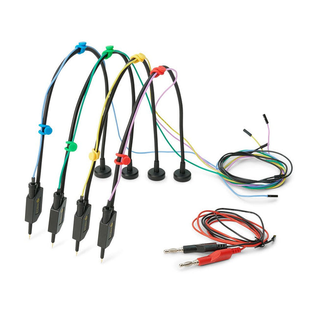
The SQ series of handsfree PCBite probes from Sensepeek are insulated, come with included color-coded cable holders and have a lower point of gravity making them even more stable compared with the original SP series of probes. All the loved features of handsfree measurement, exchangeable fine pitch spring tipped test needle and the minimalistic design is maintained to make traditional sized and handheld probes obsolete. Features All handsfree probes from Sensepeek makes instant measurements or long triggering sessions a breeze. No more soldering wires to connect your probe or complicated tools to setup, just positioning the probe needle on any test point or component in the signal path and release. Saves time and frustration during development, verification and repairs. The minimalist design and the spring-loaded test needle makes it possible to simultaneously measure on fine pitch components and nearby signals. Both length and weight of the SQ probes are perfectly balanced to be used with PCBite PCB holders and base plate which is a must for handsfree function. The probe holder comes with a powerful magnet in the base, as for all PCBite probes and holders which makes the probe easy to place and reposition. The SQ series of probes can be used handheld without the probe holder as they have an insulated grip but their full potential is used when measuring handsfree. Included 4x SQ10 probes and pin tipped test needles (black) 2x Banana to dupont test wires (red/black) 5x Dupont to dupont test wires 1x Set of cable holders (4 colors) 4x Extra test needles Downloads User guide
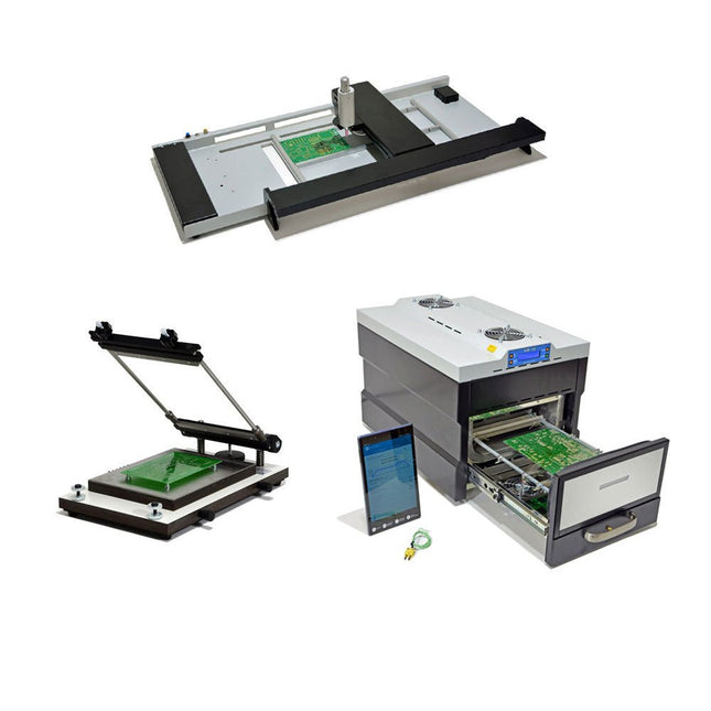
De SMD Starter I prototype-productielijn bestaat uit de TSD240 stencilprinter, de PlaceMAN SMD-plaatsingsmachine en de 3LHR10 reflow-oven. Stencilprinter SD240 (+ metalen rakel 155 mm) Stencilformaat: max. 175 x 255 mm Boardformaat: max. 180 x 240 mm Afmetingen basiseenheid: 410 x 270 x 110 mm Gewicht: 6,7 kg incl. metalen rakel 155 mm incl. 8 magneten om de printplaat vast te houden, waarvan 6 met M3-instelschroef incl. transparante plaatsingshulp en viltstift Handmatige SMD-plaatsingsmachine PlaceMAN voor standaardcomponenten incl. vacuümpomp (zonder feeders, camera, monitor en dispenser) Uitgerust met soepel lopende plaatsingsarm, plaatsingskop met eenhandsbediening, rotatie van de Z-as en automatische vacuümafsluiting, incl. printplaathouder, vacuümunit en 2 plaatsingsmondstukken met rubberen zuignappen. Capaciteit feeders (niet inbegrepen) 2x invoercassette voor 10 x 8 mm rollen links 4x invoercassette voor toevoereenheden van elk 5 magazijnen Verdere toevoersystemen zijn mogelijk binnen het plaatsingsgebied, bijvoorbeeld een insteeksysteem voor strooktoevoer. Afmetingen Basiseenheid (LxBxH): 765 x 390 x 210 mm Met invoercassette voor 10 x 8 mm rollen (LxBxH): 765 x 390 x 210 mm Met voedingscassette voor 10 x 8 mm rollen en voedingscassette voor magazijninvoer (LxBxH): 765 x 430 x 210 mm (hoogte kan variëren afhankelijk van de lengte van het magazijn) Met voedingscassette voor 10 x 8 mm rollen incl. houder voor 10 rollen en voedingscassette voor magazijninvoer (LxBxH): 765 x 430 x 210 mm (hoogte kan variëren afhankelijk van de lengte van het magazijn) Specificaties Gewicht basiseenheid: ca. 6 kg As verplaatsing (x,y,z): 470 x 230 x 15 mm Max. Werkgebied: 380 x 240 mm Max. PCB-formaat: 230 x 360 mm Voeding Netadapter: 230/12 V, 800 mA Voeding vacuümpomp: 230 V, 6 W 3LHR10 Reflow Oven (programmeerbaar voor loodvrij solderen met handmatige lade en met tabletbediening) Reflow-oven met IR- en convectieverwarming. Geforceerde hete lucht convectie zorgt voor een gelijkmatig temperatuurprofiel in de hele oven. Na het handmatige openen van de afsluiting worden de ventilatoren ingeschakeld en wordt de gesoldeerde printplaat snel afgekoeld. Kleine reflow-oven met handmatige opening Klaar voor Industrie 4.0, Bluetooth-communicatie + tablet IR + convectieverwarming. Android-app voor verbinding met tablet of smartphone 100 verschillende gebruikersprogramma's Leveringsomvang: 3LHR10, tablet met app, beschermhoes voor tablet, 4 printplaathouders, extern thermokoppel, handleiding in tablet Toepassing Sluit de oven aan op het elektriciteitsnet en sluit de optioneel verkrijgbare afzuigunit (3LFE10S) aan op de luchtafvoeraansluiting. Na de eerste keer inschakelen zoekt de oven naar een tablet of smartphone. Wanneer beide verbonden zijn in de Android-app, selecteer je de programmering van de oven. Hier kunnen de temperatuur en voorverwarmingstijd worden ingesteld, evenals andere dingen. Registreer je met de tablet om de software in zijn geheel te kunnen gebruiken. Als de oven al geprogrammeerd is, kan de gebruiker het proces bedienen met de knoppen en het display aan de voorkant. Er klinkt een toon wanneer het reflow proces is voltooid. Er wordt ook een signaal weergegeven op de tablet/smartphone. De lade moet nu handmatig worden geopend. De Android-app geeft de processtatus, tijd en temperatuur of andere informatie weer. Specificaties Netaansluiting: 230 V, 50 Hz Maximaal vermogen: 3100 W Temperaturen: 50-260°C Afmetingen: 510 x 370 x 340 mm Maximaal gewicht: 16 kg Afmetingen rooster: 350 x 220 mm Maximale afmetingen van de printplaat: 300 x 200 mm Maximale componenthoogte op de PCB: 50 mm boven, 30 mm onder Leveringsomvang Stencilprinter TSD240 SMD-plaatsingsmachine PlaceMAN Reflow-oven 3LHR10
Erste Schritte ins IoT - mit dem ESP32-C3WLAN-Taster und -Relais
IoT-Cloud à la ArduinoErster Kontakt mit der Arduino-Cloud
Arduino-Shield für zwei Geiger-Müller-ZählrohreEin hochempfindlicher, sehr stromsparender Strahlungsmesser
CO2-WächterEin DIY-Ansatz zur Überwachung der Luftqualität
MonkMakes: Luftqualitäts-Messgerätekit für den Raspberry PiMisst Temperatur und CO2e
Aller Anfang ...muss nicht schwer sein: Willkommen bei der Diode!
Beherrschen Sie die Fachsprache?Fünf praktische Tipps für Ingenieure
Tipps & Tricks beim BauteiltestRecycling ohne teures Messequipment
Stromsparende MaulwurfscheucheEin ATtiny13 ersetzt einen 555er
Lichtschalter DeLuxEine Lösung für hochpräzises lichtgesteuertes Schalten
Herausforderungen bei der Markteinführung von IoT-LösungenSorgen um Sicherheit, Skalierbarkeit und Wettbewerb
Infografik 5-6/2022
Lieber doch verkabeltTipps zur Entwicklung einer 1-Gbit/s-Schnittstelle im Industrieumfeld
Objekterkennung in Echtzeit für MCUs mit Edge Impulse FOMO
WanderfeldröhrenBemerkenswerte Bauteile
NB-IoT - ein ÜberblickStandards, Abdeckung, Verträge und Module
Dragino LPS8 Indoor GatewaySchnell zum eigenen LoRaWAN-Gateway
ATtiny-Mikrocontroller mit C und Assembler erforschenBeispiel-Kapitel: I/O-Ports des ATtiny
Projekt 2.0Korrekturen, Updates und Leserbriefe
LoRa-GPS-Tracker - ein UpdateDaten abholen und visualisieren mit dem Raspberry Pi
Schaltungssimulation mit TINA Design Suite und TINACloudBeispiel-Kapitel: Sinusförmige Oszillatoren
WinUI 3: Neues Grafik-Framework für Windows-AppsEine erste App für Elektroniker
GUIs mit Python:Die schlechteste GUI der Welt
Insel-SolaranlagenElektrische Energie unabhängig vom Netz
Das 10-Jahres-HandyErneuern Sie Ihre Erwartungen!
Hexadoku
The 2-channel OWON XDG2035 is a function/waveform generator that can generate signals with a maximum frequency of 35 Hz. The generator has a resolution of 1 µHz and a sample rate of 500 MSa/s.The OWON XDG2035 is capable of generating 6 standard waveforms and 150 arbitrary waveforms. With the included software you can write advanced functions up to 10 million points. Waveforms can be saved to the function generator's internal memory using a PC via USB or LAN.The OWON XDG2035 also supports SCPI commands and LabView. The function generator has an integrated high-quality frequency counter, which can operate from 100 to 200 MHz.Features
Max. 35 MHz frequency output
500 MSa/s Sample rate, Vertical resolution 1μHz
14 bits Vertical Resolution, 10 Marb waveform length
Comprehensive waveform output: 6 basic waveforms,and 150 built-in arbitrary waveforms
Comprehensive modulation functions: AM, FM, PM, FSK, 3FSK, 4FSK, PSK, OSK, ASK, BPSK, PWM, Sweep, and Burst
High-accuracy frequency counter integrated, supported range 100-200 MHz
SCPI and LabVIEW supported
7 inch multi-touch screen (800 x 480 pixels)
Specifications
Channel
2
Frequency Output
35 MHz
Sample Rate
500 MSa/s
Vertical Resolution
14 bits
Waveform
Standard Waveform
sine, square, pulse, ramp, noise, and harmonic
Arbitrary Waveform
exponential rise, exponential fall, sin(x)/x, step wave, and others, total 150 built-in waveforms, and user-defined arbitrary waveform
Frequency (resolution 1 μHz)
Sine
1 μHz-100 MHz
Square
1 μHz ~ 30 MHz
Pulse
1 μHz ~ 25 MHz
Ramp
1 μHz ~ 3 MHz
Noise (-3 dB, typical)
100 MHz
Arbitrary Waveform
1 μHz ~ 15 MHz
Harmonic
1 μHz ~ 50 MHz
Accuracy
±2ppm, 25°C ±5°C
Waveform Length
2 points - 10M points
Amplitude
Into 50Ω load
1mVpp ~ 10Vpp (≤25 MHz); 1mVpp ~ 5Vpp (≤60 MHz); 1mVpp ~ 2.5Vpp (≤100 MHz)
Modulation
Type
AM, DSB-AM, FM, PM, ASK, FSK, PSK, BPSK, QPSK, 3FSK, 4FSK, OSK, PWM, SUM
Frequency Counter
Function
Frequency, period, +width, -width, +duty, and -duty
Frequency Range
100 ~ 200 MHz
Frequency Resolution
7 digits
Input/Output
Input mode
frequency counter, external modulation input, external trigger input, internal clock output, external reference clock input/output
Communication Interface
USB Host, USB Device, LAN, RS232 (optional)
Mechanical specifications
Dimensions
340 x 177 x 90 mm
Weight
2.3 kg
Included
1x OWON XDG2035
1x Power Cord
1x CD-ROM
1x Quick start guide
1x USB Cable
1x BNC-BNC Cable
DownloadsQuick Guide
310 Circuits – is the 11th volume in Elektor’s renowned ‘Three Hundred’ series. 310 circuits, tips and design ideas in one book form a treasure trove for every area of electronics: audio and video, hobby and modelling, RF techniques, home and garden, test and measurement, microcontrollers, computer hardware and software, power supplies and chargers – plus of course everything else that does not seem to belong in any of these categories.
310 Circuits – contains many complete solutions as well as useful starting points for your own projects. Both categories and anything in between represent a veritable fountain of inspiration for cultivating your own ideas and learning about electronics.
310 Circuits – is a compilation of articles from ‘Summer Circuits’ editions for the years 2006, 2007 and 2008. ‘Summer Circuits’ covers the publication months July and August of Elektor magazine.
310 Circuits – is a must-have book for every creative electronics enthusiast, be it professional, enthusiast or student.
310 Circuits – for the first time has a section exclusively on robots and robotics.
The Siglent SDS1204X-E is a powerful 200 MHz four-channel oscilloscope that is built on the same platform as the very popular SDS1202X-E but with several significant improvements, including two 1 GSa/s ADCs and two 14 Mpt memory modules. Waveform capture rates are up to 100,000 wfms/s in normal mode and 400,000 wfms/s in sequence mode. The SDS1000X-E scopes feature a large 7” 256-level color display with intensity grading and color temperature features.
Specificaties
Bandwidth
200 MHz
Sampling Rate (Max.)
1 GSa/s
Channels
2CH+EXT4CH
Memory Depth (Max.)
7 Mpts/CH (not interleave mode); 14 Mpts/CH (interleave mode)
Waveform Capture Rate (Max.)
100,000 wfms/s (normal mode), 400,000 wfms/s (sequence mode)
Trigger Types
Edge, Slope, Pulse width, Window, Runt, Interval, Dropout, Pattern, Video
Serial Trigger (Standard)
I2C, SPI, UART/RS232, CAN, LIN
Decode Type (Standard)
I2C, SPI, UART/RS232, CAN, LIN
16 Digital Channels (four channel series only, option)
Maximum waveform capture rate up to 1 GSa/s, Record length up to 14 Mpts/CH
USB AWG module (four channel series only, option)
One channel, 25 MHz, sample rate of 125 MHz, wave length of 16 kpts
Bode plot ( four channel series only)
Minimum start frequency of 10 Hz, minimum scan bandwith of 500 Hz, maximum scan bandwidth of 120 MHz (dependent on Oscilloscope and AWG bandwidth), 500 maximum scan frequency points
USB WIFI adapter (four channel series only, option)
802.11b/g/b, WPA-PSK, the adapter must be supplied by Siglent to ensure proper functioning
Downloads
Datasheet
Manual
Programming Guide
De SQ-serie handsfree PCBite-sondes van Sensepeek zijn geïsoleerd, worden geleverd met meegeleverde kleurgecodeerde kabelhouders en hebben een lager zwaartepunt waardoor ze nog stabieler zijn vergeleken met de originele SP-serie sondes. Alle geliefde kenmerken van handsfree meten, een verwisselbare testnaald met veertip en het minimalistische ontwerp zijn behouden gebleven, waardoor traditionele en draagbare sondes overbodig zijn geworden.
Kenmerken
Alle handsfree sondes van Sensepeek maken directe metingen of lange triggersessies een fluitje van een cent.
Geen soldeerdraden meer om uw sonde aan te sluiten of ingewikkelde gereedschappen om in te stellen, u hoeft alleen maar de sondenaald op een willekeurig testpunt of onderdeel in het signaalpad te plaatsen en los te laten.
Bespaart tijd en frustratie tijdens ontwikkeling, verificatie en reparaties.
Het minimalistische ontwerp en de veerbelaste testnaald maken het mogelijk om tegelijkertijd te meten op fijne toonhoogtecomponenten en signalen in de buurt.
Zowel de lengte als het gewicht van de SQ-sondes zijn perfect uitgebalanceerd voor gebruik met PCBite PCB-houders en basisplaat, wat een must is voor handsfree functioneren.
De sondehouder wordt geleverd met een krachtige magneet in de basis, zoals bij alle PCBite-sondes en -houders, waardoor de sonde gemakkelijk te plaatsen en te verplaatsen is.
De sondes uit de SQ-serie kunnen zonder de sondehouder in de hand worden gebruikt, omdat ze een geïsoleerde handgreep hebben, maar hun volledige potentieel wordt benut bij handsfree meten.
Inbegrepen
4x PCBite PCB-houders
2x SQ10-sondes en testnaalden met pintip (rood/zwart)
2x Banaan naar dupont-testdraden (rood/zwart)
1x Grote bodemplaat (A4)
1x Isolatiehoes voor de bodemplaat (A4)
1x Set gele isolatieringen voor de PCB-houders
1x Set kabelhouders (rood/zwart)
2x Extra testnaalden
1x Microvezeldoek
Downloads
User Guide (PCBite Kit)
User Guide (SQ10)