
Zoekresultaten voor "official OR raspberry OR pi OR 7 OR inch OR touch OR display"
-

Elektor Digital Elektor Januari/Februari 2021 (PDF)
ZELFBOUW LIPO- SUPERCHARGER-BUNDELLiPo-lader, -booster en -beveiliging van GreatScott en Elektor MTHECAM – DE MINI-THERMOCAMERAeenvoudige warmtebeeldcamera voor het lokaliseren van hot- en coldspots REVIEW: WELLER-SOLDEERSTATION WE 1010 ELECTRONICA FAST FORWARD 2020 – DE WINNAARS I2S TESTSIGNAALGENERATOR MET AVR-MICROCONTROLLER32-bit 1-kHz digitale sinus, fs 192 kHz, niveau instelbaar van 0 tot –110 dB DOMOTICA MET DE RASPBERRY PIRPi luistert op 433,92 MHz SCHAKELINGEN ONLINE SIMULEREN UIT HET LEVEN GEGREPENde dunne grens tussen orde en chaos ALLE BEGIN......hoeft niet zo moeilijk te zijn OOST WEST LAB BESTeen blik in het allerheiligste, waar interessante projecten worden geboren VERBIND UW THERMOSTAAT MET ESPHOMEeen poging om domotica op de juiste manier te doen DEVELOPER’S ZONEtips & trucs, vakkunstigheden en andere nuttige informatie WIE HET KLEINE NIET EERTuit de ideeënbus van Elektor RASPBERRY PI FULL STACKRPi en RF24 als hart van een sensornetwerk MULTITASKING MET DE ESP32 (6)event groups MEERKANAALS POWER ANALYZERtot 3 kanalen, met grafisch en alfanumeriek display ANALOGE ELEKTRONICA ONTWERPENcase-study #2 – deel 3: passieve filters REVIEW: DRAADLOZE MEETMODULE JOY-IT VAX-1030 NIEUWE LCR-METER 50 HZ – 2 MHZ (DEEL 2)bediening, kalibratie en programmeren van de firmware ERROR ANALYSIStips en trucs: spanningsregelaars, PCB-ontwerp en meer HET OPEN HARDWARE OBSERVATORYcommunitygebaseerde beoordeling van open source-hardware JAVA OP DE RASPBERRY PIeen vraaggesprek met Frank Delporte DATA-ANALYSE EN KUNSTMATIGE INTELLIGENTIE IN PYTHONechte gegevens interpreteren met NumPy, pandas en scikit-learn INTERACTIEFcorrecties & updates || brieven van lezers ONZE COMMUNITY IN CIJFERS KENNISMAKING MET DE PARALLAX PROPELLER 2 (DEEL 1)inleiding HEXADOKU
€ 9,95
-

OWON OWON ADS914A 4-kanaals Oscilloscoop (125 MHz)
De OWON ADS900A-serie is een compacte 12-bits digitale oscilloscoop met een snelheid tot 2 GSa/s, een geheugen van 100 Mpts en een bandbreedte van 125/250 MHz. Met zijn 7-inch multi-touch display, FFT, protocoldecodering en geïntegreerde logic analyzer levert hij nauwkeurige signaalanalyse voor toepassingen in het laboratorium, de werkplaats en in het veld. Specificaties ADS914A ADS924A Bandwidth (-3 dB) 125 MHz 250 MHz Channels 4 Max. sample rate 2 GSa/s (single-channel) 1 GSa/s (dual-channel) 500 MSa/s (full-channel) DC Gain Accuracy 3% (≤1 mV) 2% (≥2 mV) Max memory depth 100M Vertical resolution 12 bits Relay time accuracy ±25 ppm (typical) Input Impedance 1 MΩ±2%, parallel with20 pF±5 pF Probe Attenuation Coefficient 1.00μX-1M.00X,step by 1-2-5, support custom Trigger type Edge, Video, Pulse, Slope, Runt, Windows, Timeout, Nth, Logic, RS232/UART, I²C, SPI CAN, LIN Bus decoding RS232/UART, I²C, SPI, CAN, LIN Auto measurement Period, Frequency, +Width, -Width, Rise Time, Fall Time, Scr Duty, +Duty,-Duty, Vavg, Vpp, VRMS, Overshoot, Vmax, Vmin, Vtop, CycRms, Vbase, Vamp, Preshoot, Std Dev, +Pulse Cnt, -Pulse Cnt, Rise Cnt, Fall Cnt, Area, Cyc Area, Delay(A↑-B↑), Delay(A↑-B↓), Delay(A↓-B↑), Delay(A↓-B↓), Phase(A↑-B↑) Phase(A↑-B↓), Phase(A↓-B↑), Phase(A↓-B↓), FRR(A↑-B↑), FRF(A↑-B↓) FFR(A↓-B↑), FFF(A↓-B↓), LRR(A↑-B↑), LRF(A↑-B↓), LFR(A↓-B↑), LFF(A↓-B↓) Waveform Math +, -, *, /, &&, ||, ^, !, Intg, Diff, Sqrt, Function operation (Lg / Ln / Exp / Abs / Sine / Cosine / Tan), FFT, FFT rms, User Defined, digital filter (low pass, high pass, band pass, band reject) Frequency counter 6-digit frequency counter Maximum frequency: maximum analog bandwidth of oscilloscope Voltmeter Support DC, AC+DCrms, ACrms, Resolution: 4 digits (ACV/DCV) Logical Analyzer Specifications Number of channels 16 input channels (D0-D15) (D0 to D7, D8 to D15) Max. input voltage ±40V peak CAT I, transient overvoltage 800Vpk Input Impedance 100kΩ, 8 pF Vertical resolution 1 bit Other Communication Interface HDMI, USB device, USB Host, Trig Out (P/F), LAN Display 7 inch (1024x600), capacitive multi-touch screen Power supply interface USB-C Dimensions 260 x 160 x 78 mm Weight 1.5 kg Inbegrepen 1x OWON ADS914A Oscilloscoop 1x Voedingsadapter 1x Netsnoer 1x USB-kabel 1x Probe 1x Quick Guide Downloads Manual Quick Guide PC Software
€ 579,59
-

Elektor Digital Elektor 01-02/2025 (PDF) DE
Diese Ausgabe steht allen GOLD- und GREEN-Mitgliedern auf der ElektorMagazine-Website zum Download bereit! Sie sind noch kein Mitglied? Hier klicken! DIY-SolarakkusÜber den Selbstbau von Energiespeichern für Solaranlagen Solarmodul-SimulatorFür Test und Optimierung von MPP-Trackern und Invertern Der STM32-Edge-KI-WettbewerbEntdecken Sie den neuen STM32N6 und nehmen Sie am Wettbewerb um 5.000 € teil! Erweiterung der BandlückeWarum gibt es so viel Interesse an SiC und GaN? Power-Bank für NotebooksVerlängern Sie das Leben Ihres alten Laptops! Medizinische RoboterÜberwindung technischer und regulatorischer Hürden Frostwächter für ObstpflanzenMit Temperatur-Datenlogger Das analoge DingDer Arduino des Analog-Computings? Sparsames NetzrelaisMit über 90% Leistungsreduzierung Verbesserung der DC-Last ET5410A+Keep cool and be quiet! electronica 2024 im Rückblick Elektromagnetische VerträglichkeitEMV kurz und bündig! Aller Anfang......muss nicht schwer sein: Aktive Filter Verlustleistung reduzieren mit AbleitkondensatorenEin cleverer Einsatz von kapazitiver Reaktanz Preiswerter 12-Bit-Digital-Analog-Wandler MCP4725Mit EEPROM-Feature für sicheres Einschaltverhalten Fnirsi LCR-ST1, die intelligente LCR-SMD-Pinzette Test- und Messlabor mit Raspberry PiDas Wichtigste zuerst: Der ADC Elektronischer LastwiderstandEin Projekt aus der Kiste 2025: Eine Odyssee in die KIEinige Projekte für das neue Jahr Projekt-Update: Modulares DC-Leistungsmessgerät AmpVolt v2.0100 Ampere und mehr! Projekt 2.0 Ethische Transparenz sichtbar gemachtErgebnisse der Umfrage 2024 von Ethics in Electronics Elektor Audio-DSP FX-Prozessor-BoardTeil 2: Anwendungen erstellen
€ 11,90
-

Elektor Digital Elektor July/August 2023 (PDF)
Elektor GREEN and GOLD members can download their digital edition here. Not a member yet? Click here. Rotary Dial Phone as Remote ControlTo Switch On the Lights, Dial 1; For the Coffee Maker, Dial 2 GPS-Based Speed MonitorNo More Speeding Tickets RGB Stroboscope with ArduinoA Colorful Adaptation of a Useful Instrument Wireless Emergency Push ButtonEnhanced Safety with LoRa Starting Out in ElectronicsFollow the Emitter Arbitrary, Independent Hysteresis Levels for Comparatorswith Simulations, Spreadsheets and Algebra ESP32-Based Impedance AnalyzerSimple, Low-Part-Count, and Inexpensive! HomeLab ToursEncouraging DIY The MCCAB Arduino Nano Training BoardAll-in-One Hardware for the “Microcontrollers Hands-On Course” From Life’s ExperienceModern Luddism Sensor 101: The DS18B20 Temperature SensorConnection to the 1-Wire Bus Is Matter the Thread to Save the Smart Home?New Standards to Simplify the Smart Home A Matter of CollaborationDeveloping with the Thing Plus Matter Board and Simplicity Studio Infographics: IoT and Sensors Matter, ExpressLink, Rainmaker — What Is This All About?Q&A with Amey Inamdar, Technical Marketing Director at Espressif Selecting Microcontroller Dev Kits for IoT and IIoT ApplicationsAn Introductory Guide Capacitors Do Not Always Behave Capacitively! An NTP Clock with CircuitPythonWhy Should You Use This Programming Language? Build a Cool IoT DisplayWith the Phambili Newt The HB100 Doppler Motion SensorTheory and Practice A Bare-Metal Programming Guide (Part 1)For STM32 and Other Controllers Siglent SDM3045X Multimeter Microprocessors for Embedded SystemsPeculiar Parts, the Series Microcontroller Documentation Explained (Part 3)Block Diagrams and More Low-Power LoRa Weather StationBuild a long-range weather station by yourself Transverter for the 70 cm Band Climate Calling EngineersMove Fast and Fix Things Hexadoku
€ 7,50
-

Great Scott Gadgets Acryl behuizing voor HackRF SDR
Deze doorzichtige acryl behuizing is de officiële behuizing voor het HackRF One/Pro board. Hij kan de standaard zwarte plastic behuizing van de HackRF One/Pro vervangen. Montage-instructies Gebruik een plectrum of spudger om de HackRF One/Pro printplaat uit de zwarte plastic behuizing te halen. Steek een lange schroef in elke hoek van het onderste acrylpaneel. Zet elke lange schroef vast met een kort afstandsstuk (5 mm) aan de tegenoverliggende kant van het paneel. Plaats de HackRF One/Pro printplaat (naar boven gericht) bovenop het onderpaneel en steek de uiteinden van de lange schroeven door de bevestigingsgaten in de hoeken van de print. Zet de printplaat vast met een lang afstandsstuk (6 mm) in elke hoek. Plaats het bovenste acrylpaneel op de printplaat en lijn de uitsparingen uit met de extension headers op de print. Zet elke hoek vast met een korte schroef. Opmerking: Niet te strak aandraaien! Na elke stap alleen met de hand aandraaien.
€ 19,95
Leden: € 17,96
-

Elektor Digital Elektor May/June 2022 (PDF)
Your First Steps with an ESP32-C3 and the IoTA Wi-Fi Button and Relay IoT Cloud a la Arduino Dual Geiger-Müller Tube Arduino ShieldA High Sensitivity, Very Low-Power Radiation Sensor CO2 GuardA DIY Approach to Monitoring Air Quality MonkMakes Air Quality Kit for Raspberry PiMeasures Temperature and eCO2 Starting Out in ElectronicsWelcome to the Diode Tips & Tricks for Testing ComponentsNo Expensive Equipment Required Reducing the Power Consumption of Your Mole RepellerAn ATtiny13 Replaces a 555 Light Switch DeLuxA Solution for High-Precision Light-Controlled Switching The Challenges in Bringing IoT Solutions to MarketWorries Around Security, Scalability, and Competition Infographics 5-6/2022 Preferably Wired After AllTips for Developing a 1 Gbit/s Interface in an Industrial Environment Bringing Real-Time Object Detection to MCUs with Edge Impulse FOMO Traveling-Wave TubesPeculiar Parts, the Series Narrowband Internet of ThingsStandards, Coverage, Agreements, and Modules Dragino LPS8 Indoor GatewaySpeedy LoRaWAN Gateway Setup Explore ATtiny Microcontrollers Using C and Assembly LanguageSample Chapter: ATtiny I/O Ports Err-lectronicsCorrections, Updates and Readers’ Letters LoRa GPS Tracker UpdateReceive and Show Location Using a Raspberry Pi Circuit Simulation with TINA Design Suite & TINACloudSample Chapter: Sinusoidal Oscillators From Life’s ExperienceAssembly Line Work The WinUI Graphics Framework for Windows AppsA Small Demo Application GUIs with PythonWorst GUI of the world Off-Grid Solar SystemsElectrical Energy Independent of the Mains Grid The 10-Year SmartphoneRenew Your Expectations HexadokuThe Original Elektorized Sudoku
€ 7,50
-

Elektor Digital Elektor January/February 2021 (PDF) EN
DIY LiPo Supercharger BundleGreatScott and Elektor's LiPo Charger, Booster, and Protector MTheCamA Simple Mini Thermal Camera Weller WE 1010Soldering Station electronica Fast Forward 2020 Winners I2S Test Signal Generator with AVR Microcontroller32-Bit 1-kHz Digital Sine, fs 192 kHz, Level Adjustable from 0 to -110 dB Control Your Home with Raspberry PiRPi snoops on 433.92 MHz Simulate Circuits Online From Life's ExperienceThe Fine Line Between Order and Chaos Starting Out in ElectronicsEasier Than imagined! Homebrew CPUsThe Discrete Microcontroller Connect Your Thermostat with ESPHomeAn Attempt at Doing Home Automation the Right Way Developer’s ZoneTips & Tricks, Best Practices and Other Useful Information Small Circuits RevivalFrom the Elektor suggestions box Raspberry Pi Full StackRPi and RF24 at the heart of a sensor network Practical ESP32 Multitasking (6)Event Groups Multi-Channel Power Analyzer: Up to 3 Channels, with Graphic and Alphanumeric Display Analogue Filter Design (Part 3)Passive Filters JOY-iT VAX-1030Wireless Measurement Module New LCR Meter 50 Hz - 2 MHz Part 2Operation, Calibration, and Firmware Programming Error AnalysisTips on Voltage Regular Circuits, PCB Design, and More The Open Hardware ObservatoryCommunity-Based Open Source Hardware Assessment Java on the Raspberry PiAn Interview with Frank Delporte Data Analysis and Artificial Intelligence in PythonInterpreting Real Data with NumPy, pandas and scikit-learn Project 2.0Corrections, Updates and Readers’ letters Getting to Know the Parallax Propeller 2 (Part 1)An Introduction Hexadoku
€ 7,50
-

OWON OWON SDS1104 4-kanaals Oscilloscoop (100 MHz)
De OWON SDS1104 oscilloscoop is een praktische keuze voor engineers, technici, studenten en hobbyisten die nauwkeurige signaalanalyse nodig hebben zonder de kosten van hoogwaardige meetinstrumenten. Met een bandbreedte van 100 MHz en een samplingrate van 1 GSa/s legt hij laag- tot middenfrequente signalen betrouwbaar vast, waardoor hij zeer geschikt is voor elektronicaontwikkeling, foutopsporing en educatief gebruik. Uitgerust met een 7-inch kleuren-TFT-display biedt de SDS1104 een duidelijke weergave van golfvormen, terwijl automatische meetfuncties en FFT-analyse gebruikers helpen om frequentie-, spannings- en timingparameters snel te beoordelen. Geavanceerde wiskundige bewerkingen, cursormetingen en meerdere triggermodi zorgen voor extra flexibiliteit, waardoor de oscilloscoop een veelzijdig hulpmiddel is voor uiteenlopende testsituaties. Specificaties Bandwidth 100 MHz Sample Rate 1 GS/s Horizontal Scale (s/div) 5ns/div - 1000s/div, step by 1 - 2 - 5 Channel 4 Display 7" color LCD, 800 x 480 pixels Input Coupling DC, AC and GND Vertical Resolution (A/D) Vertical Resolution (A/D) Vertical Sensitivity 5mV/div - 5V/div (at input) Trigger Type Edge, Video Trigger Mode Auto, Normal and Single Waveform Math +, -, x, ÷, invert, FFT Fuse 2A, T class, 250 V Dimension (W x H x D) 301 x 152 x 70 mm Weight 1.1 kg Inbegrepen 1x OWON SDS1104 Oscilloscope 1x Mains power cord 1x CD Rom 1x Quickstart Guide 1x USB Cable 4x Oscilloscope probe 1x Probe Adjust Downloads Datasheet Manual
€ 249,00
-
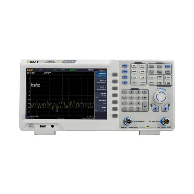
OWON OWON XSA815-TG Spectrum Analyzer (9 kHz – 1.5 GHz)
The OWON XSA815-TG 9 kHz-1.5 GHz is a cost effective spectrum analyzer with tracking generator included and a frequency resolutions of 1 Hz.Features Frequency Range from 9 kHz to 1.500009 GHz 9-inch display 9 kHz to 1 MHz -95 dBm Displayed Average Noise Level, 1 MHz to 500 MHz 140 dBm (Typical), <-130 dBm Phase Noise -10 kHz < -80 dBc/Hz 100 kHz < -100 dBc/Hz 1 MHz < -115 dBc/Hz Resolution Bandwidth (-3 dB): 1 Hz to 1 MHz, in 1-3-5-10 sequence Tracking Generator Kit: 100 kHz to 1.500009 GHz Specifications Frequency Range 9 kHz to 500.009 MHz Frequency Resolution 1 Hz Frequency Span 9 kHz to 1.500009 GHz Span Range 0 Hz, 100 Hz to max frequency of instrument Span Uncertainty ± span / (sweep points-1) SSB Phase Noise (20°C to 30°C, fc=1 GHz) Carrier Offset 10 kHz < -80 dBc/Hz | 100 kHz < -100 dBc/Hz | 1 MHz < -115 dBc/Hz Resolution Bandwidth (-3 dB) 1 Hz to 1 MHz, in 1-3-5-10 sequence RBW Accuracy < 5% typical Resolution Filter Shape Factor (60 dB: 3 dB) <5 typical Video Bandwidth (-3 dB) 10 Hz to 1 MHz, in 1-3-5-10 sequence Amplitude measurement range DANL to +10 dBm, 100 kHz to 10 MHz, Preamp Off DANL to +20 dBm, 10 MHz to 1.5 GHz, Preamp Off Reference Level -80 dBm to +30 dBm, 0.01dB by step Preamp 20 dB, nominal, 100 kHz to 1.5 GHz Input Attenuator 0 to 40 dB, 1 dB by step Display Average Noise Level Input attenuation = 0 dB, RBW = VBW = 100 Hz, sample detector, trace average ≥ 50, 20°C to 30°C, input impedance = 50 Ω) Preamp Off 9 kHz to 1 MHz -95 dBm (Typical), <-88 dBm Preamp Off 1 MHz to 500 MHz -140 dBm (Typical), <-130 dBm Preamp On 100 kHz to 1 MHz -135 dBm (Typical), <-128 dBm Preamp On 1 MHz to 500 MHz -160 dBm (Typical),<-150 dBm Tracking Generator (optional) Frequency Range 100 kHz to 1.500009 GHz Output power level range -40 dBm to 0 dBm Output level resolution 1 dB Output flatness Relative to 50 MHz | ±3 dB Tracking generator spurious Harmonic spurious -30 dBc (Tracking generator output power -10 dBm) Non-harmonic spurious -40 dBc (Tracking generator output power -10 dBm) Tracking generator to input terminal isolation -60 dB (Tracking generator output power 0 dBm) Tracking generator to input terminal isolation -60 dB (Tracking generator output power 0 dBm) Tracking generator to input terminal isolation -60 dB (Tracking generator output power 0 dBm) Dimensions 375 x 185 x 120 mm Weight 3.7 kg Included 1x XSA815-TG 1x 220 V AC power cord 1x USB Cable 1x Quickstart guide Downloads Quick Guide Specifications
€ 907,50
-
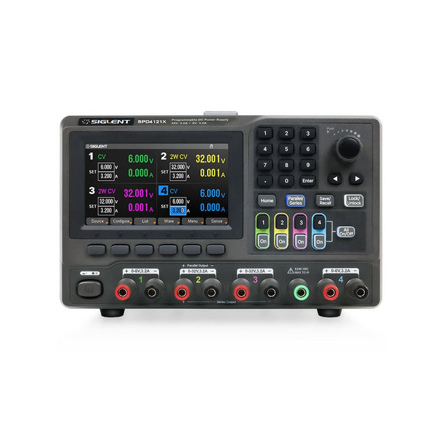
Siglent Siglent SPD4121X 4-kanaals Voeding (285 W)
The Siglent SPD4121X is a 4-channel DC Linear Programmable Power Supply equipped with a 4.3-inch TFT-LCD display, friendly human-machine interface, and excellent performance indicators. Real-time waveform display provides engineers with an informative user interface. SPD4121X offers a total output power of 285 W with a resolution of 1 mV/1 mA. The maximum voltage and current for each channel are as follows: CH1: 15 V/1.5 A CH2: 12 V/10 A CH3: 12 V/10 A CH4: 15 V/1.5 A Kenmerken Rated output power: 285 W Rated voltage: 32 V, 12 V, 30 V Up to four high-precision power supplies with independent controllable outputs, supporting CH2 and CH3 series and parallel connections Clear graphical interface with waveform and timer display modes 5-digit voltage and current display with minimum resolution of 1 mV, 1 mA Fast output response time: <50us The high current channel support remote voltage compensation sense function. The maximum compensation voltage is 0.6 V Overvoltage protection and overcurrent protection or safe and accurate operation Equipped with a 4.3-inch TFT-LCD display (480 x 272 resolution) USB and LAN standard communication USB-GPIB module is optional Excellent channel density with up to 4 channels in a 3U half rack package Internal data storage for setups and parameters Embedded Web Server with instrument communication that doesn’t require software installation Fully SCPI programming command set support as well as a LabView driver for remote control and system automation Specificaties SPD4323X SPD4121X SPD4306X Channel Output CH1: Voltage 0 to 6 V Current 0 to 3.2 ACH2: Voltage 0 to 32 V Current 0 to 3.2 ACH3: Voltage 0 to 32 V Current 0 to 3.2 ACH4: Voltage 0 to 6 V Current 0 to 3.2 A CH1: Voltage 0 to 15 V Current 0 to 1.5 ACH2: Voltage 0 to 12 V Current 0 to 10 ACH3: Voltage 0 to 12 V Current 0 to 10 ACH4: Voltage 0 to 15 V Current 0 to 1.5 A CH1: Voltage 0 to 15 V Current 0 to 1.5 ACH2: Voltage 0 to 30 V Current 0 to 6 ACH3: Voltage 0 to 30 V Current 0 to 6 ACH4: Voltage 0 to 15 V Current 0 to 1 A Resolution 1 mV, 1 mA 1 mV, 1 mA 1 mV, 1 mA Setting Accuracy Voltage: ±(0.03% of reading+10) mV, Current: ±(0.3% of reading+10) mA Voltage: ±(0.03% of reading+10) mV, Current: ±(0.3% of reading+10) mA Voltage: ±(0.03% of reading+10) mV, Current: ±(0.3% of reading+10) mA Readback Accuracy Voltage: ±(0.03% of reading+10) mV, Current: ±(0.3% of reading+10) mA Voltage: ±(0.03% of reading+10) mV, Current: ±(0.3% of reading+10) mA Voltage: ±(0.03% of reading+10) mV, Current: ±(0.3% of reading+10) mA Display 4.3" TFT-LCD 5-digit voltage and current display 4.3" TFT-LCD 5-digit voltage and current display 4.3" TFT-LCD 5-digit voltage and current display Output power 240 W 285 W 400 W Inbegrepen 1x Siglent SPD4121X Power Supply 1x Power cord (EU) 1x Output test cord (3 A) 1x USB cable 1x Quick start guide Downloads Datasheet Manual Quick start
€ 871,20
-

Elektor Digital Elektor AI Guest Edition 2024 (PDF)
Elektor GREEN en GOLD leden kunnen deze uitgave hier downloaden. Nog geen lid? Klik hier om een lidmaatschap af te sluiten. Het AlertAlfred AI-beveiligingssysteemmet Raspberry Pi 5 en Hailo 8L-module AI in elektronica-ontwikkelingeen update na slechts één jaar AI-algoritmen – een inleidingprompt: welke algoritmen implementeren AI-tools? Single-board computers voor AI-projectenachtergrond en overzicht Van sensordata naar machine learning-modelgebarendetectie met een versnellingsmeter en Edge Impulse Bouw uw eigen lekkend integreer-en-vuur neuronkunstmatige intelligentie zonder software Elektronica ontwerpen met ChatGPTdoet GPT-4o het beter? Breng AI naar de edgemet ESP32-P4 Spraakfuncties verkennen met een Raspberry Pi Zerooverklokken geeft recht van spreken De groeiende rol van Edge-AIeen trend die de toekomst vormgeeft De kracht van Edge-AI ontsluiteneen gesprek met François de Rochebouët van STMicroelectronics Een VHDL-klok gemaakt met ChatGPThoe AI de manier waarop we leren transformeert De werkelijke impact van AISayash Kapoor over ‘Haarlemmer AI-olie’ en meer Het laatste nieuws van BeagleBoardBeagleY-AI, BeagleV-Fire, BeagleMod, BeaglePlay en BeagleConnect Freedom Muggen detecterenmet open datasets en Arduino Nicla Vision AI nu en morgen:gedachten van Espressif, Arduino en SparkFun Tijdlijn kunstmatige intelligentie BeagleY-AIde nieuwste SBC voor AI-toepassingen AI in beeldgedachten uit de Elektor-community Machine vision met OpenMVmaak een frisdrankblik-detector Een gesprek met het digitale breinChatGPT versus Gemini “Skilling Me Softly with This Bot?”mislukt de AI-revolutie op elektronisch gebied door een gebrek aan sociale precisie?
€ 9,95
-
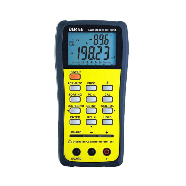
DER EE DER EE DE-5000 LCR-meter (100 kHz)
De DE-5000 is een slimme, zeer nauwkeurige, flexibele en gebruiksvriendelijke draagbare LCR-meter. Hij beschikt over automatische LCR-check, 4-draads Kelvin-meting, een backlit display met 19999 / 1999 counts, meerdere meetmodi, en instelbare testfrequenties (100 Hz, 120 Hz, 1 kHz, 10 kHz of 100 kHz). De DE-5000 LCR-meter is een handig hulpmiddel voor ingenieurs of technici. Kenmerken Automatische L.C.R. check Ls/Lp/Cs/Cp/Rs/Rp/DCR met D/Q/?/ESR meting 4-draads Kelvin-meting 19999 / 1999 counts display Achtergrondverlichting Relatieve modus Serieel/parallel modus Componenten sorteerfunctie Indicatie bij 'accu bijna leeg' Automatische power-off Specificaties Test frequentie 100 Hz / 120 Hz / 1 kHz / 10 kHz / 100 kHz Weerstand bereik 20.000 ? – 200,0 M? DCR bereik 200.00 ? – 200.0 M? Capaciteit bereik 200.00 pF – 20.00 mF Inductie bereik 20.000 ?H – 2.000 KH Display (backlit LCD-scherm) 19999 / 1999 counts Instelbare tolerantie ±0,25%, ±0,5%, ±1%, ±2%, ±5%, ±10%, ±20% Voeding 9 V accu Afmetingen 188 x 95 x 52 mm Gewicht 350 g (exclusief accu) Inbegrepen DE-5000 LCR-meter Meetconnector met krokodillenklemmen (TL-21) AC/DC-adapter Guard kabeltje (TL-23) TL-22 SMD pincetten 9 V accu Draagtas Handleiding Downloads Datasheet
€ 192,39


