
Zoekresultaten voor "raspberry OR pi OR camera OR module OR 3"
-

Elektor Digital Elektor Espressif Guest Edition (PDF)
Elektor GREEN and GOLD members can download their digital edition here. Not a member yet? Click here. Accelerating IoT Innovation A Color E-Ink Wi-Fi Picture Frame ESP-Launchpad TutorialFrom Zero to Flashing in Minutes ESP32 and ChatGPTOn the Way to a Self-Programming System… Walkie-Talkie with ESP-NOWNot Quite Wi-Fi, Not Quite Bluetooth! From Idea to Circuit with the ESP32-S3A Guide to Prototyping with Espressif Chips AIoT Chip InnovationAn Interview With Espressif CEO Teo Swee-Ann Simulate ESP32 with WokwiYour Project’s Virtual Twin Trying Out the ESP32-S3-BOX-3A Comprehensive AIoT Development Platform Electronics Workspace EssentialsInsights and Tips From Espressif Engineers The ESP RainMaker StoryHow We Built “Your” IoT Cloud Assembling the Elektor Cloc 2.0 KitAn Elektor Product Unboxed by Espressif Unleashing the ESP32-P4The Next Era of Microcontrollers Rust + EmbeddedA Development Power Duo Who Are the Rust-Dacious Embedded Developers?How Espressif is Cultivating Embedded Rust for the ESP32 Espressif’s Series of SoCs Building a PLC with Espressif SolutionsWith the Capabilities and Functionality of the ISOBUS Protocol The ESP32-S3 VGA BoardBitluni’s Exciting Journey Into Product Design Acoustic Fingerprinting on ESP32Song Recognition With Open-Source Project Olaf Circular Christmas Tree 2023A High-Tech Way to Celebrate the Holiday Season A Simpler and More Convenient LifeAn Amateur Project Based on the Espressif ESP8266 Module How to Build IoT Apps without Software ExpertiseWith Blynk IoT Platform and Espressif Hardware Building a Smart User Interface on ESP32 Quick & Easy IoT Development with M5Stack Prototyping an ESP32-Based Energy Meter A Value-Added Distributor for IoT and More In-Depth Insights: Interview With Arduino on the Nano ESP32Alessandro Ranellucci and Martino Facchin Discuss Espressif Collaboration Your AIoT Solution ProviderInsights From Espressif Streamlining MCU Development With ESP-IDF Privilege Separation An Open-Source Speech Recognition Server……and the ESP BOX The Thinking EyeFacial Recognition and More Using the ESP32-S3-EYE ESP32-C2-Based Coin Cell SwitchDesign and Performance Evaluation The Smart Home Leaps Forward with MatterUnlocking Smart Home IoT Potential Tech the Future: Where Is Smart Home IoT Headed?
€ 7,50
-

Elektor Labs Elektor Low-noise Labvoeding
De low-noise labvoeding van Elektor is een volledig analoge, instelbare, symmetrische unit met gemiddeld vermogen, zonder schakelende of digitale componenten. De uitgangsspanning is instelbaar tussen 0 V en ±22 V, en de uitgangsstroom kan worden ingesteld van 0 A tot 1 A. Doordat elke vorm van schakeltechniek wordt vermeden, levert het ontwerp extreem weinig ruis. Voor de weergave van beide uitgangsspanningen en -stromen worden vier kleine analoge paneelmeters met draaispoel gebruikt. De meeste moderne laboratoriumvoedingen en AC-adapters maken gebruik van schakelende technieken. Zelfs de beste uitvoeringen vertonen onvermijdelijk hoogfrequente rimpel en andere schakelartefacten op hun uitgang, die het testen van gevoelige analoge schakelingen kunnen verstoren en metingen van kleine signalen kunnen beïnvloeden. Om dit te voorkomen, is het concept hier een volledig analoge voeding. Hoewel deze minder efficiënt is dan vergelijkbare schakelende voedingen, is de lagere efficiëntie bij gebruik op de testbank nauwelijks van belang en zorgt deze voor schonere en betrouwbaardere meetresultaten. Omdat veel analoge schakelingen een symmetrische voeding vereisen, levert dit ontwerp positieve en negatieve uitgangsspanningen van gelijke grootte. Een kleine hoeveelheid afregeling is beschikbaar om eventuele onbalans te compenseren. Uiteraard is ook een instelbare stroombegrenzing aanwezig. De kit bevat de onderdelen die nodig zijn om de voeding te bouwen, met uitzondering van de transformatoren. Specificaties Uitgangsspanning 0…+22 V, 0, −22 V Uitgangsstroom 0…+1 A, 0…−1 A Ruis −85 dBV (bij 0,95 A/20 V, B = 22 kHz) −84 dBV (bij 0,95 A/20 V, B > 500 kHz) Rimpelspanning 50 µVRMS (bij 950 mA/20 V, B = 22 kHz, voornamelijk 100-Hz-component) Inbegrepen 3x printplaten: regelaar (PCB-1), netfilter (PCB-2) en transformator (PCB-3) Alle componenten, behalve de AC-transformatoren 4x draaispoelmeters Extra onderdelen voor de bedrading (draden, banaanstekkerbussen, IEC-voedingsmodule, enz.) Niet inbegrepen De drie AC-transformatoren Een behuizing Onderdelenlijst Voor de regelaar-printplaat (240386-1) Weerstanden (250 mW, 1%) R1 = 12 Ω R2, R8, R37, R62 = 1 MΩ R3, R7, R10, R13, R17, R20, R22, R30, R35, R42, R45, R47, R55, R60 = 100 Ω, 600 mW R4, R5 = 4.7 kΩ R6 = 100 kΩ R9, R12, R14, R36, R38, R39, R61, R63, R66, R72, R78, R79 = 10.0 kΩ, 600 mW R11 = 9.76 kΩ, 600 mW R15, R40 = 44.2 kΩ, 600 mW R16, R41, R77 = 1 kΩ R18, R43 = 1.5 kΩ, 1 W, 5% R19, R44 = 470 Ω, 1 W, 5% R21, R46 = 330 Ω, 600 mW R23, R24, R48, R49 = 1.0 Ω, 1 W R25, R50 = 1 kΩ, 1 W, 5% R26, R28, R51, R53 = 1.000 kΩ 0.1%, 15 ppm/C R27, R29, R52, R54 = 10.00 kΩ 0.1%, 15 ppm/C R31, R56 = 1.2 kΩ, 1 W, 5% R32, R57 = 47 kΩ R33, R58 = 270 Ω R34, R59 = 27 kΩ R64, R69 = 12.0 kΩ R65 = 3.0 kΩ, 600 mW R67, R80 = 470 Ω, 600 mW R68, R70 = 6.8 kΩ, 600 mW R71 = 30.0 kΩ,, 600 mW R73, R74, R75, R76 = 10 MΩ P1, P2, P3 = 10 kΩ, 200 mW, 20%, potentiometer, 1 turns, single, lin., panel mount P4, P5 = 500 Ω, 500 mW, 10%, trimmer, 25 turns, 3296Y-1-501LF Bourns P6, P7 = 10 kΩ, 500 mW, 10%, trimmer, 25 turns, 3296Y-1-501LF Bourns Condensatoren C1 = 100 nF, 50 V, 10%, ceramic X7R, LS 5 mm C2, C3, C6, C7, C30 = 10 µF, 63V, 20%, LS 2.5 mm, 3000hours@105°C C4, C5, C8, C9, C13, C14, C18, C19, C23, C24, C28, C29, C31, C32, C38, C39 = 100 nF, 250 V, 10%, PET, LS 7.5 mm C10, C20 = 47 nF, 100 V, 5%, PET, LS 5 mm C11, C21 = 10 nF, 100 V, 5%, PET, LS 5 mm C12, C22 = 220 µF, 35 V, 20%, 0.024 Ω, LS2.5/3.5 mm, Ir 3.4 A, 2000hours@125°C, polymer C15, C25 = 120 µF, 50 V, 20%, ESR 0.02 Ω, Diam. 10 mm max., LS 5 mm C16, C26 = 15 nF, 100 V, 5%, PET, LS 5 mm C17, C27 = 47 nF, 100 V, 5%, PET, LS 5 mm C33, C34 = 22 µF, 50 V, 20%, LS 2 mm, 10000 hours @ 105°C C35, C36, C44, C45 = 1 µF, 100 V, 10%, LS 5 mm, ceramic X7R C37 = 100 uF, 50 V, 20%. LS 3.5 mm C40, C41, C42, C43, C46, C47, C48, C49 = 1000 µF, 50 V, 20%, LS 5/7.5 mm, Ir 3.32 A, 10000hours@105°C, D 16 mm C50, C51, C52, C53 = 47 nF, 100 V, 10%, ceramic X7R, LS 5 mm Spoelen L1, L2 = 4.7 µH, 3.2 A, 0.033 Ω, LS 5 mm, RLB0914-4R7ML Bourns L3 = Commom mode choke, 14.5 mH, 3 A, SSRH24NH-30145 Kemet Halfgeleiders D1, D2, D3, D4, D5, D9, D10, D11, D15 = BAT85, DO-34 D6, D7, D12, D13 = SR560, DO-201AD D8, D14, D16 = 1N4148, DO-35 D17 = Zenerdiode, 5.6 V, 0.5 W, DO-41 D18, D19 = 1N4004, DO-41 D20, D21 D22, D23 = V30100CI-M3/P, dual common cathode, TO-220 D24 = Zener diode, 30 V, 1 W, DO-41 LED1, LED2 = LED, red, T-1 (3 mm) LED3, LED4 = LED, green, T-1 (3 mm) TVS1, TVS2 = BZW50-33B, R6 T1, T2, T4 = BC337.25, TO-92 T3 = NJW0302G, TO-3P T5, T6, T8 = BC327.25, TO-92 T7 = NJW0281G, TO-3P T9 = BD139, TO-126 (SOT-32) IC1 = LM334Z, TO-92 IC2 = LM4040AIZ-5.0/NOPB, TO-92 (TO-226AA-3) IC3, IC4 = OPA2992IDR, SOIC-8 IC5, IC6 = OPA4992IDR, SOIC-14 IC7 = OPA992IDBVR, SOT-23-5 IC8 = LM339N, DIP-14 IC9 = LM317, TO-220 IC10 = LM337, TO-220 Overige F1, F2 = 5×20 mm fuse, 1.6 A, fast acting HS1, HS2 = Heatsink MC33271 (for T3/T7), 2.7°C/W, PCB mount, height 63.5 mm K1, K4 = 3-way screw terminal block, LS 3.5 mm, max. 1.5 mm² K2, K3 = 3-way screw terminal block, LS 3.5 mm, max. 1 mm² M1, M3 = Moving coil meter, Range 30 V, type 91C4, 45×45 mm M2, M4 = Moving coil meter, Range 1 A, type 91C4, 45×45 mm² RE1 = Relay DPDT,5V, UA2-5NU Diversen 3× 3-way screw terminal block, LS 3.5 mm, max. 1 mm² (for P1, P2, P3) 4× Pin header, 1×2, vertical, pitch 2.54 mm (for LED1, LED2, LED3, LED4) 4× Pin socket, 1×2, vertical. pitch 2.54 mm (for LED1, LED2, LED3, LED4) 2× Heatsink FK222SA220, 20°C/W, PCB mount (for IC9 & IC10) 2× Mica thermal pad for TO-220, 12×18×0.05 mm (for IC9 & IC10) 2× Insulating bushing IB 6, TO-220 (for IC9 & IC10) 2× Ceramic thermal pad, 23×20×2 mm (for T3 & T7) 2× PCB Fuse Holder, for 5×20 mm fuse, 10 A (for F1, F2) 2× Cover for PCB Fuse Holder, transparent (for F1, F2) 2× 2-way screw terminal block, LS 3.5 mm, max. 1 mm² (for M1 & M3) 2× 2-way screw terminal block, LS 3.5 mm, max. 1.5 mm² (for M2 & M4) 8× M3 solder lug, thickness 0.35 mm (for M1…M4) M4 solder lug, thickness 0.35 mm (to connect 4 mm banana connectors) Screened cable, 1 pair, 2×24 AWG/0.22 mm², 1 m (for P1, P2 & P3) IC socket, DIP, 14 contacts (for IC8) M3 washer, plain, steel M3 screw, 16 mm, steel, pan head M3 nut M3 spring washer 50 mm M3 standoff, steel, male-female 12 mm M3 standoff, steel, male-female 10 mm M3 standoff, steel, male-female M3 screw, 8 mm, steel, pan head Voor de netfilter-printplaat (240386-2) Weerstand R1 = 220 kΩ, 1 W, 500 V, 5% Condensatoren C1, C2 = 470 nF, 305 VAC, Class X2, 11 × 27 mm max., LS 15/22.5 mm C3, C4, C5, C6 = 2.2 nF, 300 VAC, Class Y2, 13 × 4 mm, LS 10 mm, PP Spoelen L1, L2 = Common-mode choke, 6.8 mH, 1.7 A, TDK B82732R2172B030 Halfgeleider MOV1 = TVS varistor, 300 VAC, S14K300 (230 VAC, B72214S0301K101) and SK14K150 (150 VAC, B72214S0151K101) Overige K1, K2 = 3-way screw terminal block, LS 7.62 mm F1 = Time-delay fuse, 0.5 A (230 VAC) or 1 A (115 VAC) Diversen 1× Fuse holder, 5×20 mm, 10 A, 500 VAC 1× Transparent fuse cover 4× 10 mm M3 standoff, steel, male–female 4× M3 screw, 8 mm, steel, pan head 4× M3 nut Voor de transformator-printplaat (240386-3) Weerstanden R1, R2 = 2.7 kΩ, 600 mW, 1% R3 = 10.0 kΩ, 600 mW, 1% Condensator C1 = 220 µF, 50 V, 20%, Ø10 mm, LS 5 mm, 4000 h @ 105°C Transformatoren (niet inbegrepen in deze kit!) TR1, TR2, TR3 = 2×7 V, 25 VA, PCB-mounted toroid, 70060K Talema Halfgeleiders D1–D4 = 1N4148, DO-35 D5, D6 = 1N4004, DO-41 D7 = Zener 5.6 V, 1.3 W, DO-41 LED1 = LED, red, T-1 (3 mm) IC1, IC2 = MOC8021M, CTR ≥ 1000%, DIP-6 Overige F1, F2, F3 = 160 mA time-delay fuse (230 VAC) or 315 mA time-delay fuse (115 VAC) K1 = 2-way screw terminal block, LS 7.62 mm K2 = 3-way screw terminal block, LS 3.5 mm, max 1.5 mm² K3, K4 = 3-way screw terminal block, LS 3.5 mm, max 1 mm² RE1, RE2 = Relay DPDT, 5 A/250 VAC / 24 VDC Diversen 1× Pin header 1×2, pitch 2.54 mm + matching socket for LED1 3× Fuse holder 5 × 20 mm, 10 A, 500 VAC + transparent cover 3× M4 screw, 8 mm, pan head + washer for TR1-TR3 8× M3 screw, 8 mm, pan head + nut + washer 8× 10 mm M3 standoff, steel, male–female 2× IC socket, DIP-6 for IC1 & IC2 Extra onderdelen 1 m red insulated wire, stranded, 1.5 mm² 0.5 m blue insulated wire, stranded, 1.5 mm² 0.5 m black insulated wire, stranded, 1.5 mm², 0.5 m 2 m red insulated wire, stranded, D 0.56 mm (0.25 mm²) 2 m black insulated wire, stranded, D 0.56 mm (0.25 mm²) 0.5 m Multicore Cable, Flexible, 3 Core, 0.75 mm² (24 x 0.2 mm) Red banana socket Black banana socket Blue banana socket Green banana socket IEC Power Entry Module with switch, IEC C14 3 crimp terminals, FASTON, 4.75 x 0.81 mm 3 knobs Links Elektor Labs JumpStarter Page Artikel (deel 1) Artikel (deel 2)
€ 299,00€ 249,00Beste prijs
-

Elektor Digital Elektor November/December 2023 (PDF)
Elektor GREEN and GOLD members can download their digital edition here. Not a member yet? Click here. The Raspberry Pi 5A Huge Improvement From Its Predecessor AI in the Electronics LabGoogle Bard and Flux Copilot Put to the Test Arduino Nano Waveform GeneratorNano + Code = Function Generator Solar-Powered Christmas GarlandAn Eco-Friendly Solution for Garnishing Your Balcony USB Killer DetectorBetter Safe Than Sorry A Simple CNCed EnclosureWith Autodesk Fusion 360 for Personal Use Low-Volume Board ProductionWith and without Assembly IoT Simulation Simplified with WokwiDeveloper Uri Shaked on Design, Software, and More A Bare-Metal Programming Guide (Part 3)CMSIS Headers, Automatic Testing, and a Web Server LoRa, a Swiss Army Knife (2)The Hardware and Software MEMS Microphone Design and Construction Tools to Try Before You SolderSimulation and 3D Modeling Tools That Can Be Used for Free New Tools From Microchip!PICkit 5 and MPLAB ICD 5 Available Now! Rapid Prototyping of Flexible, Stretchable ElectronicsHow the Voltera NOVA Speeds Up Innovation in Wearable Electronic Systems Galvanic IsolationUsing Phototransistor Optocouplers Successfully The Complex Solution or the Anybus Solution?Embedded Industrial Ethernet in 2 Days Rather Than Many Months Your Essential DFM ChecklistHow to Start Designing for Manufacture 3D Printing FilamentsTypes, Features and Use in Prototyping Specialists for Effective Signal Analysis from ELF to EHF BandAaronia’s latest real-time SPECTRAN® V6 series spectrum analyzers Challenges of DFM Analysis for Flex and Rigid-Flex Design Setting Up an SMT Line The Right Combination for a Reliable Assembly Revolutionizing IndustriesThe Rise of Autonomous Mobile Robots (AMRs) Evolved for More ChallengesRohde & Schwarz Adds Eight-Channel R&S MXO 5 to Next-Generation Oscilloscopes Starting Out in Electronics……Amplifying Differences Mini Reflow PlateFor Assembling or Repairing Small SMD Circuits Don’t Start with a Prototype – Start with a Pretotype!Check That a Market Exists for Your Product Before Warming Your Soldering Iron 2023: An AI OdysseyGetting Help Designing a Physical Project Brussels Is InnovatingSupport for Deep Tech
€ 7,50
-
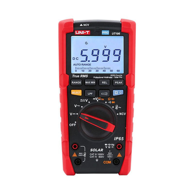
Uni-Trend UNI-T UT196 True RMS Solar Multimeter
De UT196 True RMS Solar multimeter is een ideaal hulpmiddel bij het onderhoud van zonne-energie systemen. Deze robuuste meter is ontworpen voor technici die in weer en wind buiten werken. De UT196 kan spanning meten tot 1700 V DC en 1500 V AC, en stroom tot 3000 A AC met behulp van een externe stroomtangsensor. Deze solar meter is waterdicht conform IP65, en is ook bestand tegen een val van 2 m. De UT196 Solar multimeter is ontworpen met beveiligingen tegen overbelasting van 1700 V DC en 1500 Vrms AC, en getest voor veilig gebruik in CAT III 1000 V en CAT IV 600 V omgevingen. Kenmerken True RMS Meet tot 1700 V DC en 1500 V AC bij hoogspanningstoepassingen zoals zonnepanelen en wind Bescherming conform IP65 CAT III 1000V, CAT IV 600 V Analoge staafgrafiek Frequentiebereik: 45 Hz~1 kHz Laagdoorlaatfilter functie Modus voor lage impedantie Ingebouwde zaklamp, heldere achtergrondverlichting, en visueel alarm Toepassingen Meten van hoge DC-spanningen Uitgangsspanning- en frequentiemeting Spannings- en frequentiemeting Stroom- en frequentiemeting Specificaties Bereik UT196 DC-spanning (V) 1700 V ±0,2% +5 AC-spanning (V) 1500 V ±0,8% +3 Frequentie (Hz) 1 MHz ±0,08% +4 Weerstand (?) 60 M? ±0,8% +2 Capaciteit (F) 60 mF ±1,9% +5 Voeding 9 V batterij Afmetingen 195 x 95 x 58 mm Inbegrepen UT196 Solar multimeter Batterij Meetsnoeren Downloads Datasheet Gebruikershandleiding
€ 129,63
-

Siglent Siglent SSA3032X Plus Spectrum Analyzer (9 kHz - 3,2 GHz)
De Siglent SSA3032X Plus spectrum analyzer is een krachtig en flexibel hulpmiddel voor RF signaal- en netwerkanalyse. Met een frequentiebereik van 3,2 GHz levert de analyzer betrouwbare automatische metingen en meerdere werkingsmodi: spectrum analyzer als basisfunctie, en optionele functies als RF-vermogensmeting, vectorsignaal-modulatieanalyse, reflectiemeting en EMI-test.Toepassingen zijn onder meer monitoring/evaluatie van zendsignalen, metingen op locatie, S-parameter meting, analoge/digitale modulatie analyse, EMI pre-compliance test, onderzoek en ontwikkeling, onderwijs, productie en onderhoud.Kenmerken Spectrum analyzer frequentiebereik van 9 kHz tot 3,2 GHz –161 dBm/Hz Displayed Average Noise Level (typ.) –98 dBc/Hz. @ 10 kHz Offset Phase Noise (1 GHz, typ.) Level Measurement Uncertainty< 0,7 dB (typ.) 1 Hz minimale Resolution Bandwidth (RBW) Voorversterker (standaard) Tracking generator (inbegrepen, gratis) Analoge en digitale signaalmodulatie-analyse modus (optioneel) Reflectie meetkit (optioneel) EMI filter en quasi-peak detector kit (optioneel) Advanced Measurement Kit (optioneel) 10,1-inch multi-touch scherm, muis en toetsenbord ondersteund Webbrowser afstandsbediening op pc en mobiele terminals, en bediening via files Specificaties SSA3015X Plus SSA3021X Plus SSA3032X Plus SSA3075X Plus Frequentiebereik 9 kHz ~ 1,5 GHz 9 kHz ~ 2,1 GHz 9 kHz ~ 3,2 GHz 9 kHz ~ 7,5 GHz Resolutie bandbreedte 1 Hz ~ 1 MHz 1 Hz ~ 1 MHz 1 Hz ~ 1 MHz 1 Hz ~ 3 MHz Phase Noise <–99 dBc/Hz <–98 dBc/Hz <–98 dBc/Hz <–98 dBc/Hz Total Amplitude Accuracy < 1,2 dB < 0,7 dB < 0,7 dB < 0,7 dB Display Average Noise Level –156 dBm/Hz –161 dBm/Hz –161 dBm/Hz –165 dBm/Hz Inbegrepen Siglent SSA3032X Plus spectrum analyzer USB kabel Netsnoer Quick Start gids Downloads Datasheet Manual Documentation Firmware
€ 2.951,19
-

Elektor Digital Elektor Juillet/Août 2022 (PDF)
Testeur audio à prix modéré Et avec une base logique sur PC et une interface audio USB Fréquencemètre secteur CA Contrôler la fréquence et la tension du secteur Inductancemètre très simple Une tenue facile à porter Lévitation avec ondes acoustiques Un aperçu du kit de lévitation acoustique de Makerfabs Démarrer en électronique? Les redresseurs E-FFWD : regardons à nouveau vers l'avenir ! Débutant avec son oscilloscope Suivez le guide pour parcourir les boutons et molettes Radio logique MSF utilisant un Raspberry Pi Pico Décodeur à signal temporel à logique radio (SDR) basé sur le RPi Pico Capteurs d'humidité pour systèmes d'arrosage Arrosage automatique Nouvelle donne dans les instruments de test et mesure L'innovation des petits acteurs Infographie 07-08/2022 L?inspiration, c?est ça qui compte Entretien avec Walter Arkesteijn, l'entreprise InnoFaith Beauty Sciences et lecteur d'Elektor Minimiser les interférences CEM même avec le stockage Création d'interfaces graphiques et Python avec guide : Jeu de Morpion Relais Reed Drôles de composants ESR-mètre analogique simple et précis en galvanomètre en cadre mobile Feu tricolore pour CO2, connecté à Sigfox N'oubliez pas de vérifier le WiFi ! Femmes de technologie « On juge au mérite, jusqu'à ce que le mérite ait des seins. » Tablette oscilloscope ADS1013D à petit prix Bon rapport qualité/prix ? Dissection des prix intelligents Lesquelles peut-on ouvrir ? Impédance et capacité de la peau Petites expériences Sur le vif Nul n'est prophète en son pays Prise en main du Pokit Meter Couteau suisse pour la mesure Hexadoku Casse-tête pour électriciens
€ 10,95
-

Rigol Rigol DG2052 Function/Arbitrary Waveform Generator (50 MHz)
Highlights Output Frequency (Sine): 50 MHz Output Frequency (Square): 15 MHz Channels: 2 Arbitrary Waveform Length: 16 Mpts Kenmerken Unique SiFi II (Signal Fidelity II) technology: generate the arbitrary waveforms point by point; recover the signal without distortion; sample rate accurate and adjustable; jitter of all the output waveforms (including Sine, Pulse, etc.) as low as 200 ps 16 Mpts memory depth per channel for arbitrary waveforms Standard dual-channel with the same performance, equivalent to two independent signal sources High frequency stability: ±1 ppm; low phase noise: -105 dBc/Hz Built-in high-order harmonic generator (at most 8-order harmonics) Built-in 7 digits/s, 240 MHz bandwidth full featured frequency counter Up to 160 built-in arbitrary waveforms, covering the common signals in engineering application, medical electronics, auto electronics, math processing, and other various fields Sample rate up to 250 MSa/s, vertical resolution 16 bits Arbitrary waveform sequence editing function available; arbitrary waveforms also can be generated through the PC software Various analog and digital modulation functions: AM, FM, PM, ASK, FSK, PSK, and PWM. Standard waveform combine function, capable of outputting specified waveforms combined with the basic waveforms Standard channel tracking function, when enabled, all the parameters of both channels are updated based on users' configurations Standard interface: USB Host&Device and LAN (LXI Core 2011 Device); USB-GPIB function supported 4.3'' TFT Inbegrepen 1x Rigol DG2052 Function/Arbitrary Waveform Generator 1x Power cord 1x USB cable
€ 652,19
-

Elektor 07-08/2026 (DE)
Diese Ausgabe steht allen GOLD- und GREEN-Mitgliedern auf der ElektorMagazine-Website zum Download bereit! Sie sind noch kein Mitglied? Hier klicken! MultiRF-EntwicklungsboardEine Plattform zur Evaluierung drahtloser Protokolle für kurze und lange Reichweiten Elektor wird 65Elektronik im Wandel seit 1961 WLAN-basierte Personenerkennung mit dem ESP32Wenn der Router zum Bewegungsmelder wird Drahtlose WaagenVier kleine Waagen = eine große Waage Walter, das kompakte IoT-ModulESP32-S3-SoC, LTE-M/NB-IoT-5G-Modem und GNSS-Receiver 3- und 4-Draht-RTD-Sensoren konditionierenMit Vollbereichsabgleich und Kabelkompensation Drei in einem: 2-Kanal-Oszilloskop/Generator/MultimeterEin Test des Fnirsi 2D15P electronica Fast Forward 2026 für Start-ups und Industriepartner EcologgingEine modulare IoT-Messstation für Umweltdaten Drahtlos-Anbindung für MedizingeräteImmer am Puls mit Bluetooth LE AudiotronicsBrummunterdrückung Mehr Effizienz in der Landwirtschaft durch KI-Modelle und SensorenSteigerung der landwirtschaftlichen Produktivität OPC UA – ein ÜberblickPlattformunabhängiger Datenaustausch Redox-Meter Instrumentenverstärker für Physik- und Engineering-Experimente Aktive differentielle Audio-FilterFür professionelle Frequenzweichen und mehr Elektor-Community-Tipps zu IoT und Sensoren Telegram-gesteuerter WarmwasserbereiterEine Lösung mit ESP32 und Arduino-Software 2026: Eine KI-OdysseeWas wurde eigentlich aus der Fuzzy-Logik? Projekt 2.0 Alarmsignalinjektor + PowerTools zum Suchen verdeckt verlegter Leitungen
€ 15,90
-

Elektor Digital Elektor 11-12/2021 (PDF)
NVIDIA JETSON NANO - BILDVERARBEITUNG FÜR EINSTEIGER (TEIL 2)Erkennen von Objekten mit Edge Impulse ELEKTOR JUMPSTARTER-NEWSKommende Kampagnen OPEN-SOURCE-GPS-TRACKING-PLATTFORMFahrzeug-Tracking ohne fremde Cloud mit Traccar MULTIFUNKTIONS-KOMPONENTENTESTER LCR-T7 VON JOY-ITTesten von passiven Bauteilen, diskreten Halbleitern und IR-Fernbedienungen RAUSCH-SYNTHESIZERVom Rauschen zur Musik mit dem PRBSynth1 ALLER ANFANG …ist gar nicht schwer! Weiter geht's mit der Spule... DIE NEURONEN IN NEURONALEN NETZEN VERSTEHENTeil 2: Logische Neuronen BLITZLICHT-GESCHÜTZTER ANALOGSPEICHER-ZUSATZ FÜR DAS MANIPULATIONSSICHERE DATENPAKETProbleme mit der Sicherheit? Bekämpfen Sie Feuer mit Feuer! LCR METER POSTER BLUETOOTH-BEACONS IN DER PRAXISOrtsbestimmung in Innenräumen C-PROGRAMMIERUNG AUF RASPBERRY PIEin Beispielkapitel: Kommunizieren über WLAN EMV-VORKONFORMITÄTSTEST FÜR IHR DC-VERSORGTES PROJEKTTeil 2: Die Hardware und wie man sie benutzt PARALLAX PROPELLER 2Teil 5: Das Innenleben des Smart Pins MODBUS ÜBER WLANTeil 1: Hardware und Programmierung ZUTRITT FÜR UNBEFUGTE VERBOTENWie der Junior-Computer wieder zum Leben erweckt wurde BAUEN SIE IHREN EIGENEN HOCHPRÄZISIONSKALIBRATOR-10 V bis +10 V, 0 bis 40 mA, 0,001% ARDUINO NANO RP2040 CONNECTRaspberry Pi RP2040 + WLAN + Bluetooth DER PHYSISCHE KÖRPER DER KÜNSTLICHEN INTELLIGENZ PROJEKT 2.0Korrekturen, Updates und Leserbriefe GRAFISCHE BENUTZEROBERFLÄCHEN MIT PYTHON UND GUIZERO CO2-MESSGERÄT-SET FÜRS KLASSENZIMMEREin ESP8266-basiertes Gerät, entwickelt von der FH Aachen NOSTALGISCHES MW/LW-RADIO MIT MK484...macht immer Spaß zu bauen! 60 JAHRE ELEKTOREs werde Licht! HEXADOKUThe Original Elektorized Sudoku
€ 11,90
-
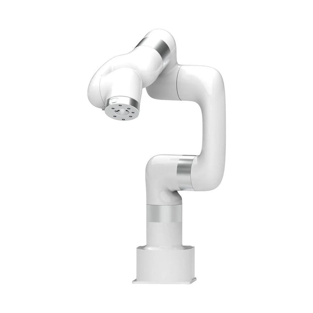
UFactory UFactory xArm 5 Lite
This multi-axis robot perfectly balances power and size. Features 5 Axis Payload: 3 kg Reach: 700 mm Repeatability: 0.1 mm Max Speed 1000 mm/s Applications Machine Tending Bin Picking Mobile platform Lab Automation Robotic Research Durable Collaborative robots for your automation Industrial-grade harmonic drive and servomotors guarantee 24/7 working without stop. Crafted from Carbon fiber, 15 kg weight makes it possible for easier deployment. Flexible deployment with safe feature Hand teaching, lightweight, space-saving and easy to re-deploy to multiple applications without changing your production layout. Perfectly for recurrent tasks. Collision detection is available for all of our cobots. Your safety is always the top priority. Graphical interface for beginner-friendly programming Compatible with various of operation systems, including macOS and Windows. Web-based technology compatible with all major browsers. Drag and drop to create your code in minutes. Powerful and open source SDK at your fingertips Fully functional open-source Python/C++ SDK provides more flexible programming. ROS/ROS2 packages are ready-to-go. Example codes help you to deploy the robotic arm smoothly. Specifications UFactory 850 xArm 5 xArm 6 xArm 7 Payload 5 kg 3 kg 5 kg 3.5 kg Reach 850 mm 700 mm 700 mm 700 mm Degrees of freedom 6 5 6 7 Repeatability ±0.02 mm ±0.1 mm ±0.1 mm ±0.1 mm Maximum Speed 1 m/s 1 m/s 1 m/s 1 m/s Weight (robot arm only) 20 kg 11.2 kg 12.2 kg 13.7 kg Maximum Speed 180°/s 180°/s 180°/s 180°/s Joint 1 ±360° ±360° ±360° ±360° Joint 2 -132°?132° -118°?120° -118°?120° -118°?120° Joint 3 -242°~3.5° -225°~11° -225°~11° ±360° Joint 4 ±360° -97°~180° ±360° -11°?225° Joint 5 -124°~124° ±360° -97°~180° ±360° Joint 6 ±360° ±360° -97°~180° Joint 7 ±360° Hardware Ambient Temperature Range 0-50°C Power Consumption Min 8.4 W, Typical 200 W, max 400 W Input Power Supply 24 V DC, 16.5 A Footprint Ø 126 mm Materials Aluminum, Carbon Fiber Base Connector Type M5x5 ISO Class Cleanroom 5 Robot Mounting Any End Effector Communication Protocol Modbus RTU(rs485) End Effector I/O 2x DI/2x DO/2x AI/1x RS485 Communication Mode Ethernet Included 1x xArm 5 robotic arm 1x AC control box 1x Robotic arm power cable 1x Robotic arm end effector adapter cable 1x Robotic arm signal cable 1x Control box power cable 1x Network cable 1x Mounting tool 1x Quick start guide
€ 7.285,00
Beste prijs
-

Elektor Edge Impulse Guest Edition 2025 (FR)
Le téléchargement intégral de ce numéro est disponible pour nos membres GOLD et GREEN sur le site Elektor Magazine ! Pas encore membre ? Cliquez ici. qu’est-ce que l’edge AI ?L’IA, intégrée à l’appareil découvrez Edge Impulse StudioConcevez et déployez facilement des modèles d’IA en périphérie détection de mots-clés avec Edge ImpulseCollecter, entraîner et déployer contrôle d’appareils par commande vocale avec le Nordic Thingy:53 Termes clés pour comprendre l’edge AI et le machine learning cours accéléré : démarrez avec Edge ImpulseApprenez à collecter, entraîner et déployer un modèle ML avec l’Arduino Nano 33 BLE Sense un nouveau chapitre pour ArduinoD’une carte pour amateurs à une plateforme d’edge computing premiers pas avec la détection d’objets sur des appareils edge détection de défauts sur circuits imprimésVision par ordinateur avec Raspberry Pi adapter l’IA aux appareils les plus compacts optimiser l’efficacité énergétique des appareils edge AI alimentés sur batterie grille-pain intelligentL’IA qui reconnaît le toast parfait Thundercomm Rubik Pi 3Raspberry Pi et l’edge AI, enfin réunis Leadership, ML embarqué et révolution de l’IA en périphérie modèles vision-langage en périphérieCascade de modèles pour une meilleure fiabilité découvrez Edge ImpulseQuestions de la communauté Elektor mise à jour du projet n°5 : Compteur d’énergie ESP32Utiliser l’Edge AI pour identifier les charges domestiques reconnaissance de mouvements avec détection d’anomaliesUn tutoriel détaillé système de ventilation intelligent : fusion des données sonores et environnementalesUtilisation d’un microcontrôleur double-cœur et du ML pour l’automatisation des fenêtres et persiennes intégrer la commande vocale aux écouteurs et aux casques l'IA en périphérie : au cœur des appareils de demain
€ 16,50
-
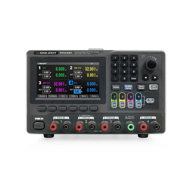
Siglent Siglent SPD4306X 4-kanaals Voeding (400 W)
The Siglent SPD4306X is a 4-channel DC Linear Programmable Power Supply equipped with a 4.3-inch TFT-LCD display, friendly human-machine interface, and excellent performance indicators. Real-time waveform display provides engineers with an informative user interface. SPD4306X offers a total output power of 400 W with a resolution of 1 mV/1 mA. The maximum voltage and current for each channel are as follows: CH1: 15 V/1.5 A CH2: 30 V/6 A CH3: 30 V/6 A CH4: 15 V/1 A Kenmerken Rated output power: 400 W Rated voltage: 32 V, 12 V, 30 V Up to four high-precision power supplies with independent controllable outputs, supporting CH2 and CH3 series and parallel connections Clear graphical interface with waveform and timer display modes 5-digit voltage and current display with minimum resolution of 1 mV, 1 mA Fast output response time: <50us The high current channel support remote voltage compensation sense function. The maximum compensation voltage is 0.6 V Overvoltage protection and overcurrent protection or safe and accurate operation Equipped with a 4.3-inch TFT-LCD display (480 x 272 resolution) USB and LAN standard communication USB-GPIB module is optional Excellent channel density with up to 4 channels in a 3U half rack package Internal data storage for setups and parameters Embedded Web Server with instrument communication that doesn’t require software installation Fully SCPI programming command set support as well as a LabView driver for remote control and system automation Specificaties SPD4323X SPD4121X SPD4306X Channel Output CH1: Voltage 0 to 6 V Current 0 to 3.2 ACH2: Voltage 0 to 32 V Current 0 to 3.2 ACH3: Voltage 0 to 32 V Current 0 to 3.2 ACH4: Voltage 0 to 6 V Current 0 to 3.2 A CH1: Voltage 0 to 15 V Current 0 to 1.5 ACH2: Voltage 0 to 12 V Current 0 to 10 ACH3: Voltage 0 to 12 V Current 0 to 10 ACH4: Voltage 0 to 15 V Current 0 to 1.5 A CH1: Voltage 0 to 15 V Current 0 to 1.5 ACH2: Voltage 0 to 30 V Current 0 to 6 ACH3: Voltage 0 to 30 V Current 0 to 6 ACH4: Voltage 0 to 15 V Current 0 to 1 A Resolution 1 mV, 1 mA 1 mV, 1 mA 1 mV, 1 mA Setting Accuracy Voltage: ±(0.03% of reading+10) mV, Current: ±(0.3% of reading+10) mA Voltage: ±(0.03% of reading+10) mV, Current: ±(0.3% of reading+10) mA Voltage: ±(0.03% of reading+10) mV, Current: ±(0.3% of reading+10) mA Readback Accuracy Voltage: ±(0.03% of reading+10) mV, Current: ±(0.3% of reading+10) mA Voltage: ±(0.03% of reading+10) mV, Current: ±(0.3% of reading+10) mA Voltage: ±(0.03% of reading+10) mV, Current: ±(0.3% of reading+10) mA Display 4.3" TFT-LCD 5-digit voltage and current display 4.3" TFT-LCD 5-digit voltage and current display 4.3" TFT-LCD 5-digit voltage and current display Output power 240 W 285 W 400 W Inbegrepen 1x Siglent SPD4306X Power Supply 1x Power cord (EU) 1x Output test cord (3 A) 1x USB cable 1x Quick start guide Downloads Datasheet Manual Quick start
€ 1.101,10


