
Zoekresultaten voor "elektor OR archive OR 1974 OR 2023 OR usb OR stick OR en"
-

Elecrow Elecrow ThinkNode M5 – Meshtastic LoRa-transceiver (868 MHz)
Hoogwaardig LoRa-communicatieapparaat De Elecrow ThinkNode M5 is een compact, draagbaar LoRa-communicatieapparaat dat is ontworpen voor berichtenverkeer en het delen van locaties buiten het bereik van mobiele netwerken (off-grid) en voor gebruik in de buitenlucht. Het apparaat wordt aangestuurd door een ESP32-S3-processor en een SX1262 LoRa-chip, is voorzien van vooraf geïnstalleerde Meshtastic-firmware en kan eenvoudig via Bluetooth worden geconfigureerd met de officiële Meshtastic-app. De geïntegreerde multi-GNSS-module ondersteunt GPS, GLONASS, BeiDou en QZSS voor betrouwbare positionering en het delen van locaties. Berichten en apparaatgegevens worden weergegeven op het energiezuinige 1,54-inch e-paper-scherm, terwijl de ingebouwde oplaadbare accu van 1.200 mAh zorgt voor langdurig mobiel gebruik. Dankzij de geïntegreerde LoRa-antenne, de compacte behuizing, de RTC en de ondersteuning voor zowel Meshtastic- als MeshCore-firmware is de ThinkNode M5 een praktische communicatieoplossing voor wandelen, kamperen, afgelegen locaties en noodsituaties waarin conventionele mobiele netwerken niet beschikbaar zijn. Kenmerken LoRa-communicatie Multi-GNSS-positionering Oplaadbare accu van 1200 mAh 1,54-inch e-paper-display Ingebouwde RTC Compatibel met MeshCore Compatibel met Meshtastic Specificaties Hoofdprocessor (ESP32-S3) CPU/SoC Xtensa 32-bit LX7 dual-core processor, geklokt op maximaal 240 MHz Systeemgeheugen 512 KB SRAM, 8 MB PSRAM Opslag 4 MB Flash, 384 KB ROM Firmware Volledig compatibel met Meshtastic-firmware; signaaloverdracht via LoRa-modus EPD (Electronic Paper Display) Displaygrootte 1,54-inch EPD (monochroom E-Ink-scherm) Displaymateriaal E-Ink (Electronic Ink) Resolutie 200 x 200 Driver-chip SSD1681 (via SPI- of I²C-interface) Volledige verversingstijd 2 s Draadloze communicatie Bluetooth Bluetooth Low Energy en Bluetooth 5.0 (configuratie via telefoon) LoRa SX1262 LoRa-module, EU 868 MHz (externe antenne) Hardware Interfaces USB-C, RP-SMA Functies GPS-locatie (GPS, GLONASS, BeiDou, QZSS), EPD-scherm, RTC, USB 2.0, PMU-energiebeheer (ingebouwde 1200 mAh-lithiumaccu), zoemer, enz. Knoppen Draaischakelaar, functieknop, paginaknop, GPS-schakelaar, resetknop LED-indicator Voeding, GPS/LoRa-indicatie Overige Voeding 5 V/1 A, ondersteunt voeding via USB of lithiumbatterij Stroomverbruik De maximale bedrijfsstroom bedraagt ongeveer 340 mA (CPU + LoRa-module); het verbruik in de energiezuinige modus bedraagt ongeveer 34 uA Bedrijfstemperatuur -10~50°C Opslagtemperatuur -20~60°C Relatieve luchtvochtigheid 10-95% bij 40°C (niet-condenserend) Behuizing ABS-kunststof Afmetingen 82 x 51,6 x 26,3 mm Gewicht 81 g Inbegrepen 1x Elecrow ThinkNode M5 1x LoRa-antenne 1x USB-C kabel 1x Manual Downloads Manual
€ 74,95
Leden: € 67,46
-

Elektor Publishing Professional SMD Assembly
Practical Low-Cost Methods for Reliable PCB Production This book explains how to carry out reliable SMD assembly using affordable tools and small-scale equipment. It follows the complete workflow step by step, including tool selection, solder paste handling, stencil use, component placement, reflow methods, inspection, and rework. The focus is on bench-level and small-lab production rather than industrial assembly lines. It shows practical methods for building single and double-sided SMD boards with repeatable results. Topics include solder paste and flux, temperature profiles, hot air and hotplate techniques, small reflow ovens, inspection methods, and defect correction. Checklists and example workflows are included to help reduce errors and improve consistency. Key features: Tools and supplies for SMD assembly and rework Solder paste types, storage, and handling Stencils and paste application methods Pick and place workflow and component orientation Temperature profiles and reflow methods Hot air, hotplate, and reflow oven processes Inspection and quality control Common defects such as tombstoning and solder bridges Practical rework and component replacement Bench-level professional workflows and checklists This book is designed as a practical bench reference for anyone who wants to assemble and troubleshoot their own SMD boards with reliable results.
€ 24,95
Leden: € 22,46
-

Great Scott Gadgets Great Scott Gadgets HackRF Pro SDR (100 kHz – 6 GHz) + GRATIS e-book
ACTIE: Bestel de HackRF Pro nu en ontvang het nieuwe e-book "SDR with HackRF One & HackRF Pro" ter waarde van € 20 gratis! HackRF Pro is de nieuwste Software Defined Radio (SDR) van Great Scott Gadgets en de krachtige opvolger van de legendarische HackRF One. Met een frequentiebereik van 100 kHz tot 6 GHz bestrijkt het een enorm spectrum voor het verzenden en ontvangen van radiosignalen. Ontworpen als een open-source hardwareplatform, is de HackRF Pro de ideale tool voor het analyseren en ontwikkelen van moderne draadloze technologieën. Het kan flexibel worden gebruikt als USB-randapparaat of worden geprogrammeerd voor zelfstandig (standalone) gebruik. Specificaties Frequentie: 100 kHz tot 6 GHz Instelbaar van 0 Hz tot 7,1 GHz Half-duplex transceiver Tot 20 miljoen samples per seconde 8-bits kwadratuur-samples (8-bits I en 8-bits Q) Compatibel met GNU Radio, SDR# en meer Softwarematig configureerbare RX- en TX-versterking en basisbandfilter Softwarematig geregelde RF-poortvoeding (50 mA bij 3,3 V) SMA RF-connector SMA-klokingang en -uitgang voor synchronisatie en triggering Handige knoppen voor programmering Interne pinheaders voor uitbreiding High-Speed USB 2.0 met USB-C connector Voeding via USB Open source hardware In vergelijking met zijn voorganger, biedt HackRF Pro een aantal nieuwe functies, waaronder: Breder werkfrequentiebereik Verbeterde RF-prestaties met een vlakkere frequentierespons USB-C-connector Ingebouwde TCXO-kristaloscillator voor superieure timingstabiliteit Logica-upgrade van een CPLD naar een energiezuinige FPGA Eliminatie van de DC-piek Uitgebreide precisie-modus met 16-bits samples voor lage samplefrequenties (typische ENOB: 9-11) Halfprecisie-modus met 4-bits samples tot 40 Msps Meer RAM en flashgeheugen voor aangepaste firmware Afscherming rond het radiogedeelte Trigger-ingang en -uitgang toegankelijk via klokconnectoren Uitsparing in de printplaat biedt ruimte voor toekomstige uitbreidingen add-ons Verbeterd energiebeheer Verbeterde bescherming van de RF-poort Mogelijkheid om de zendmodus hardwarematig uit te schakelen Volledige compatibiliteit: Dankzij de beproefde architectuur kan bestaande software voor de HackRF One ook direct worden gebruikt met de HackRF Pro. De HackRF Pro biedt naadloze achterwaartse compatibiliteit en tegelijkertijd aanzienlijk verbeterde prestaties. Let op: Een antenne is niet inbegrepen. Wij raden de ANT500 aan voor een optimale start. Inbegrepen HackRF Pro SDR met kunststofbehuizing Nieuw e-book: SDR with HackRF One & HackRF Pro (normale prijs: € 20) Downloads Documentation GitHub
€ 489,00€ 429,00Beste prijs
-

FNIRSI 65 W USB-C PD GaN Voeding
Met deze 65 W USB-C PD voeding (met GaN technologie) kunt u de FNIRSI HS-01 soldeerbout direct gebruiken. Natuurlijk kunt u deze lader ook gebruiken om uw tablets en smartphones snel op te laden via USB-C en USB-A. Inbegrepen 65 W USB-C PD GaN Voeding (EU)
€ 25,00
-

Red Pitaya Red Pitaya STEMlab 125-14 PRO Gen 2 Starter Kit (incl. Boek)
Deze bundel bevat de Red Pitaya STEMlab 125-14 PRO Gen 2 Starter Kit en het nieuwe boek "Experimenteren met Red Pitaya STEMlab Gen 2". De Red Pitaya STEMlab 125-14 PRO Gen 2 Starter Kit is een krachtig en flexibel platform voor signaalverwerking, data-acquisitie en elektronische meettoepassingen. Deze kit is ontworpen voor ingenieurs, ontwikkelaars, onderzoekers en docenten en biedt alles wat nodig is om te beginnen met het bouwen van geavanceerde meet- en besturingssystemen. De kern van de kit wordt gevormd door het STEMlab 125-14 PRO Gen 2-bord, een geüpgradede en ultralichte ontwikkeling. Aangedreven door de Xilinx Zynq-7010 SoC met 512 MB RAM, combineert het de programmeerbaarheid van een FPGA met de verwerkingskracht van een ARM-processor om hoogwaardige instrumentatie en aangepaste signaalverwerkingsoplossingen mogelijk te maken. Het bord biedt een 14-bits ADC- en DAC-resolutie, een bemonsteringsfrequentie van 125 MS/s, een ingangsbereik van ±20 V en een bandbreedte tot 60 MHz. Dankzij de verbeterde ruisarme analoge front-end, USB-C-connectiviteit en het compacte ontwerp is het geschikt voor veeleisende toepassingen zoals RF-ontwikkeling, radarsystemen, fotonica-onderzoek, softwaregedefinieerde radio (SDR) en industriële automatisering. De Starter Kit bevat alle essentiële accessoires voor onmiddellijk gebruik: een microSD-kaart met vooraf geïnstalleerd besturingssysteem, voeding, ethernetkabel voor toegang op afstand, twee 100 MHz-oscilloscoopprobes en SMA-naar-BNC-adapters voor flexibele signaalaansluitingen. De Red Pitaya STEMlab 125-14 PRO Gen 2 Starter Kit is een uitstekend platform voor rapid prototyping, FPGA-ontwikkeling, meetinstrumentatie en geavanceerde elektronica-experimenten. Kenmerken 14-bits ADC- en DAC-resolutie 125 MS/s samplingfrequentie ±20 V ingangsbereik Tot 60 MHz bandbreedte Xilinx Zynq-7010 SoC (FPGA + ARM-processor) 512 MB RAM Ruisarme analoge front- en back-ends Toepassingen RF-ontwikkeling en -testen Radar- en draadloze systemen Software Defined Radio (SDR) Fotonica en optisch onderzoek Industriële automatisering en besturingssystemen Signaalanalyse en instrumentatie Snel prototypen van elektronische meetsystemen Specificaties Processor Dual-core ARM Cortex-A9 FPGA AMD Xilinx Zynq-7010 SoC RAM 512 MB (4 Gb) Opslag microSD-kaart (tot 32 GB) Besturingssysteem Linux-gebaseerd Red Pitaya OS ADC-resolutie 14-bits DAC Resolutie 14-bits Bandbreedte 60 MHz (DC) Sampling rate 125 MS/s Analoge ingangskanalen 2 Analoge uitgangskanalen 2 Ingangsspanningsbereik ±1 V (LV) / ±20 V (HV) Ingangsimpedantie 1 MΩ / 10 pF Uitgangsspanningsbereik ±1 V Ethernet 1x Gigabit Ethernet (RJ45) USB 2x USB-C 2.0 (voor voeding en console) Digitale I/O 16x GPIO (3,3 V) Communicatie-interfaces I²C, SPI, UART, CAN Voeding 5 V/3 A via USB-C Afmetingen 106,8 x 60,0 x 17,9 mm Inbegrepen 1x Red Pitaya STEMlab 125-14 PRO Gen 2 Board 2x 100 MHz oscilloscoopprobes 2x SMA-naar-BNC-adapters 1x microSD-kaart met voorgeïnstalleerd besturingssysteem 1x USB-C-voeding 1x Ethernetkabel Downloads Documentation Schematics Book: Experimenting with Red Pitaya STEMlab Gen 2 Met dit nieuwe boek gaat Red Pitaya verder dan een veelzijdig board. Het wordt een krachtig laboratoriuminstrument voor nauwkeurige metingen, analyse en besturing. Van de basisprincipes van elektronische projectontwikkeling, monitoring, besturing en ontwerp tot testen: dit boek begeleidt u stap voor stap door alles wat u moet weten om het volledige potentieel van de Red Pitaya-hardware en -software te benutten. Het boek presenteert real-time, FPGA-gebaseerde projecten die op een PC worden ontwikkeld met de Vivado-omgeving en vervolgens naar de Red Pitaya worden overgebracht voor uitvoering en testen. U leert over verbeterde prestaties, uitgebreide I/O-mogelijkheden, verbeterde FPGA-functionaliteiten en geavanceerde connectiviteitsopties die nieuwe mogelijkheden openen voor nauwkeurige metingen, monitoring en besturing in uw embedded toepassingen. In dit boek ontdekt u: Een diepgaande verkenning van de Red Pitaya-architectuur en het hardwareontwerp Elektronische experimenten met Red Pitaya voor meting en monitoring Praktische projecten met de programmeertaal Python Praktische richtlijnen voor FPGA-programmering met Red Pitaya Red Pitaya FPGA-projecten met Verilog HDL in de Vivado IDE Praktisch ontwerp van elektronische projecten inclusief meting en testen Stapsgewijze voorbeelden die theorie en praktijk met elkaar verbinden Of u nu uw eigen elektronische schakelingen ontwerpt, tools voor signaalanalyse ontwikkelt of real-time besturings- of monitoringssystemen creëert, dit boek biedt u de kennis en het vertrouwen om het Red Pitaya-platform volledig te leren kennen en aan te passen.
€ 799,00
Beste prijs
-
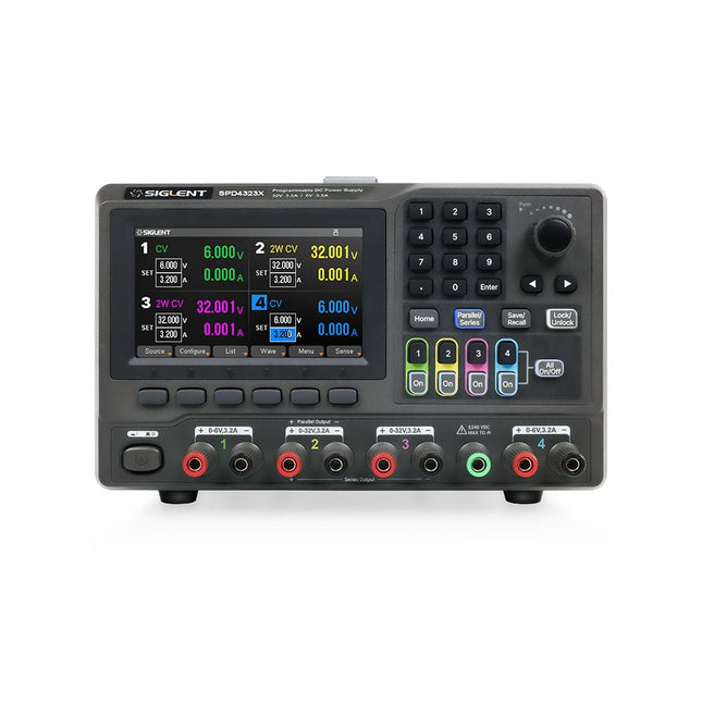
Siglent Siglent SPD4323X 4-kanaals Voeding (240 W)
The Siglent SPD4323X is a 4-channel DC Linear Programmable Power Supply equipped with a 4.3-inch TFT-LCD display, friendly human-machine interface, and excellent performance indicators. Real-time waveform display provides engineers with an informative user interface. SPD4323X offers a total output power of 240 W with a resolution of 1 mV/1 mA. The maximum voltage and current for each channel are as follows: CH1: 6 V/3.2 A CH2: 32 V/3.2 A CH3: 32 V/3.2 A CH4: 6 V/3.2 A Kenmerken Rated output power: 240 W Rated voltage: 32 V, 12 V, 30 V Up to four high-precision power supplies with independent controllable outputs, supporting CH2 and CH3 series and parallel connections Clear graphical interface with waveform and timer display modes 5-digit voltage and current display with minimum resolution of 1 mV, 1 mA Fast output response time: <50us The high current channel support remote voltage compensation sense function. The maximum compensation voltage is 0.6 V Overvoltage protection and overcurrent protection or safe and accurate operation Equipped with a 4.3-inch TFT-LCD display (480 x 272 resolution) USB and LAN standard communication USB-GPIB module is optional Excellent channel density with up to 4 channels in a 3U half rack package Internal data storage for setups and parameters Embedded Web Server with instrument communication that doesn’t require software installation Fully SCPI programming command set support as well as a LabView driver for remote control and system automation Specificaties SPD4323X SPD4121X SPD4306X Channel Output CH1: Voltage 0 to 6 V Current 0 to 3.2 ACH2: Voltage 0 to 32 V Current 0 to 3.2 ACH3: Voltage 0 to 32 V Current 0 to 3.2 ACH4: Voltage 0 to 6 V Current 0 to 3.2 A CH1: Voltage 0 to 15 V Current 0 to 1.5 ACH2: Voltage 0 to 12 V Current 0 to 10 ACH3: Voltage 0 to 12 V Current 0 to 10 ACH4: Voltage 0 to 15 V Current 0 to 1.5 A CH1: Voltage 0 to 15 V Current 0 to 1.5 ACH2: Voltage 0 to 30 V Current 0 to 6 ACH3: Voltage 0 to 30 V Current 0 to 6 ACH4: Voltage 0 to 15 V Current 0 to 1 A Resolution 1 mV, 1 mA 1 mV, 1 mA 1 mV, 1 mA Setting Accuracy Voltage: ±(0.03% of reading+10) mV, Current: ±(0.3% of reading+10) mA Voltage: ±(0.03% of reading+10) mV, Current: ±(0.3% of reading+10) mA Voltage: ±(0.03% of reading+10) mV, Current: ±(0.3% of reading+10) mA Readback Accuracy Voltage: ±(0.03% of reading+10) mV, Current: ±(0.3% of reading+10) mA Voltage: ±(0.03% of reading+10) mV, Current: ±(0.3% of reading+10) mA Voltage: ±(0.03% of reading+10) mV, Current: ±(0.3% of reading+10) mA Display 4.3" TFT-LCD 5-digit voltage and current display 4.3" TFT-LCD 5-digit voltage and current display 4.3" TFT-LCD 5-digit voltage and current display Output power 240 W 285 W 400 W Inbegrepen 1x Siglent SPD4323X Power Supply 1x Power cord (EU) 1x Output test cord (3 A) 1x USB cable 1x Quick start guide Downloads Datasheet Manual Quick start
€ 762,30
-
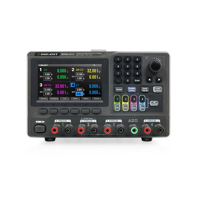
Siglent Siglent SPD4121X 4-kanaals Voeding (285 W)
The Siglent SPD4121X is a 4-channel DC Linear Programmable Power Supply equipped with a 4.3-inch TFT-LCD display, friendly human-machine interface, and excellent performance indicators. Real-time waveform display provides engineers with an informative user interface. SPD4121X offers a total output power of 285 W with a resolution of 1 mV/1 mA. The maximum voltage and current for each channel are as follows: CH1: 15 V/1.5 A CH2: 12 V/10 A CH3: 12 V/10 A CH4: 15 V/1.5 A Kenmerken Rated output power: 285 W Rated voltage: 32 V, 12 V, 30 V Up to four high-precision power supplies with independent controllable outputs, supporting CH2 and CH3 series and parallel connections Clear graphical interface with waveform and timer display modes 5-digit voltage and current display with minimum resolution of 1 mV, 1 mA Fast output response time: <50us The high current channel support remote voltage compensation sense function. The maximum compensation voltage is 0.6 V Overvoltage protection and overcurrent protection or safe and accurate operation Equipped with a 4.3-inch TFT-LCD display (480 x 272 resolution) USB and LAN standard communication USB-GPIB module is optional Excellent channel density with up to 4 channels in a 3U half rack package Internal data storage for setups and parameters Embedded Web Server with instrument communication that doesn’t require software installation Fully SCPI programming command set support as well as a LabView driver for remote control and system automation Specificaties SPD4323X SPD4121X SPD4306X Channel Output CH1: Voltage 0 to 6 V Current 0 to 3.2 ACH2: Voltage 0 to 32 V Current 0 to 3.2 ACH3: Voltage 0 to 32 V Current 0 to 3.2 ACH4: Voltage 0 to 6 V Current 0 to 3.2 A CH1: Voltage 0 to 15 V Current 0 to 1.5 ACH2: Voltage 0 to 12 V Current 0 to 10 ACH3: Voltage 0 to 12 V Current 0 to 10 ACH4: Voltage 0 to 15 V Current 0 to 1.5 A CH1: Voltage 0 to 15 V Current 0 to 1.5 ACH2: Voltage 0 to 30 V Current 0 to 6 ACH3: Voltage 0 to 30 V Current 0 to 6 ACH4: Voltage 0 to 15 V Current 0 to 1 A Resolution 1 mV, 1 mA 1 mV, 1 mA 1 mV, 1 mA Setting Accuracy Voltage: ±(0.03% of reading+10) mV, Current: ±(0.3% of reading+10) mA Voltage: ±(0.03% of reading+10) mV, Current: ±(0.3% of reading+10) mA Voltage: ±(0.03% of reading+10) mV, Current: ±(0.3% of reading+10) mA Readback Accuracy Voltage: ±(0.03% of reading+10) mV, Current: ±(0.3% of reading+10) mA Voltage: ±(0.03% of reading+10) mV, Current: ±(0.3% of reading+10) mA Voltage: ±(0.03% of reading+10) mV, Current: ±(0.3% of reading+10) mA Display 4.3" TFT-LCD 5-digit voltage and current display 4.3" TFT-LCD 5-digit voltage and current display 4.3" TFT-LCD 5-digit voltage and current display Output power 240 W 285 W 400 W Inbegrepen 1x Siglent SPD4121X Power Supply 1x Power cord (EU) 1x Output test cord (3 A) 1x USB cable 1x Quick start guide Downloads Datasheet Manual Quick start
€ 871,20
-
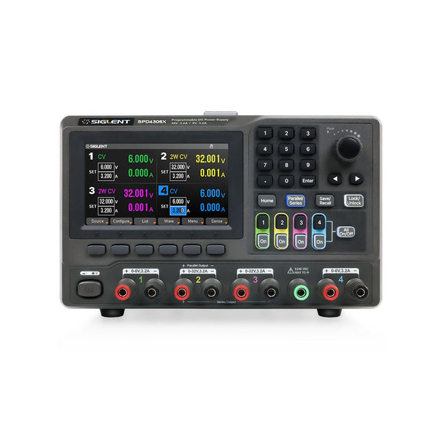
Siglent Siglent SPD4306X 4-kanaals Voeding (400 W)
The Siglent SPD4306X is a 4-channel DC Linear Programmable Power Supply equipped with a 4.3-inch TFT-LCD display, friendly human-machine interface, and excellent performance indicators. Real-time waveform display provides engineers with an informative user interface. SPD4306X offers a total output power of 400 W with a resolution of 1 mV/1 mA. The maximum voltage and current for each channel are as follows: CH1: 15 V/1.5 A CH2: 30 V/6 A CH3: 30 V/6 A CH4: 15 V/1 A Kenmerken Rated output power: 400 W Rated voltage: 32 V, 12 V, 30 V Up to four high-precision power supplies with independent controllable outputs, supporting CH2 and CH3 series and parallel connections Clear graphical interface with waveform and timer display modes 5-digit voltage and current display with minimum resolution of 1 mV, 1 mA Fast output response time: <50us The high current channel support remote voltage compensation sense function. The maximum compensation voltage is 0.6 V Overvoltage protection and overcurrent protection or safe and accurate operation Equipped with a 4.3-inch TFT-LCD display (480 x 272 resolution) USB and LAN standard communication USB-GPIB module is optional Excellent channel density with up to 4 channels in a 3U half rack package Internal data storage for setups and parameters Embedded Web Server with instrument communication that doesn’t require software installation Fully SCPI programming command set support as well as a LabView driver for remote control and system automation Specificaties SPD4323X SPD4121X SPD4306X Channel Output CH1: Voltage 0 to 6 V Current 0 to 3.2 ACH2: Voltage 0 to 32 V Current 0 to 3.2 ACH3: Voltage 0 to 32 V Current 0 to 3.2 ACH4: Voltage 0 to 6 V Current 0 to 3.2 A CH1: Voltage 0 to 15 V Current 0 to 1.5 ACH2: Voltage 0 to 12 V Current 0 to 10 ACH3: Voltage 0 to 12 V Current 0 to 10 ACH4: Voltage 0 to 15 V Current 0 to 1.5 A CH1: Voltage 0 to 15 V Current 0 to 1.5 ACH2: Voltage 0 to 30 V Current 0 to 6 ACH3: Voltage 0 to 30 V Current 0 to 6 ACH4: Voltage 0 to 15 V Current 0 to 1 A Resolution 1 mV, 1 mA 1 mV, 1 mA 1 mV, 1 mA Setting Accuracy Voltage: ±(0.03% of reading+10) mV, Current: ±(0.3% of reading+10) mA Voltage: ±(0.03% of reading+10) mV, Current: ±(0.3% of reading+10) mA Voltage: ±(0.03% of reading+10) mV, Current: ±(0.3% of reading+10) mA Readback Accuracy Voltage: ±(0.03% of reading+10) mV, Current: ±(0.3% of reading+10) mA Voltage: ±(0.03% of reading+10) mV, Current: ±(0.3% of reading+10) mA Voltage: ±(0.03% of reading+10) mV, Current: ±(0.3% of reading+10) mA Display 4.3" TFT-LCD 5-digit voltage and current display 4.3" TFT-LCD 5-digit voltage and current display 4.3" TFT-LCD 5-digit voltage and current display Output power 240 W 285 W 400 W Inbegrepen 1x Siglent SPD4306X Power Supply 1x Power cord (EU) 1x Output test cord (3 A) 1x USB cable 1x Quick start guide Downloads Datasheet Manual Quick start
€ 1.101,10
-

Elektor Digital Programming Microcontrollers in MicroPython (E-book)
With Examples for Raspberry Pi Pico and ESP32 Creating and programming small electronic systems is now easier than ever before. With inexpensive development boards and modern software tools, anyone curious about embedded design can quickly move from an idea to a working piece of hardware. At the heart of this change is MicroPython—a clear, interactive, and beginner-friendly way to program microcontrollers while still remaining closely connected to the underlying electronics. This book introduces embedded programming through MicroPython on popular platforms such as the Raspberry Pi Pico and the ESP32. You will discover how to use microcontrollers for reading inputs, processing data, and controlling outputs in a predictable, real-time loop. With just a few lines of code, you can blink LEDs, read sensors, drive motors, and communicate with the outside world. The interactive REPL programming interface encourages experimentation and fast learning, making concepts tangible from the very first chapter. While different boards offer different capabilities, they all share the same core principles. Timers, GPIO, analog I/O, PWM, interrupts, and communication interfaces form the foundation of every embedded system. By focusing on these universal building blocks, this book helps you build skills that transfer across platforms and scale naturally toward more advanced development. Whether you are a beginner or an experienced programmer entering embedded systems, you will find that working with MicroPython is both practical and genuinely enjoyable.
€ 24,95
Leden: € 22,46
-

NXP Semiconductors NXP FRDM-MCXN947 Development Board
The FRDM-MCXN947 is a compact and versatile development board designed for rapid prototyping with MCX N94 and N54 microcontrollers. It features industry-standard headers for easy access to the MCU's I/Os, integrated open-standard serial interfaces, external flash memory, and an onboard MCU-Link debugger. Specificaties Microcontroller MCX-N947 Dual Arm Cortex-M33 cores @ 150 MHz each with optimized performance efficiency, up to 2 MB dual-bank flash with optional full ECC RAM, External flash Accelerators: Neural Processing Unit, PowerQuad, Smart DMA, etc. Memory Expansion *DNP Micro SD card socket Connectivity Ethernet Phy and connector HS USB-C connectors SPI/I²C/UART connector (PMOD/mikroBUS, DNP) WiFi connector (PMOD/mikroBUS, DNP) CAN-FD transceiver Debug On-board MCU-Link debugger with CMSIS-DAP JTAG/SWD connector Sensor P3T1755 I³C/I²C Temp Sensor, Touch Pad Expansion Options Arduino Header (with FRDM expansion rows) FRDM Header FlexIO/LCD Header SmartDMA/Camera Header Pmod *DNP mikroBUS User Interface RGB user LED, plus Reset, ISP, Wakeup buttons Inbegrepen 1x FRDM-MCXN947 Development Board 1x USB-C Cable 1x Quick Start Guide Downloads Datasheet Block diagram
-
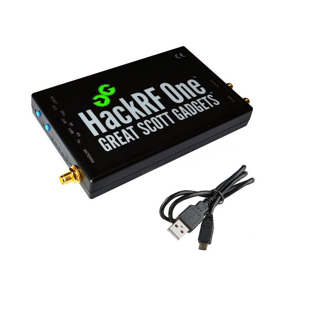
Great Scott Gadgets Great Scott Gadgets HackRF One SDR (1 MHz – 6 GHz)
Nieuwe versie beschikbaar! Klik hier! HackRF One is een Software Defined Radio (SDR) instrument dat radiosignalen van 1 MHz tot 6 GHz kan verzenden of ontvangen. Het is ontworpen om evaluatie en de ontwikkeling van moderne en nieuwe radio technologien mogelijk te maken. HackRF One is een open source hardwareplatform dat kan worden gebruikt als een USB-randapparaat of kan worden geprogrammeerd voor stand-alone gebruik. Specificaties 1 MHz tot 6 GHz werkfrequentie Half-duplex transceiver Tot 20 miljoen samples per seconde 8-bits quadrature samples (8-bits I en 8-bits Q) Compatibel met GNU Radio, SDR en meer Software-configureerbare RX- en TX-versterking en baseband filter Softwaregestuurde antennepoortvoeding (50 mA bij 3,3 V) SMA female antenne connector SMA female clock input en output voor synchronisatie Handige programmeerbare knoppen Interne pin-headers voor uitbreiding Hi-Speed USB 2.0 USB-voeding Open source-hardware HackRF One is een testapparaat voor RF-systemen. Het is niet getest op naleving van de voorschriften voor het verzenden van radiosignalen. U bent verantwoordelijk voor het legaal gebruiken van de HackRF One. Inbegrepen 1x HackRF One SDR 1x Kunststof behuizing 1x micro-USB-kabel Let op: er wordt geen antenne meegeleverd. ANT500 wordt aanbevolen als antenne voor HackRF One voor starters. Downloads Documentatie GitHub Broncode en hardwareontwerpbestanden
-
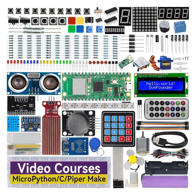
SunFounder SunFounder Kepler Kit (Ultimate Starter Kit voor Raspberry Pi Pico W)
Uw toegangspoort tot IoT en programmeren met microcontrollers Met 450+ componenten en 117 online projecten, stimuleert deze uitgebreide kit uw creativiteit. De tutorials van Paul McWhorter maken leren leuk voor beginners en gevorderde gebruikers. Deze kit ondersteunt MicroPython, C/C++ en Piper Make, en biedt diverse programmeeropties. Ontdek sensoren, actuatoren, LED's en LCD's voor eindeloze projectmogelijkheden. Van huisautomatisering tot robotica, deze kit versterkt uw technische reis. Kenmerken IoT Starter Kit voor beginners: Deze kit biedt een rijke IoT-leerervaring voor beginners. Met 450+ componenten, 117 projecten en door experts geleide videolessen, maakt deze kit het leren van microcontrollerprogrammering en IoT boeiend en toegankelijk. Door experts geleide videolessen: De kit bevat 27 videotutorials van de bekende docent Paul McWhorter. Zijn boeiende stijl vereenvoudigt complexe concepten, wat zorgt voor een effectieve leerervaring in microcontrollerprogrammering. Breed scala aan hardware: De kit bevat een divers scala aan componenten zoals sensoren, actuatoren, LED's, LCD's en meer, waardoor u kunt experimenteren en verschillende projecten kunt maken met de Raspberry Pi Pico W. Ondersteunt meerdere talen: De kit biedt veelzijdigheid met ondersteuning voor drie programmeertalen – MicroPython, C/C++ en Piper Make, wat zorgt voor een gevarieerde programmeerleerervaring. Toegewijde ondersteuning: Profiteer van onze voortdurende assistentie, inclusief een communityforum en tijdige technische hulp voor een naadloze leerervaring. Inbegrepen Raspberry Pi Pico W Breadboard Jumper Wires Weerstand Transistor Condensator Diode Li-po-oplaadmodule 74HC595 TA6586 – Motordriverchip LED RGB-LED LED-staafdiagram Weergave met 7 segmenten 4-cijferige 7-segmentweergave LED-dotmatrix I²C LCD1602 WS2812 RGB-strip met 8 LED's Zoemer DC-motor Servo DC-water Pomp Relais Knop Microschakelaar Schuifschakelaar Potentiometer Infraroodontvanger Joystickmodule 4x4 toetsenbord MPR121-module MFRC522-module Fotoweerstand Thermistor Kantelschakelaar Reedschakelaar PIR-bewegingssensormodule Waterniveausensormodule Ultrasone module DHT11-vochtigheidssensor MPU6050-module Documentatie Online tutorials in 3 talen (EN, DE en JP)


