ARM Cortex-M Embedded Design from 0 to 1
Hobbyists can mash together amazing functional systems using platforms like Arduino or Raspberry Pi, but it is imperative that engineers and product designers understand the foundational knowledge of embedded design. There are very few resources available that describe the thinking, strategies, and processes to take an idea through hardware design and low-level driver development, and successfully build a complete embedded system. Many engineers end up learning the hard way, or never really learn at all.
ARM processors are essentially ubiquitous in embedded systems. Design engineers building novel devices must understand the fundamentals of these systems and be able to break down large, complicated ideas into manageable pieces. Successful product development means traversing a huge amount of documentation to understand how to accomplish what you need, then put everything together to create a robust system that will reliably operate and be maintainable for years to come.
This book is a case study in embedded design including discussion of the hardware, processor initialization, low‑level driver development, and application interface design for a product. Though we describe this through a specific application of a Cortex-M3 development board, our mission is to help the reader build foundational skills critical to being an excellent product developer. The completed development board is available to maximize the impact of this book, and the working platform that you create can then be used as a base for further development and learning.
The Embedded in Embedded program is about teaching fundamental skill sets to help engineers build a solid foundation of knowledge that can be applied in any design environment. With nearly 20 years of experience in the industry, the author communicates the critical skill development that is demanded by companies and essential to successful design. This book is as much about building a great design process, critical thinking, and even social considerations important to developers as it is about technical hardware and firmware design.
Downloads
EiE Software Archive (200 MB)
IAR ARM 8.10.1 (Recommended IDE version to use) (1.2 GB)
IAR ARM 7.20.1 (Optional IDE version to use) (600 MB)
Hoogwaardig LoRa-communicatieapparaat
De Elecrow ThinkNode M5 is een compact, draagbaar LoRa-communicatieapparaat dat is ontworpen voor berichtenverkeer en het delen van locaties buiten het bereik van mobiele netwerken (off-grid) en voor gebruik in de buitenlucht. Het apparaat wordt aangestuurd door een ESP32-S3-processor en een SX1262 LoRa-chip, is voorzien van vooraf geïnstalleerde Meshtastic-firmware en kan eenvoudig via Bluetooth worden geconfigureerd met de officiële Meshtastic-app.
De geïntegreerde multi-GNSS-module ondersteunt GPS, GLONASS, BeiDou en QZSS voor betrouwbare positionering en het delen van locaties. Berichten en apparaatgegevens worden weergegeven op het energiezuinige 1,54-inch e-paper-scherm, terwijl de ingebouwde oplaadbare accu van 1.200 mAh zorgt voor langdurig mobiel gebruik.
Dankzij de geïntegreerde LoRa-antenne, de compacte behuizing, de RTC en de ondersteuning voor zowel Meshtastic- als MeshCore-firmware is de ThinkNode M5 een praktische communicatieoplossing voor wandelen, kamperen, afgelegen locaties en noodsituaties waarin conventionele mobiele netwerken niet beschikbaar zijn.
Kenmerken
LoRa-communicatie
Multi-GNSS-positionering
Oplaadbare accu van 1200 mAh
1,54-inch e-paper-display
Ingebouwde RTC
Compatibel met MeshCore
Compatibel met Meshtastic
Specificaties
Hoofdprocessor (ESP32-S3)
CPU/SoC
Xtensa 32-bit LX7 dual-core processor, geklokt op maximaal 240 MHz
Systeemgeheugen
512 KB SRAM, 8 MB PSRAM
Opslag
4 MB Flash, 384 KB ROM
Firmware
Volledig compatibel met Meshtastic-firmware; signaaloverdracht via LoRa-modus
EPD (Electronic Paper Display)
Displaygrootte
1,54-inch EPD (monochroom E-Ink-scherm)
Displaymateriaal
E-Ink (Electronic Ink)
Resolutie
200 x 200
Driver-chip
SSD1681 (via SPI- of I²C-interface)
Volledige verversingstijd
2 s
Draadloze communicatie
Bluetooth
Bluetooth Low Energy en Bluetooth 5.0 (configuratie via telefoon)
LoRa
SX1262 LoRa-module, EU 868 MHz (externe antenne)
Hardware
Interfaces
USB-C, RP-SMA
Functies
GPS-locatie (GPS, GLONASS, BeiDou, QZSS), EPD-scherm, RTC, USB 2.0, PMU-energiebeheer (ingebouwde 1200 mAh-lithiumaccu), zoemer, enz.
Knoppen
Draaischakelaar, functieknop, paginaknop, GPS-schakelaar, resetknop
LED-indicator
Voeding, GPS/LoRa-indicatie
Overige
Voeding
5 V/1 A, ondersteunt voeding via USB of lithiumbatterij
Stroomverbruik
De maximale bedrijfsstroom bedraagt ongeveer 340 mA (CPU + LoRa-module); het verbruik in de energiezuinige modus bedraagt ongeveer 34 uA
Bedrijfstemperatuur
-10~50°C
Opslagtemperatuur
-20~60°C
Relatieve luchtvochtigheid
10-95% bij 40°C (niet-condenserend)
Behuizing
ABS-kunststof
Afmetingen
82 x 51,6 x 26,3 mm
Gewicht
81 g
Inbegrepen
1x Elecrow ThinkNode M5
1x LoRa-antenne
1x USB-C kabel
1x Manual
Downloads
Manual
Deze complete microcontroller-programmeercursus op basis van de Raspberry Pi Pico bevat een leerboek, een componentenkit, praktische projecten en een uitgebreide online cursus met simulaties. Ideaal om embedded systems stap voor stap te leren programmeren in MicroPython via een praktische hands-on aanpak.
Een praktische introductie tot embedded systems met de Raspberry Pi Pico
Deze cursus is ontworpen voor beginners in embedded systems die op zoek zijn naar een gestructureerde en voorbeeldgerichte start.
Een kit met LED’s en weerstanden, schakelaars, sensoren en actuatoren, displays, een breadboard en draden is inbegrepen. Deze worden in de cursus gebruikt om voorbeeldtoepassingen te demonstreren.
Er is geen voorkennis van Arduino of embedded ontwikkeling vereist. Elke sectie bevat praktische voorbeelden en mini-projecten om belangrijke concepten te versterken en verdere verkenning te stimuleren. Aan het einde van de cursus kunt u niet alleen de voorbeelden reproduceren, maar ook uitbreiden met uw eigen ideeën en toepassingen.
Wat leert u?
Microcontrollerprogrammering in MicroPython met de Raspberry Pi Pico met behulp van de Thonny IDE
Werken met digitale I/O, knoppen en encoders uitlezen, LED’s en relais aansturen
Analoge ingangen, spanningen en sensoren uitlezen
Genereren van analoge uitgangssignalen en PWM
Gebruik van seriële communicatie zoals UART, I²C en SPI om displays aan te sturen en digitale sensoren en SD-kaarten uit te lezen
Tijdbeheer
Werken met interrupts
Realtime sensorinput en besturing via knoppen, LED’s en displays
Aansturen van actuatoren zoals relais en servomotoren
Voor wie is dit?
Studenten en zelflerenden die embedded systems willen ontdekken
Makers en IoT-enthousiastelingen die hun hardwarevaardigheden willen verbeteren
Docenten en trainers die kant-en-klaar lesmateriaal zoeken
Wat zit er in de doos?
Toegang tot de volledige cursus op het Elektor Academy Pro leerplatform
Raspberry Pi Pico microcontrollerboard + USB-kabel
Boek: Programming Microcontrollers in MicroPython
Downloadbare projectbestanden voor elke module
Componentenkit:
2× LED, rood, 5 mm
LED, groen, 5 mm
3× weerstand, 470 Ω, 0,25 W
LDR
Potentiometer, 10 kΩ, lineair
Drukknop
Rotary encoder module
Relaismodule
DHT22 temperatuur- en vochtigheidssensor
TM1637-compatibel 4-digit 7-segment display
MPU-6050 IMU met headers
SSD1306-compatibel I²C OLED display
Micro SD-kaartadapter met header
Buzzer
SG90 micro servo
ILI9341-compatibel SPI 240×320 TFT display
20× jumper wires
Breadboard
Alle programmeercursussen (en verschillen in inhoud)
Cursus
Arduino
Raspberry Pi Pico with Arduino C/C++
ESP32 with Arduino C/C++
Raspberry Pi Pico with MicroPython
ESP32 with MicroPython
Online cursus
Access to Arduino Course
Access to Pico with Arduino C/C++ Course
Access to ESP32 with Arduino C/C++ Course
Access to Pico with MicroPython Course
Access to ESP32 with MicroPython Course
Board
Uno R3
Raspberry Pi Pico
ESP32
Raspberry Pi Pico
ESP32
Boek
Programming Microcontrollers in C/C++ Using Arduino
Programming Microcontrollers in C/C++ Using Arduino
Programming Microcontrollers in C/C++ Using Arduino
Programming Microcontrollers in MicroPython
Programming Microcontrollers in MicroPython
Kit
40-delige componenten-kit
40-delige componenten-kit
40-delige componenten-kit
40-delige componenten-kit
40-delige componenten-kit
Met deze 65 W USB-C PD voeding (met GaN technologie) kunt u de FNIRSI HS-01 soldeerbout direct gebruiken. Natuurlijk kunt u deze lader ook gebruiken om uw tablets en smartphones snel op te laden via USB-C en USB-A.
Inbegrepen
65 W USB-C PD GaN Voeding (EU)
Deze bundel bevat de Red Pitaya STEMlab 125-14 PRO Gen 2 Starter Kit en het nieuwe boek "Experimenteren met Red Pitaya STEMlab Gen 2".
De Red Pitaya STEMlab 125-14 PRO Gen 2 Starter Kit is een krachtig en flexibel platform voor signaalverwerking, data-acquisitie en elektronische meettoepassingen. Deze kit is ontworpen voor ingenieurs, ontwikkelaars, onderzoekers en docenten en biedt alles wat nodig is om te beginnen met het bouwen van geavanceerde meet- en besturingssystemen.
De kern van de kit wordt gevormd door het STEMlab 125-14 PRO Gen 2-bord, een geüpgradede en ultralichte ontwikkeling. Aangedreven door de Xilinx Zynq-7010 SoC met 512 MB RAM, combineert het de programmeerbaarheid van een FPGA met de verwerkingskracht van een ARM-processor om hoogwaardige instrumentatie en aangepaste signaalverwerkingsoplossingen mogelijk te maken.
Het bord biedt een 14-bits ADC- en DAC-resolutie, een bemonsteringsfrequentie van 125 MS/s, een ingangsbereik van ±20 V en een bandbreedte tot 60 MHz. Dankzij de verbeterde ruisarme analoge front-end, USB-C-connectiviteit en het compacte ontwerp is het geschikt voor veeleisende toepassingen zoals RF-ontwikkeling, radarsystemen, fotonica-onderzoek, softwaregedefinieerde radio (SDR) en industriële automatisering.
De Starter Kit bevat alle essentiële accessoires voor onmiddellijk gebruik: een microSD-kaart met vooraf geïnstalleerd besturingssysteem, voeding, ethernetkabel voor toegang op afstand, twee 100 MHz-oscilloscoopprobes en SMA-naar-BNC-adapters voor flexibele signaalaansluitingen.
De Red Pitaya STEMlab 125-14 PRO Gen 2 Starter Kit is een uitstekend platform voor rapid prototyping, FPGA-ontwikkeling, meetinstrumentatie en geavanceerde elektronica-experimenten.
Kenmerken
14-bits ADC- en DAC-resolutie
125 MS/s samplingfrequentie
±20 V ingangsbereik
Tot 60 MHz bandbreedte
Xilinx Zynq-7010 SoC (FPGA + ARM-processor)
512 MB RAM
Ruisarme analoge front- en back-ends
Toepassingen
RF-ontwikkeling en -testen
Radar- en draadloze systemen
Software Defined Radio (SDR)
Fotonica en optisch onderzoek
Industriële automatisering en besturingssystemen
Signaalanalyse en instrumentatie
Snel prototypen van elektronische meetsystemen
Specificaties
Processor
Dual-core ARM Cortex-A9
FPGA
AMD Xilinx Zynq-7010 SoC
RAM
512 MB (4 Gb)
Opslag
microSD-kaart (tot 32 GB)
Besturingssysteem
Linux-gebaseerd Red Pitaya OS
ADC-resolutie
14-bits
DAC Resolutie
14-bits
Bandbreedte
60 MHz (DC)
Sampling rate
125 MS/s
Analoge ingangskanalen
2
Analoge uitgangskanalen
2
Ingangsspanningsbereik
±1 V (LV) / ±20 V (HV)
Ingangsimpedantie
1 MΩ / 10 pF
Uitgangsspanningsbereik
±1 V
Ethernet
1x Gigabit Ethernet (RJ45)
USB
2x USB-C 2.0 (voor voeding en console)
Digitale I/O
16x GPIO (3,3 V)
Communicatie-interfaces
I²C, SPI, UART, CAN
Voeding
5 V/3 A via USB-C
Afmetingen
106,8 x 60,0 x 17,9 mm
Inbegrepen
1x Red Pitaya STEMlab 125-14 PRO Gen 2 Board
2x 100 MHz oscilloscoopprobes
2x SMA-naar-BNC-adapters
1x microSD-kaart met voorgeïnstalleerd besturingssysteem
1x USB-C-voeding
1x Ethernetkabel
Downloads
Documentation
Schematics
Book: Experimenting with Red Pitaya STEMlab Gen 2
Met dit nieuwe boek gaat Red Pitaya verder dan een veelzijdig board. Het wordt een krachtig laboratoriuminstrument voor nauwkeurige metingen, analyse en besturing.
Van de basisprincipes van elektronische projectontwikkeling, monitoring, besturing en ontwerp tot testen: dit boek begeleidt u stap voor stap door alles wat u moet weten om het volledige potentieel van de Red Pitaya-hardware en -software te benutten.
Het boek presenteert real-time, FPGA-gebaseerde projecten die op een PC worden ontwikkeld met de Vivado-omgeving en vervolgens naar de Red Pitaya worden overgebracht voor uitvoering en testen.
U leert over verbeterde prestaties, uitgebreide I/O-mogelijkheden, verbeterde FPGA-functionaliteiten en geavanceerde connectiviteitsopties die nieuwe mogelijkheden openen voor nauwkeurige metingen, monitoring en besturing in uw embedded toepassingen.
In dit boek ontdekt u:
Een diepgaande verkenning van de Red Pitaya-architectuur en het hardwareontwerp
Elektronische experimenten met Red Pitaya voor meting en monitoring
Praktische projecten met de programmeertaal Python
Praktische richtlijnen voor FPGA-programmering met Red Pitaya
Red Pitaya FPGA-projecten met Verilog HDL in de Vivado IDE
Praktisch ontwerp van elektronische projecten inclusief meting en testen
Stapsgewijze voorbeelden die theorie en praktijk met elkaar verbinden
Of u nu uw eigen elektronische schakelingen ontwerpt, tools voor signaalanalyse ontwikkelt of real-time besturings- of monitoringssystemen creëert, dit boek biedt u de kennis en het vertrouwen om het Red Pitaya-platform volledig te leren kennen en aan te passen.
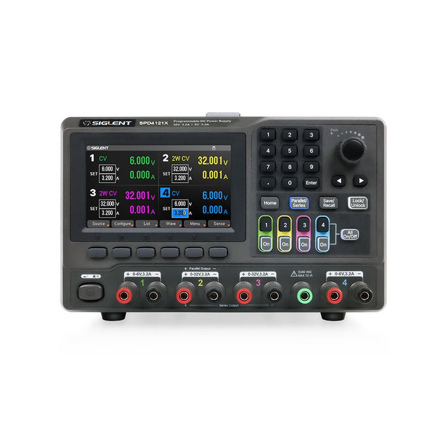
The Siglent SPD4121X is a 4-channel DC Linear Programmable Power Supply equipped with a 4.3-inch TFT-LCD display, friendly human-machine interface, and excellent performance indicators. Real-time waveform display provides engineers with an informative user interface.
SPD4121X offers a total output power of 285 W with a resolution of 1 mV/1 mA. The maximum voltage and current for each channel are as follows:
CH1: 15 V/1.5 A
CH2: 12 V/10 A
CH3: 12 V/10 A
CH4: 15 V/1.5 A
Kenmerken
Rated output power: 285 W
Rated voltage: 32 V, 12 V, 30 V
Up to four high-precision power supplies with independent controllable outputs, supporting CH2 and CH3 series and parallel connections
Clear graphical interface with waveform and timer display modes
5-digit voltage and current display with minimum resolution of 1 mV, 1 mA
Fast output response time: <50us
The high current channel support remote voltage compensation sense function. The maximum compensation voltage is 0.6 V
Overvoltage protection and overcurrent protection or safe and accurate operation
Equipped with a 4.3-inch TFT-LCD display (480 x 272 resolution)
USB and LAN standard communication
USB-GPIB module is optional
Excellent channel density with up to 4 channels in a 3U half rack package
Internal data storage for setups and parameters
Embedded Web Server with instrument communication that doesn’t require software installation
Fully SCPI programming command set support as well as a LabView driver for remote control and system automation
Specificaties
SPD4323X
SPD4121X
SPD4306X
Channel Output
CH1: Voltage 0 to 6 V Current 0 to 3.2 ACH2: Voltage 0 to 32 V Current 0 to 3.2 ACH3: Voltage 0 to 32 V Current 0 to 3.2 ACH4: Voltage 0 to 6 V Current 0 to 3.2 A
CH1: Voltage 0 to 15 V Current 0 to 1.5 ACH2: Voltage 0 to 12 V Current 0 to 10 ACH3: Voltage 0 to 12 V Current 0 to 10 ACH4: Voltage 0 to 15 V Current 0 to 1.5 A
CH1: Voltage 0 to 15 V Current 0 to 1.5 ACH2: Voltage 0 to 30 V Current 0 to 6 ACH3: Voltage 0 to 30 V Current 0 to 6 ACH4: Voltage 0 to 15 V Current 0 to 1 A
Resolution
1 mV, 1 mA
1 mV, 1 mA
1 mV, 1 mA
Setting Accuracy
Voltage: ±(0.03% of reading+10) mV, Current: ±(0.3% of reading+10) mA
Voltage: ±(0.03% of reading+10) mV, Current: ±(0.3% of reading+10) mA
Voltage: ±(0.03% of reading+10) mV, Current: ±(0.3% of reading+10) mA
Readback Accuracy
Voltage: ±(0.03% of reading+10) mV, Current: ±(0.3% of reading+10) mA
Voltage: ±(0.03% of reading+10) mV, Current: ±(0.3% of reading+10) mA
Voltage: ±(0.03% of reading+10) mV, Current: ±(0.3% of reading+10) mA
Display
4.3" TFT-LCD 5-digit voltage and current display
4.3" TFT-LCD 5-digit voltage and current display
4.3" TFT-LCD 5-digit voltage and current display
Output power
240 W
285 W
400 W
Inbegrepen
1x Siglent SPD4121X Power Supply
1x Power cord (EU)
1x Output test cord (3 A)
1x USB cable
1x Quick start guide
Downloads
Datasheet
Manual
Quick start
De MDP-P906 heeft een ingebouwde ventilator en een maximaal uitgangsvermogen van 300 W, wat toereikend is voor een breed scala aan testbehoeften en toepassingen. Via 2,4 GHz draadloze communicatie kan hij worden aangesloten op de MDP-M01 Smart Digital Monitor module om daarmee een flexibele combinatie van meerdere kanalen van 300 W per kanaal te kunnen realiseren. De MDP-P906 heeft een basis, stabiliteit en betrouwbaarheid die te vergelijken is met een professionele voeding. Hij kan puur stroom leveren én krachtige functies hieraan toevoegen, zoals programmeerbare uitgang, getimede uitgang, getimede regeling, automatische compensatie, boost modus, enz. Dit maakt hem tot een kosteneffectieve, slimme en op maat programmeerbare lineaire DC-voeding. De MDP-P906 heeft een zorgvuldig CNC-gefreesde aluminium behuizing, met verfijnde afwerking, eigentijds, bescheiden en prachtig uiterlijk. Hij wijkt hiermee volledig af van het standaard uiterlijk van een traditionele desktop voeding. Door een stackable modulair ontwerp en de draadloze communicatie kan de MDP-P906 onafhankelijk of onderling gekoppeld worden gebruikt, zowel in de normale werkruimte als bij onderhoud op locatie. De MDP-P906 is een perfecte oplossing voor elektrotechnici, met name servicemonteurs, om bij verschillende situaties en toepassingen de stroom te leveren. Ingebouwde stille ventilator, instant cooling, voor een stabiele en efficiënte output! Slimme lineaire compensatie, constante spanning & constante stroom Positieve en negatieve output, series boost, parallelle stroomverdeling Toepassingen Universele tests en onderwijsexperimenten in R&D laboratoria Onderhoud van digitale producten Eigendomsverificatie en foutdiagnose van apparaten en circuits Noodstroomvoorziening voor modelvliegtuigen en voertuigen Voedingen testen van RF en microgolfcircuits of -modules Kwaliteitscontrole en kwaliteitsinspectie Zuivere voeding voor zeer nauwkeurige digitaal-analoge hybride circuits en Hi-Fi audioapparaten Specificaties Input DC 4.2-30 V / 14 A (Max)QC 3.0/PD2.0, 20 V / 5 A (Max) Uitgang 0-30 V / 0-10 A, 300 W (Max) Conversie efficiëntie 95% Output resolutie 10 mV / 2 mA, tot 1 mV / 1 mA via Display Control module Output nauwkeurigheid 0,03%+5 mV0,05%+2 mV Adjustment rate Load adjustment rate <±0,01%Power adjustment rate <±0,01% Ripple en noise <250 uVrms, 3 mVpp; 2 mArms Transient response <4 uS Beveiligingen Te hoge voedingsspanning, onderspanning, omgekeerd aansluiten, te hoge uitgangsstroom, retourstroom en oververhitting Overig Automatisch afsluiten en naar micro-power modeOndersteuning van USB firmware upgrade Afmetingen 112 x 66 x 20 mm Gewicht 181 g Inbegrepen 1x MDP-P906 digitale voeding 2x uitgangskabel 1x gebruikershandleiding Downloads User Manual v1.1 Firmware v1.32
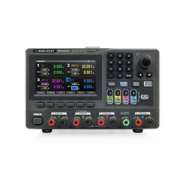
The Siglent SPD4323X is a 4-channel DC Linear Programmable Power Supply equipped with a 4.3-inch TFT-LCD display, friendly human-machine interface, and excellent performance indicators. Real-time waveform display provides engineers with an informative user interface.
SPD4323X offers a total output power of 240 W with a resolution of 1 mV/1 mA. The maximum voltage and current for each channel are as follows:
CH1: 6 V/3.2 A
CH2: 32 V/3.2 A
CH3: 32 V/3.2 A
CH4: 6 V/3.2 A
Kenmerken
Rated output power: 240 W
Rated voltage: 32 V, 12 V, 30 V
Up to four high-precision power supplies with independent controllable outputs, supporting CH2 and CH3 series and parallel connections
Clear graphical interface with waveform and timer display modes
5-digit voltage and current display with minimum resolution of 1 mV, 1 mA
Fast output response time: <50us
The high current channel support remote voltage compensation sense function. The maximum compensation voltage is 0.6 V
Overvoltage protection and overcurrent protection or safe and accurate operation
Equipped with a 4.3-inch TFT-LCD display (480 x 272 resolution)
USB and LAN standard communication
USB-GPIB module is optional
Excellent channel density with up to 4 channels in a 3U half rack package
Internal data storage for setups and parameters
Embedded Web Server with instrument communication that doesn’t require software installation
Fully SCPI programming command set support as well as a LabView driver for remote control and system automation
Specificaties
SPD4323X
SPD4121X
SPD4306X
Channel Output
CH1: Voltage 0 to 6 V Current 0 to 3.2 ACH2: Voltage 0 to 32 V Current 0 to 3.2 ACH3: Voltage 0 to 32 V Current 0 to 3.2 ACH4: Voltage 0 to 6 V Current 0 to 3.2 A
CH1: Voltage 0 to 15 V Current 0 to 1.5 ACH2: Voltage 0 to 12 V Current 0 to 10 ACH3: Voltage 0 to 12 V Current 0 to 10 ACH4: Voltage 0 to 15 V Current 0 to 1.5 A
CH1: Voltage 0 to 15 V Current 0 to 1.5 ACH2: Voltage 0 to 30 V Current 0 to 6 ACH3: Voltage 0 to 30 V Current 0 to 6 ACH4: Voltage 0 to 15 V Current 0 to 1 A
Resolution
1 mV, 1 mA
1 mV, 1 mA
1 mV, 1 mA
Setting Accuracy
Voltage: ±(0.03% of reading+10) mV, Current: ±(0.3% of reading+10) mA
Voltage: ±(0.03% of reading+10) mV, Current: ±(0.3% of reading+10) mA
Voltage: ±(0.03% of reading+10) mV, Current: ±(0.3% of reading+10) mA
Readback Accuracy
Voltage: ±(0.03% of reading+10) mV, Current: ±(0.3% of reading+10) mA
Voltage: ±(0.03% of reading+10) mV, Current: ±(0.3% of reading+10) mA
Voltage: ±(0.03% of reading+10) mV, Current: ±(0.3% of reading+10) mA
Display
4.3" TFT-LCD 5-digit voltage and current display
4.3" TFT-LCD 5-digit voltage and current display
4.3" TFT-LCD 5-digit voltage and current display
Output power
240 W
285 W
400 W
Inbegrepen
1x Siglent SPD4323X Power Supply
1x Power cord (EU)
1x Output test cord (3 A)
1x USB cable
1x Quick start guide
Downloads
Datasheet
Manual
Quick start
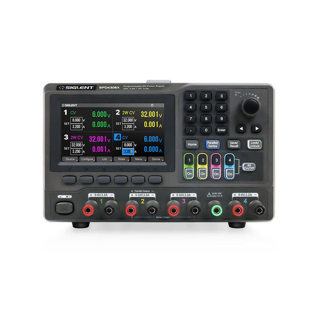
The Siglent SPD4306X is a 4-channel DC Linear Programmable Power Supply equipped with a 4.3-inch TFT-LCD display, friendly human-machine interface, and excellent performance indicators. Real-time waveform display provides engineers with an informative user interface.
SPD4306X offers a total output power of 400 W with a resolution of 1 mV/1 mA. The maximum voltage and current for each channel are as follows:
CH1: 15 V/1.5 A
CH2: 30 V/6 A
CH3: 30 V/6 A
CH4: 15 V/1 A
Kenmerken
Rated output power: 400 W
Rated voltage: 32 V, 12 V, 30 V
Up to four high-precision power supplies with independent controllable outputs, supporting CH2 and CH3 series and parallel connections
Clear graphical interface with waveform and timer display modes
5-digit voltage and current display with minimum resolution of 1 mV, 1 mA
Fast output response time: <50us
The high current channel support remote voltage compensation sense function. The maximum compensation voltage is 0.6 V
Overvoltage protection and overcurrent protection or safe and accurate operation
Equipped with a 4.3-inch TFT-LCD display (480 x 272 resolution)
USB and LAN standard communication
USB-GPIB module is optional
Excellent channel density with up to 4 channels in a 3U half rack package
Internal data storage for setups and parameters
Embedded Web Server with instrument communication that doesn’t require software installation
Fully SCPI programming command set support as well as a LabView driver for remote control and system automation
Specificaties
SPD4323X
SPD4121X
SPD4306X
Channel Output
CH1: Voltage 0 to 6 V Current 0 to 3.2 ACH2: Voltage 0 to 32 V Current 0 to 3.2 ACH3: Voltage 0 to 32 V Current 0 to 3.2 ACH4: Voltage 0 to 6 V Current 0 to 3.2 A
CH1: Voltage 0 to 15 V Current 0 to 1.5 ACH2: Voltage 0 to 12 V Current 0 to 10 ACH3: Voltage 0 to 12 V Current 0 to 10 ACH4: Voltage 0 to 15 V Current 0 to 1.5 A
CH1: Voltage 0 to 15 V Current 0 to 1.5 ACH2: Voltage 0 to 30 V Current 0 to 6 ACH3: Voltage 0 to 30 V Current 0 to 6 ACH4: Voltage 0 to 15 V Current 0 to 1 A
Resolution
1 mV, 1 mA
1 mV, 1 mA
1 mV, 1 mA
Setting Accuracy
Voltage: ±(0.03% of reading+10) mV, Current: ±(0.3% of reading+10) mA
Voltage: ±(0.03% of reading+10) mV, Current: ±(0.3% of reading+10) mA
Voltage: ±(0.03% of reading+10) mV, Current: ±(0.3% of reading+10) mA
Readback Accuracy
Voltage: ±(0.03% of reading+10) mV, Current: ±(0.3% of reading+10) mA
Voltage: ±(0.03% of reading+10) mV, Current: ±(0.3% of reading+10) mA
Voltage: ±(0.03% of reading+10) mV, Current: ±(0.3% of reading+10) mA
Display
4.3" TFT-LCD 5-digit voltage and current display
4.3" TFT-LCD 5-digit voltage and current display
4.3" TFT-LCD 5-digit voltage and current display
Output power
240 W
285 W
400 W
Inbegrepen
1x Siglent SPD4306X Power Supply
1x Power cord (EU)
1x Output test cord (3 A)
1x USB cable
1x Quick start guide
Downloads
Datasheet
Manual
Quick start
Entwicklung intelligenter Sensorknoten, Diagnoseempfänger und LoRa-Zentralen
LoRa ist eine Funktechnik, die weltweit für die Übertragung kleiner Datenmengen über große Entfernungen eingesetzt wird. Ob Sensornetzwerke, industrielle Überwachung, Gebäudeautomation, Landwirtschaft oder andere IoT-Anwendungen – LoRa ermöglicht energiearme Funkverbindungen auch dort, wo große Reichweiten erforderlich sind.
Im Mittelpunkt dieses Buches steht der SX1262, ein moderner LoRa- Transceiver, der zusammen mit dem ESP32-S3 die Grundlage für die entwickelten Sensorknoten bildet. Dabei wird nicht nur die Funktechnik erklärt, sondern vor allem gezeigt, wie der SX1262 praktisch eingesetzt und programmiert wird.
Von der ersten Funkübertragung über die Wahl von Frequenz, Bandbreite, Spreading Factor, Coding Rate und Sendeleistung bis zum vollständigen LoRa-Telegramm entsteht Schritt für Schritt ein funktionsfähiges System. Der ESP32-S3 übernimmt dabei die eigentliche Intelligenz. Er erfasst Sensorsignale, berechnet Messwerte, überwacht Versorgung und Sensor, erkennt Fehler, bestimmt Status und Trend und entscheidet, wann eine Übertragung über LoRa notwendig ist.
Ein besonderer Schwerpunkt liegt auf dem Kommunikationsstandard, dem standardisierten LoRa-Telegramm und der Möglichkeit, neben aufbereiteten Messwerten auch ADC-Rohwerte für die Diagnose zu übertragen. Das Buch führt von den ersten LoRa-Hardware- und Funkversuchen über die Entwicklung intelligenter Sensorknoten bis zum Diagnoseempfänger und zur LoRa-Zentrale. Auch Servicebetrieb und der energiesparende Sleep-Betrieb von ESP32-S3 und SX1262 werden behandelt.
Entwicklung intelligenter Sensorknoten, Diagnoseempfänger und LoRa-Zentralen
LoRa ist eine Funktechnik, die weltweit für die Übertragung kleiner Datenmengen über große Entfernungen eingesetzt wird. Ob Sensornetzwerke, industrielle Überwachung, Gebäudeautomation, Landwirtschaft oder andere IoT-Anwendungen – LoRa ermöglicht energiearme Funkverbindungen auch dort, wo große Reichweiten erforderlich sind.
Im Mittelpunkt dieses Buches steht der SX1262, ein moderner LoRa- Transceiver, der zusammen mit dem ESP32-S3 die Grundlage für die entwickelten Sensorknoten bildet. Dabei wird nicht nur die Funktechnik erklärt, sondern vor allem gezeigt, wie der SX1262 praktisch eingesetzt und programmiert wird.
Von der ersten Funkübertragung über die Wahl von Frequenz, Bandbreite, Spreading Factor, Coding Rate und Sendeleistung bis zum vollständigen LoRa-Telegramm entsteht Schritt für Schritt ein funktionsfähiges System. Der ESP32-S3 übernimmt dabei die eigentliche Intelligenz. Er erfasst Sensorsignale, berechnet Messwerte, überwacht Versorgung und Sensor, erkennt Fehler, bestimmt Status und Trend und entscheidet, wann eine Übertragung über LoRa notwendig ist.
Ein besonderer Schwerpunkt liegt auf dem Kommunikationsstandard, dem standardisierten LoRa-Telegramm und der Möglichkeit, neben aufbereiteten Messwerten auch ADC-Rohwerte für die Diagnose zu übertragen. Das Buch führt von den ersten LoRa-Hardware- und Funkversuchen über die Entwicklung intelligenter Sensorknoten bis zum Diagnoseempfänger und zur LoRa-Zentrale. Auch Servicebetrieb und der energiesparende Sleep-Betrieb von ESP32-S3 und SX1262 werden behandelt.
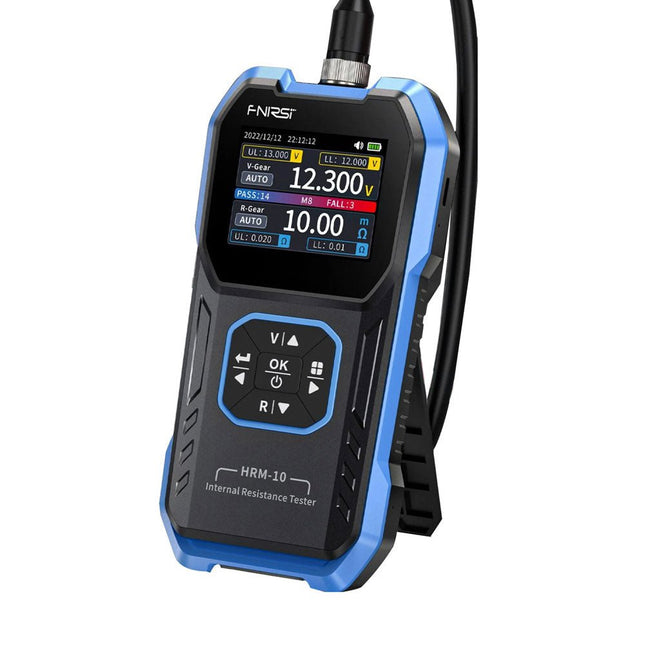
De FNIRSI HRM-10 is een draagbare, zeer nauwkeurige interne weerstands- en spanningstester voor batterijen. Dit apparaat biedt echte vierdraadsmetingen en is ontworpen voor zowel nauwkeurigheid als gebruiksgemak. Het meet automatisch tegelijkertijd de interne weerstands- en spanningswaarden en geeft de resultaten op het HD-kleurenscherm weer. Gebruikers hebben de mogelijkheid om het spannings- en weerstandsbereik handmatig aan te passen aan hun behoeften. Het apparaat bevat ook een sorteermodus die automatisch de goede en slechte batterijen filtert op basis van door de gebruiker ingestelde drempels. Bovendien ondersteunt het de opslag van historische gegevens en is het mogelijk meetgegevens in tabelformaat te exporteren.
Kenmerken
Hoge meetnauwkeurigheid
Tabelgegevens exporteren
Meetresultaten automatisch evalueren
8 drempelinstellingen
HD-kleurenscherm
Opvouwbare standaard
1000 mAh lithiumbatterij
Specificaties
Spanning
Weerstand
Meetbereik
0-100 V (DC)
0-200 Ω
Nauwkeurigheid
±0,5%
±0,5%
Uitrusting
Automatisch, 1 V, 10 V, 100 V
Automatisch, 20 mΩ, 200 mΩ, 2 Ω, 20 Ω, 200 Ω
Instrumenttestsignaalfrequentie
1 Khz (AC)
Oplaadbaar
USB-C (5 V/1 A)
Ingebouwde batterij
1000 mAh lithiumbatterij
Gebruikerskalibratie
Ja
Sorteermodus
Ja
Geschiedenisrecord
Ja
Export van opgenomen gegevens
Ja
Werkomgeving
–10°C tot +45°C, relatieve vochtigheid <80%
Opslagomgeving
–20°C tot +80°C, relatieve vochtigheid <80%
Afmetingen
158,7 x 80,5 x 28,4 mm
Gewicht
225 g
Inbegrepen
1x FNIRSI HRM-10 interne weerstandstester
1x Clip-testlijn
1x USB-C datakabel
1x Manual
Downloads
Manual
Firmware V0.3