
Zoekresultaten voor "raspberry OR pi OR high OR quality OR camera OR module"
-

Elektor Digital Elektor Juillet/Août 2025 (PDF) FR
Le téléchargement intégral de ce numéro est disponible pour nos membres GOLD et GREEN sur le site Elektor Magazine ! Pas encore membre ? Cliquez ici. tableau de bord OBD2Des cadrans anciens aux données en temps réel OBD2 : ajoutez un compte-tours et un indicateur de changement de vitesse à votre voitureRétro, mais extrêmement utile capteurs de vision et LiDAR pour la robotique Sensor+Test 2025 et PCIM 2025 mesures sans contact du champ électrique (1)Membrane vibrante pour mesurer des tensions continues ou des champs électriques statiques détecteur de courrier sans filCapteurs optiques, radars… quelques options à explorer Elektor Mini-WheelieUn robot auto-équilibré cellules solairesDrôles de composants, la série premiers pas avec un capteur radar moderneUn capteur précis qui ne passe pas inaperçu sur le vifUsine de papier CybersécuritéDes temps difficiles pour les hackers Infographie : IdO et capteurs le Bluetooth 6.0 pour des applications de télémétrie amélioréesCette nouvelle version offre des fonctions de localisation améliorées découvrez la communication sans fil avec BeagleY-AI Projet 2.0Corrections, mises à jour et courrier des lecteurs démarrer en électronique……Conclusion sur les ampli-op un puissant assistant de codage de l'IAAccélérez votre développement avec Continue et Visual Studio Code contrôleur de charge solaire avec MPPT (2)Le circuit détecteur d'obstacles à ultrasonsUn projet simple pour aider les malvoyants une odyssée de l'IABilan du premier semestre synthétiseur MIDI autonome Raspberry Pi (3)plus intelligent avec une interface utilisateur Meshtastic : un projet de démoUn réseau intelligent de noeuds LoRa générateur analogique de fréquences audioGénérateur de signaux sinusoïdaux de haute qualité à fréquence réglable
€ 10,95
-

Elektor Digital H0W2: Get Started with the SensorTile.box (E-book)
STmicroelectronics’ wireless IoT & wearable sensor development kit ‘SensorTile.box’ is a portable multi-sensor circuit board housed in a plastic box and developed by STMicroelectronics. It is equipped with a high-performance 32-bit ARM Cortex-M4 processor with DSP and FPU, and various sensor modules, such as accelerometer, gyroscope, temperature sensor, humidity sensor, atmospheric pressure sensor, microphone, and so on. SensorTile.box is ready to use with wireless IoT and Bluetooth connectivity that can easily be used with an iOS or Android compatible smartphone, regardless of the level of expertise of the users. SensorTile.box is shipped with a long-life battery and all the user has to do is connect the battery to the circuit to start using the box. The SensorTile.box can be operated in three modes: Basic mode, Expert mode, and Pro mode. Basic mode is the easiest way of using the box since it is pre-loaded with demo apps and all the user has to do is choose the required apps and display or plot the measured data on a smartphone using an app called STE BLE Sensor. In Expert mode users can develop simple apps using a graphical wizard provided with the STE BLE Sensor. Pro mode is the most complex mode allowing users to develop programs and upload them to the SensorTile.box. This book is an introduction to the SensorTile.box and includes the following: Brief specifications of the SensorTile.box; description of how to install the STE BLE Sensor app on an iOS or Android compatible smartphone required to communicate with the box. Operation of the SensorTile.box in Basic mode is described in detail by going through all of the pre-loaded demo apps, explaining how to run these apps through a smartphone. An introduction to the Expert mode with many example apps developed and explained in detail enabling users to develop their own apps in this mode. Again, the STE BLE Sensor app is used on the smartphone to communicate with the SensorTile.box and to run the developed apps. The book then describes in detail how to upload the sensor data to the cloud. This is an important topic since it allows the sensor measurements to be accessed from anywhere with an Internet connection, at any time. Finally, Pro mode is described in detail where more experienced people can use the SensorTile.box to develop, debug, and test their own apps using the STM32 open development environment (STM32 ODE). The Chapter explains how to upload the developed firmware to the SensorTile.box using several methods. Additionally, the installation and use of the Unicleo-GUI package is described with reference to the SensorTile.box. This PC software package enables all of the SensorTile.box sensor measurements to be displayed or plotted in real time on the PC.
€ 29,95
Leden: € 26,96
-

SEQURE SEQURE T55 Smart Mini Soldeer Hot Plate (55x55 mm)
De SEQURE T55 Smart Mini Temperatuur Verstelbare Soldeerplaat is een compact en efficiënt apparaat, ontworpen voor nauwkeurig voorverwarmen en desolderen. Met zijn instelbare temperatuurbereik van 50°C tot 280°C is hij geschikt voor diverse toepassingen, zoals het repareren van mobiele telefoons, het monteren van printplaten, enz. Kenmerken Instelbaar verwarmingstemperatuurbereik: 50°C tot 280°C Uitgerust met een hittebestendige keramische temperatuursensor, voor een zeer nauwkeurige gegevensmeting bij continu hoge temperaturen. Stopt automatisch met verwarmen na het bereiken van de vooraf ingestelde werktijd. Ondersteunt PD, QC en DC (max. 25 V) Intelligent temperatuurregelalgoritme voor temperatuurcompensatie en vermogensaanpassing. OLED-display met een resolutie van 128 x 32 en een ingebouwde zoemer om de bedrijfsstatus aan te geven. °C/°F-conversie Specificaties Verwarmingsoppervlak 55 x 55 mm Werktemperatuur 50-280°C Max. spanning 25 V Max. vermogen 95 W Aanbevolen spanning 19-25 V PD-voeding PD 20 V ≥3 A Voedingsmodi PD, QC, DC Interface USB-C Display 128 x 32 OLED Menutalen Engels, Russisch en Chinees Afmetingen 55 x 60 x 37 mm Gewicht 92 g Inbegrepen 1x SEQURE T55 Smart Mini Soldeerplaat 1x PD 65 W Voeding (EU) 1x Snellaadkabel (100 W/5 A)
€ 49,95
Leden: € 44,96
-

Elektor Digital Elektor March/April 2023 (PDF)
Elektor GREEN and GOLD members can download their digital edition here. Not a member yet? Click here. Cloc 2.0The Alarm Clock You've Always Wanted RP2040 PIO in PracticeExperiments Using the RP2040’s Programmable I/O Poor Man's ChipTweakerWe Have (Low-Budget) Ways of Making You Talk USB True Random Number GeneratorTwo PICs for the Price of One AVR Pimp My MicSelf-Designed Level Booster FFT with a MaixduinoFrequency spectrum display From Life’s ExperienceDesign Logic (or Non-Logic) UCN5804 Stepper Motor DriverPeculiar Parts, the Series Circuit Simulation With Micro-CapFirst Steps in a Complicated World PAUL Award 2022Young Technical Talents and Their Creative Solutions My First Software-Defined RadioBuilt in Less Than 15 Minutes Microcontroller Documentation Explained (Part 1)Datasheet structure What’s Next for AI and Embedded Systems?Tools, Platforms, and Writer Replacements Digitizing Vertical Farming Infographics: Embedded and AI Today and Tomorrow An Introduction to TinyML JetCarrier96A Versatile NVIDIA Jetson Development System Case Study: Taking EV Charging Global with a Universal RFID Solution High-Performance in Every ClassComputer-on-Module Standards Starting Out in ElectronicsLet’s Get Active! I²C Communication Using Node.js and a Raspberry PiSee Your Sensor Data in a Browser Video Output with Microcontrollers (2)VGA and DVI Output The Metronom Real-Time Operating SystemAn RTOS for AVR Processors DVI on the RP2040An Interview with Luke Wren, Chip Developer at Raspberry Pi Display HAT MiniShow the Weather Forecast on Raspberry Pi! WEEF 2022 Awards: Celebrate the Good Hexadoku
€ 7,50
-

Elektor Digital Elektor Novembre/Décembre 2021 (PDF)
TRAITEMENT D'IMAGES AVEC LE KIT JETSON NANO DE NVIDIA2e partie : reconnaissance d'imagesELEKTOR JUMPSTARTER – DU NOUVEAUCampagnes à venirTRACEUR GPS À CODE SOURCE OUVERTTraccar cartographie les déplacements de véhicules, sans recours à un serveur tiers du nuageTESTEUR MULTIFONCTION LCR-T7 DE JOY-ITTest de semi-conducteurs passifs, discrets et de télécommandes IRSYNTHÉTISEUR DE BRUITDu bruit à la musique avec le PRBSynth1DÉMARRER EN ÉLECTRONIQUE…Easier than Imagined! ... Continuing with the CoilVOYAGE DANS LES RÉSEAUX NEURONAUX (2E PARTIE)Les neurones logiquesPROBLÈMES DE SÉCURITÉ ? COMBATTEZ LE FEU PAR LE FEU !Extension à mémoire analogique, protégée par ampoule de flash, pour la boîte à témoin d'effractionKIT DU LCR-MÈTRE 2 MHZ D'ELEKTORBALISES BLUETOOTH : LA PRATIQUEGéolocalisation intra murosC PROGRAMMING ON RASPBERRY PIExtrait : communiquer par Wi-FiTEST DE PRÉCONFORMITÉ CEM POUR UN PROJET ALIMENTÉ EN COURANT CONTINUPartie 2 : le matériel et son utilisationPROPELLER 2 DE PARALLAX (5)La fonction de « broche intelligente »MODBUS SANS FIL (PARTIE 1)Matériel et programmationJUNIOR COMPUTEREn forme après 40 ans de sommeilCONSTRUIRE SON PROPRE ÉTALONNEUR DE HAUTE PRÉCISION−10 V à +10 V, 0 à 40 mA, 0,001 %ARDUINO NANO RP2040 CONNECT EN DÉTAILRaspberry Pi RP2040 + Wi-Fi + BluetoothLE CORPS PHYSIQUE DE L'INTELLIGENCE ARTIFICIELLEPROJET 2.0corrections, mises à jour et courriers des lecteursCRÉATION D'INTERFACES GRAPHIQUES EN PYTHON AVEC GUIZEROInstallez la bibliothèque Python guizero et créez vos propres interfaces graphiques.KIT DE MESURE DU CO2 POUR SALLE DE CLASSEMontage à base d'ESP8266, conçu par l'Université des Sciences Appliquées d'Aix-la-ChapelleMK484, RADIORÉTRO PO/GO...Toujours le plaisir de construire !60 ANS D'ELEKTORQue la lumière soit !HEXADOKUThe Original Elektorized Sudoku
€ 10,95
-

Seeed Studio Seeed Studio RF Explorer 3G Combo Spectrumanalyzer
The Seeed Studio RF Explorer 3G Combo is a handheld digital spectrum analyzer and an affordable tool for working across a wide range of popular frequency bands. It is based on a highly integrated frequency synthesizer and a double-balanced mixer, providing high performance, compact dimensions, low power consumption, and excellent value. Designed for both indoor and outdoor use, the RF Explorer 3G Combo can also be connected to a PC via a standard Mini-USB 2.0 connector for additional functionality. This model combines a WSUB1G base unit with an RFEMWSUB3G expansion module, supplied fully assembled and tested. It features two SMA connectors and includes two antennas: a dual-band 144/430 MHz telescopic antenna for sub-GHz frequencies and a helical whip antenna for the 2.4 GHz band. Additional frequency-specific antennas may be required for optimal performance in certain supported frequency ranges. This combination provides the wide frequency coverage of the WSUB3G module together with the high sensitivity and fast response of the WSUB1G unit in the commonly used sub-1 GHz frequency range. Kenmerken Pocket size and light weight Solid aluminum metal case Includes a transport EVA carry case for RF Explorer Spectrum Analyzer mode with Peak Max and Hold, Normal, Overwrite and Averaging modes Lifetime free firmware upgrades available, open to community requested features High capacity Lipo for 16+ hours of continuous run, rechargeable by USB Windows PC client Open Source Can be extended with internal Expansion Modules for additional band and functionality Wide band coverage to all popular RF frequencies, starting at 15 MHz and going up to 2.7 GHz. This includes very interesting frequency areas such as 2 m HAM radio, all VHF and UHF, FM radio, GPS, WiFi and WiMax, Bluetooth, etc. Firmware: RF Explorer 3G Combo is delivered with upgraded firmware v1.09. Note some of the features and operation accuracy will be improved in upcoming free firmware revisions. Specificaties Battery Lithium Cells / Batteries contained in equipment UN3481 - PI967 Frequency band 15-2700 MHz Frequency span 112 KHz - 600 MHz Graphics LCD 128 x 64 pixels, great visibility outdoors PC Windows client Supports Windows (32 and 64 bits) Backlight For great indoor visibility 2 standard SMA 50 ohms connector, One for Sub-GHz wideband Nagoya NA-773 telescopic antenna included and another 2.4 GHz one for 15-2700 MHz band with helical antenna included. Amplitude resolution 0.5 dBm Dynamic range Left SMA port (WSUB1G) -115 dBm to 0 dBm Right SMA port (WSUB3G) -110 dBm to -10 dBm Absolute Max input power Left SMA port (WSUB1G) +5 dBm Right SMA port (WSUB3G) +30 dBm Average noise level (typical) -110 dBm Frequency stability and accuracy (typical) ±10 ppm Amplitude stability and accuracy (typical) ±6 dBm Frequency resolution 1 KHz Resolution bandwidth (RBW) Automatic 3 KHz to 600 KHz Weight 185 g Dimensions 113 x 70 x 25 mm Inbegrepen Seeed Studio RF Explorer 3G Combo Spectrum Analyzer Nagoya NA-773 wideband telescopic antenna 2.4 GHz band antenna EVA Case Documentatie For more info and to get started with your RF Explorer, visit the start page. For questions and support, please visit https://support.rf-explorer.com
€ 279,95
-

Elektor Digital Elektor November/December 2026 (PDF) EN
Elektor GREEN and GOLD members can download their digital edition here. Not a member yet? Click here. AI Tools for Hardware PrototypingWhat Helps, What Does Not, and Where the Engineer Still Has to Sit ZSWatch — From Idea to ProductPart 1: A Completely Open Smartwatch Three-Way Tone ControlHigh-End — For That Little Bit Extra electronica Fast Forward 202610 Years of Innovation Microcontroller PrototypingAn Overview of Popular Boards Prototyping BreadboardsPeculiar Parts, the Series Designing for OrbitA Maker’s Guide to COTS Selection, Radiation Resilience, and Mission Architecture Thermal Management for Reliable ElectronicsWhen Every Degree Counts From Concept to GadgetBuilding Embedded Systems That Ship Understanding the EU Cyber Resilience ActWhat the CRA Demands and How to Meet It: A Guide for Embedded Engineers Lusight: Printed Displays You Can Reveal with Your PhoneDiscover What Is Inside the Badge on the Cover of Elektor’s electronica Edition Teaching a Robot Arm to See and MoveAI-Driven Manipulation Using a 3D-Printed Robot Loop Antenna with RF BricksPart 2: Signal Processing From Prototype to ProductionPractical Lessons from the Elektor Community Project UpdatesFeedback, Ideas, Corrections Handheld Audio GeneratorA Reference Signal Source for Quick Audio Systems Setup AudiotronicsMore Distortion, and a Level-Matching Amplifier 2026: An AI OdysseyWhen AI Starts Building AI Wireless Workshop (2)Radio Modules Unlocked: 2.4-GHz nRF24L01P Transceiver The Digital Path Building an Open-Source SmartwatchDaniel Kampert on ZSWatch, Open Hardware, and Engineering Trade-Offs How to Prepare for Professional SMD Assembly Engineering Beyond the BenchSystem Integration, Troubleshooting, and Real-World Testing Elektor at 65Projects from Novembers and Decembers Past Avionics Instrument SimulatorESP32-S3-Based, with Round HMI Display
€ 9,50
-

Elektor Digital Elektor Circuit Special 2026 (PDF) NL
Elektor GREEN en GOLD leden kunnen deze uitgave hier downloaden. Nog geen lid? Klik hier om een lidmaatschap af te sluiten. Een stroombron voor het testen van Z-diodesControle van Z-diodes van 1 tot 54 V bij 1 tot 50 mA ESD polsbandtesterEen testapparaat met indicatie voor ‘goed’, ‘grensgeval’ en ‘afgekeurd’ Testapparaat voor de respons op piekbelastingen van voedingenEen generator voor repeterende stapsgewijze belasting voor laboratoriumvoedingen Euclidische sequencer zonder microcontrollerTriggerpatronen en CV-sequenties met eenvoudige CMOS-logica LED-knipperlicht voor heksystemen en meer, inclusief geluidssignaal Printen nodig? De Elektor PCB-service staat voor u klaar Tandenborstel-timerMet een kleine PIC Een contactloos magnetisch combinatieslotMet de AS5600 rotatie-positie sensor Batterijgevoede ruisarme voorversterkervoor dynamische microfoons Het Arduino Nano testLabMeten, sturen en regelen Rhythmische basverlichtingBenadruk het ritme van je muziek Low-cut filterGeen risico op audio-terugkoppeling op uw systeem Nauwkeurige 1 Hz blokgolfgenerator voor breadboardsEen betrouwbare klokpuls op basis van CMOS 555 onderstebovenDutycycles tot nul Van Halfgeleidergids tot Circuit Specials65 jaar innovatie op het gebied van elektronica Elektrische isolatieCAN-interface met digitale isolator en voedingsmodule SpongillatorEen sponsgebaseerde oscillator Echte willekeurige getallengeneratorMet geïntegreerde chi-kwadraattoets 3D-viewer voor HTML-pagina'sEenvoudig en vrijwel zonder code Programmeren met TLScriptEen scripttaal voor metingen, tests en besturing Schakelingsontwerp: tips van experts FeedbackWat is het en waarom is het belangrijk? Eén board, eindeloze ideeën: Arduino UNO QVan retro-gaming tot realtime milieumonitoring Hoe u een donut-antenne repareert Standby-KillerEen echte aan/uit-schakelaar voor uw tv Batterijen testenBatterijen meten met de Arduino Nano Voeding voor audioversterkersEen goede voeding zonder netbrom HF prototype printplatenMaak zelf snel een prototype printplaat Type 3-overspanningsbeveiligingEen type 3-overspanningsbeveiliging voor uw gevoelige apparatuur IoT-kamerthermostaat boardMet een op ESP32-C3/S3 gebaseerde Xiao MCU-module Van star naar slimFlexibele en gedrukte elektronica, tussen visie en industriële realiteit
€ 9,95
-
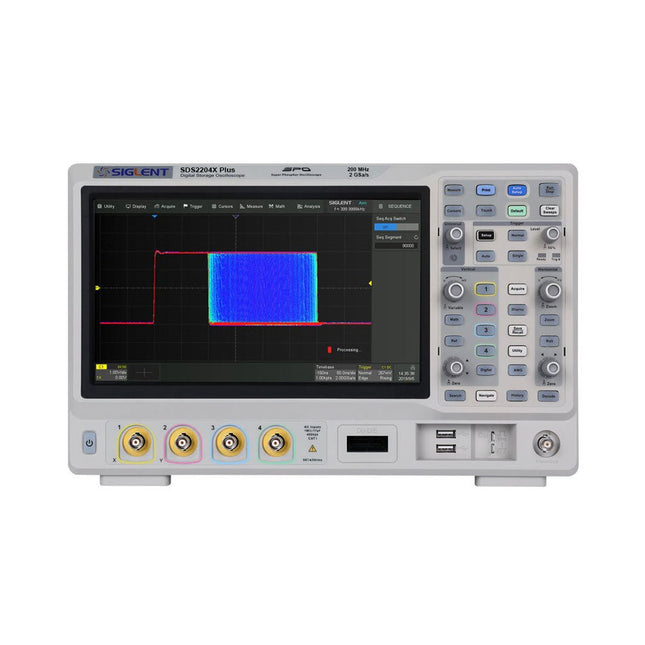
Siglent Siglent SDS2204X Plus 4-ch Oscilloscope (200 Mhz)
Siglent's SDS2000X Plus series Digital Storage Oscilloscopes are available in bandwidths of 100 MHz, 200 MHz, and 350 MHz, have a maximum sample rate of 2 GSa/s, a maximum record length of 200 Mpts/ch, and up to 4 analog channels + 16 digital channels mixed-signal analysis ability. The SDS2000X Plus series employs Siglent’s SPO technology with a maximum waveform capture rate of up to 120,000 wfm/s (normal mode, up to 500,000 wfm/s in Sequence mode), 256-level intensity grading display function plus a color temperature display mode. It also employs an innovative digital trigger system with high sensitivity and low jitter. The trigger system supports multiple powerful triggering modes including serial bus triggering. History waveform recording, Sequence acquisition, Search and Navigate functions allow for extended waveform records to be captured, stored, and analyzed. An impressive array of measurement and math capabilities, options for a 50 MHz waveform generator, as well as serial decoding, mask test, bode plot, and power analysis are also features of the SDS2000X Plus. A 10-bit acquisition mode helps to satisfy applications that require more than 8-bit resolution. The large 10.1’’ capacitive touch screen supports multi-touch gestures, while the remote web control, mouse and external keyboard support greatly improve the operating efficiency of the SDS2000X Plus. Features 100 MHz, 200 MHz, 350 MHz (upgradable to 500 MHz) models Real-time sampling rate up to 2 GSa/s Record length up to 200 Mpts Serial bus triggering and decoder, supports I²C, SPI, UART, CAN, LIN, CAN FD, FlexRay, I²S and MIL-STD-1553B Provide 10 bit mode, Vertical and Horizontal Zoom Capacitive touch screen supports multi-touch gestures Siglent SDS2000X Plus Oscilloscopes SDS2102X Plus SDS2104X Plus SDS2204X Plus SDS2354X Plus Bandwidth 100 MHz 100 MHz 200 MHz 350 MHz Channels 2 4 4 4 Real-time sampling rate 2 GSa/s 2 GSa/s 2 GSa/s 2 GSa/s Capture rate 120,000 wfm/s 120,000 wfm/s 120,000 wfm/s 120,000 wfm/s Memory depth 200 Mpts/ch 200 Mpts/ch 200 Mpts/ch 200 Mpts/ch Included Siglent SDS2204X Plus Oscilloscope Passive probes Power cord USB cable Manual Downloads Datasheet Manual Quick guide User manual Firmware
€ 1.838,23
-

Elektor Digital Practical Electronics Crash Course (E-book)
Learning circuit design the fun way Welcome to the world of electronics! Getting started in electronics is not as difficult as you may think. Using this book, you will explore and learn the most important electrical and electronics engineering concepts in a fun way by doing various experiments and by simulating circuits. It will teach you electronics practically without getting into complex technical jargon and long calculations. As a result, you will be creating your own projects soon. No prior knowledge of electronics is required, only some basic algebra is used in a few simple calculations. Many tested and working projects and simulations are presented to familiarise yourself with the construction of electronic circuits. Circuit simulation is introduced at an early stage to enable you to experiment with circuits easily without breaking anything. You will learn: The concepts of voltage, current, and power AC and DC Basic lamp circuits with switches Passive components: resistors, capacitors & inductors RC & RCL circuits Electromagnetism Loudspeakers, relays, buzzers, and transformers Active components: diodes & LEDs, bipolar transistors & MOSFETs Transistor-based switching circuits Optocoupler circuits Astable & monostable multivibrators Using the 555 timer IC The operational amplifier Digital logic Advanced examples: amplifiers, oscillators, filters, and sensors Test and measurement tools Microcontrollers: Arduino UNO, ESP32, Raspberry Pi Pico, and Raspberry Pi Reading datasheets and best practices for selecting components EMC & EMI and norms & regulations
€ 32,95
Leden: € 29,66
-

Miniware Miniware MDP-P906 Digital Power Supply (300 W)
De MDP-P906 heeft een ingebouwde ventilator en een maximaal uitgangsvermogen van 300 W, wat toereikend is voor een breed scala aan testbehoeften en toepassingen. Via 2,4 GHz draadloze communicatie kan hij worden aangesloten op de MDP-M01 Smart Digital Monitor module om daarmee een flexibele combinatie van meerdere kanalen van 300 W per kanaal te kunnen realiseren. De MDP-P906 heeft een basis, stabiliteit en betrouwbaarheid die te vergelijken is met een professionele voeding. Hij kan puur stroom leveren én krachtige functies hieraan toevoegen, zoals programmeerbare uitgang, getimede uitgang, getimede regeling, automatische compensatie, boost modus, enz. Dit maakt hem tot een kosteneffectieve, slimme en op maat programmeerbare lineaire DC-voeding. De MDP-P906 heeft een zorgvuldig CNC-gefreesde aluminium behuizing, met verfijnde afwerking, eigentijds, bescheiden en prachtig uiterlijk. Hij wijkt hiermee volledig af van het standaard uiterlijk van een traditionele desktop voeding. Door een stackable modulair ontwerp en de draadloze communicatie kan de MDP-P906 onafhankelijk of onderling gekoppeld worden gebruikt, zowel in de normale werkruimte als bij onderhoud op locatie. De MDP-P906 is een perfecte oplossing voor elektrotechnici, met name servicemonteurs, om bij verschillende situaties en toepassingen de stroom te leveren. Ingebouwde stille ventilator, instant cooling, voor een stabiele en efficiënte output! Slimme lineaire compensatie, constante spanning & constante stroom Positieve en negatieve output, series boost, parallelle stroomverdeling Toepassingen Universele tests en onderwijsexperimenten in R&D laboratoria Onderhoud van digitale producten Eigendomsverificatie en foutdiagnose van apparaten en circuits Noodstroomvoorziening voor modelvliegtuigen en voertuigen Voedingen testen van RF en microgolfcircuits of -modules Kwaliteitscontrole en kwaliteitsinspectie Zuivere voeding voor zeer nauwkeurige digitaal-analoge hybride circuits en Hi-Fi audioapparaten Specificaties Input DC 4.2-30 V / 14 A (Max)QC 3.0/PD2.0, 20 V / 5 A (Max) Uitgang 0-30 V / 0-10 A, 300 W (Max) Conversie efficiëntie 95% Output resolutie 10 mV / 2 mA, tot 1 mV / 1 mA via Display Control module Output nauwkeurigheid 0,03%+5 mV0,05%+2 mV Adjustment rate Load adjustment rate <±0,01%Power adjustment rate <±0,01% Ripple en noise <250 uVrms, 3 mVpp; 2 mArms Transient response <4 uS Beveiligingen Te hoge voedingsspanning, onderspanning, omgekeerd aansluiten, te hoge uitgangsstroom, retourstroom en oververhitting Overig Automatisch afsluiten en naar micro-power modeOndersteuning van USB firmware upgrade Afmetingen 112 x 66 x 20 mm Gewicht 181 g Inbegrepen 1x MDP-P906 digitale voeding 2x uitgangskabel 1x gebruikershandleiding Downloads User Manual v1.1 Firmware v1.32
€ 171,95
-

Elektor Labs Elektor Low-noise Labvoeding
De low-noise labvoeding van Elektor is een volledig analoge, instelbare, symmetrische unit met gemiddeld vermogen, zonder schakelende of digitale componenten. De uitgangsspanning is instelbaar tussen 0 V en ±22 V, en de uitgangsstroom kan worden ingesteld van 0 A tot 1 A. Doordat elke vorm van schakeltechniek wordt vermeden, levert het ontwerp extreem weinig ruis. Voor de weergave van beide uitgangsspanningen en -stromen worden vier kleine analoge paneelmeters met draaispoel gebruikt. De meeste moderne laboratoriumvoedingen en AC-adapters maken gebruik van schakelende technieken. Zelfs de beste uitvoeringen vertonen onvermijdelijk hoogfrequente rimpel en andere schakelartefacten op hun uitgang, die het testen van gevoelige analoge schakelingen kunnen verstoren en metingen van kleine signalen kunnen beïnvloeden. Om dit te voorkomen, is het concept hier een volledig analoge voeding. Hoewel deze minder efficiënt is dan vergelijkbare schakelende voedingen, is de lagere efficiëntie bij gebruik op de testbank nauwelijks van belang en zorgt deze voor schonere en betrouwbaardere meetresultaten. Omdat veel analoge schakelingen een symmetrische voeding vereisen, levert dit ontwerp positieve en negatieve uitgangsspanningen van gelijke grootte. Een kleine hoeveelheid afregeling is beschikbaar om eventuele onbalans te compenseren. Uiteraard is ook een instelbare stroombegrenzing aanwezig. De kit bevat de onderdelen die nodig zijn om de voeding te bouwen, met uitzondering van de transformatoren. Specificaties Uitgangsspanning 0…+22 V, 0, −22 V Uitgangsstroom 0…+1 A, 0…−1 A Ruis −85 dBV (bij 0,95 A/20 V, B = 22 kHz) −84 dBV (bij 0,95 A/20 V, B > 500 kHz) Rimpelspanning 50 µVRMS (bij 950 mA/20 V, B = 22 kHz, voornamelijk 100-Hz-component) Inbegrepen 3x printplaten: regelaar (PCB-1), netfilter (PCB-2) en transformator (PCB-3) Alle componenten, behalve de AC-transformatoren 4x draaispoelmeters Extra onderdelen voor de bedrading (draden, banaanstekkerbussen, IEC-voedingsmodule, enz.) Niet inbegrepen De drie AC-transformatoren Een behuizing Onderdelenlijst Voor de regelaar-printplaat (240386-1) Weerstanden (250 mW, 1%) R1 = 12 Ω R2, R8, R37, R62 = 1 MΩ R3, R7, R10, R13, R17, R20, R22, R30, R35, R42, R45, R47, R55, R60 = 100 Ω, 600 mW R4, R5 = 4.7 kΩ R6 = 100 kΩ R9, R12, R14, R36, R38, R39, R61, R63, R66, R72, R78, R79 = 10.0 kΩ, 600 mW R11 = 9.76 kΩ, 600 mW R15, R40 = 44.2 kΩ, 600 mW R16, R41, R77 = 1 kΩ R18, R43 = 1.5 kΩ, 1 W, 5% R19, R44 = 470 Ω, 1 W, 5% R21, R46 = 330 Ω, 600 mW R23, R24, R48, R49 = 1.0 Ω, 1 W R25, R50 = 1 kΩ, 1 W, 5% R26, R28, R51, R53 = 1.000 kΩ 0.1%, 15 ppm/C R27, R29, R52, R54 = 10.00 kΩ 0.1%, 15 ppm/C R31, R56 = 1.2 kΩ, 1 W, 5% R32, R57 = 47 kΩ R33, R58 = 270 Ω R34, R59 = 27 kΩ R64, R69 = 12.0 kΩ R65 = 3.0 kΩ, 600 mW R67, R80 = 470 Ω, 600 mW R68, R70 = 6.8 kΩ, 600 mW R71 = 30.0 kΩ,, 600 mW R73, R74, R75, R76 = 10 MΩ P1, P2, P3 = 10 kΩ, 200 mW, 20%, potentiometer, 1 turns, single, lin., panel mount P4, P5 = 500 Ω, 500 mW, 10%, trimmer, 25 turns, 3296Y-1-501LF Bourns P6, P7 = 10 kΩ, 500 mW, 10%, trimmer, 25 turns, 3296Y-1-501LF Bourns Condensatoren C1 = 100 nF, 50 V, 10%, ceramic X7R, LS 5 mm C2, C3, C6, C7, C30 = 10 µF, 63V, 20%, LS 2.5 mm, 3000hours@105°C C4, C5, C8, C9, C13, C14, C18, C19, C23, C24, C28, C29, C31, C32, C38, C39 = 100 nF, 250 V, 10%, PET, LS 7.5 mm C10, C20 = 47 nF, 100 V, 5%, PET, LS 5 mm C11, C21 = 10 nF, 100 V, 5%, PET, LS 5 mm C12, C22 = 220 µF, 35 V, 20%, 0.024 Ω, LS2.5/3.5 mm, Ir 3.4 A, 2000hours@125°C, polymer C15, C25 = 120 µF, 50 V, 20%, ESR 0.02 Ω, Diam. 10 mm max., LS 5 mm C16, C26 = 15 nF, 100 V, 5%, PET, LS 5 mm C17, C27 = 47 nF, 100 V, 5%, PET, LS 5 mm C33, C34 = 22 µF, 50 V, 20%, LS 2 mm, 10000 hours @ 105°C C35, C36, C44, C45 = 1 µF, 100 V, 10%, LS 5 mm, ceramic X7R C37 = 100 uF, 50 V, 20%. LS 3.5 mm C40, C41, C42, C43, C46, C47, C48, C49 = 1000 µF, 50 V, 20%, LS 5/7.5 mm, Ir 3.32 A, 10000hours@105°C, D 16 mm C50, C51, C52, C53 = 47 nF, 100 V, 10%, ceramic X7R, LS 5 mm Spoelen L1, L2 = 4.7 µH, 3.2 A, 0.033 Ω, LS 5 mm, RLB0914-4R7ML Bourns L3 = Commom mode choke, 14.5 mH, 3 A, SSRH24NH-30145 Kemet Halfgeleiders D1, D2, D3, D4, D5, D9, D10, D11, D15 = BAT85, DO-34 D6, D7, D12, D13 = SR560, DO-201AD D8, D14, D16 = 1N4148, DO-35 D17 = Zenerdiode, 5.6 V, 0.5 W, DO-41 D18, D19 = 1N4004, DO-41 D20, D21 D22, D23 = V30100CI-M3/P, dual common cathode, TO-220 D24 = Zener diode, 30 V, 1 W, DO-41 LED1, LED2 = LED, red, T-1 (3 mm) LED3, LED4 = LED, green, T-1 (3 mm) TVS1, TVS2 = BZW50-33B, R6 T1, T2, T4 = BC337.25, TO-92 T3 = NJW0302G, TO-3P T5, T6, T8 = BC327.25, TO-92 T7 = NJW0281G, TO-3P T9 = BD139, TO-126 (SOT-32) IC1 = LM334Z, TO-92 IC2 = LM4040AIZ-5.0/NOPB, TO-92 (TO-226AA-3) IC3, IC4 = OPA2992IDR, SOIC-8 IC5, IC6 = OPA4992IDR, SOIC-14 IC7 = OPA992IDBVR, SOT-23-5 IC8 = LM339N, DIP-14 IC9 = LM317, TO-220 IC10 = LM337, TO-220 Overige F1, F2 = 5×20 mm fuse, 1.6 A, fast acting HS1, HS2 = Heatsink MC33271 (for T3/T7), 2.7°C/W, PCB mount, height 63.5 mm K1, K4 = 3-way screw terminal block, LS 3.5 mm, max. 1.5 mm² K2, K3 = 3-way screw terminal block, LS 3.5 mm, max. 1 mm² M1, M3 = Moving coil meter, Range 30 V, type 91C4, 45×45 mm M2, M4 = Moving coil meter, Range 1 A, type 91C4, 45×45 mm² RE1 = Relay DPDT,5V, UA2-5NU Diversen 3× 3-way screw terminal block, LS 3.5 mm, max. 1 mm² (for P1, P2, P3) 4× Pin header, 1×2, vertical, pitch 2.54 mm (for LED1, LED2, LED3, LED4) 4× Pin socket, 1×2, vertical. pitch 2.54 mm (for LED1, LED2, LED3, LED4) 2× Heatsink FK222SA220, 20°C/W, PCB mount (for IC9 & IC10) 2× Mica thermal pad for TO-220, 12×18×0.05 mm (for IC9 & IC10) 2× Insulating bushing IB 6, TO-220 (for IC9 & IC10) 2× Ceramic thermal pad, 23×20×2 mm (for T3 & T7) 2× PCB Fuse Holder, for 5×20 mm fuse, 10 A (for F1, F2) 2× Cover for PCB Fuse Holder, transparent (for F1, F2) 2× 2-way screw terminal block, LS 3.5 mm, max. 1 mm² (for M1 & M3) 2× 2-way screw terminal block, LS 3.5 mm, max. 1.5 mm² (for M2 & M4) 8× M3 solder lug, thickness 0.35 mm (for M1…M4) M4 solder lug, thickness 0.35 mm (to connect 4 mm banana connectors) Screened cable, 1 pair, 2×24 AWG/0.22 mm², 1 m (for P1, P2 & P3) IC socket, DIP, 14 contacts (for IC8) M3 washer, plain, steel M3 screw, 16 mm, steel, pan head M3 nut M3 spring washer 50 mm M3 standoff, steel, male-female 12 mm M3 standoff, steel, male-female 10 mm M3 standoff, steel, male-female M3 screw, 8 mm, steel, pan head Voor de netfilter-printplaat (240386-2) Weerstand R1 = 220 kΩ, 1 W, 500 V, 5% Condensatoren C1, C2 = 470 nF, 305 VAC, Class X2, 11 × 27 mm max., LS 15/22.5 mm C3, C4, C5, C6 = 2.2 nF, 300 VAC, Class Y2, 13 × 4 mm, LS 10 mm, PP Spoelen L1, L2 = Common-mode choke, 6.8 mH, 1.7 A, TDK B82732R2172B030 Halfgeleider MOV1 = TVS varistor, 300 VAC, S14K300 (230 VAC, B72214S0301K101) and SK14K150 (150 VAC, B72214S0151K101) Overige K1, K2 = 3-way screw terminal block, LS 7.62 mm F1 = Time-delay fuse, 0.5 A (230 VAC) or 1 A (115 VAC) Diversen 1× Fuse holder, 5×20 mm, 10 A, 500 VAC 1× Transparent fuse cover 4× 10 mm M3 standoff, steel, male–female 4× M3 screw, 8 mm, steel, pan head 4× M3 nut Voor de transformator-printplaat (240386-3) Weerstanden R1, R2 = 2.7 kΩ, 600 mW, 1% R3 = 10.0 kΩ, 600 mW, 1% Condensator C1 = 220 µF, 50 V, 20%, Ø10 mm, LS 5 mm, 4000 h @ 105°C Transformatoren (niet inbegrepen in deze kit!) TR1, TR2, TR3 = 2×7 V, 25 VA, PCB-mounted toroid, 70060K Talema Halfgeleiders D1–D4 = 1N4148, DO-35 D5, D6 = 1N4004, DO-41 D7 = Zener 5.6 V, 1.3 W, DO-41 LED1 = LED, red, T-1 (3 mm) IC1, IC2 = MOC8021M, CTR ≥ 1000%, DIP-6 Overige F1, F2, F3 = 160 mA time-delay fuse (230 VAC) or 315 mA time-delay fuse (115 VAC) K1 = 2-way screw terminal block, LS 7.62 mm K2 = 3-way screw terminal block, LS 3.5 mm, max 1.5 mm² K3, K4 = 3-way screw terminal block, LS 3.5 mm, max 1 mm² RE1, RE2 = Relay DPDT, 5 A/250 VAC / 24 VDC Diversen 1× Pin header 1×2, pitch 2.54 mm + matching socket for LED1 3× Fuse holder 5 × 20 mm, 10 A, 500 VAC + transparent cover 3× M4 screw, 8 mm, pan head + washer for TR1-TR3 8× M3 screw, 8 mm, pan head + nut + washer 8× 10 mm M3 standoff, steel, male–female 2× IC socket, DIP-6 for IC1 & IC2 Extra onderdelen 1 m red insulated wire, stranded, 1.5 mm² 0.5 m blue insulated wire, stranded, 1.5 mm² 0.5 m black insulated wire, stranded, 1.5 mm², 0.5 m 2 m red insulated wire, stranded, D 0.56 mm (0.25 mm²) 2 m black insulated wire, stranded, D 0.56 mm (0.25 mm²) 0.5 m Multicore Cable, Flexible, 3 Core, 0.75 mm² (24 x 0.2 mm) Red banana socket Black banana socket Blue banana socket Green banana socket IEC Power Entry Module with switch, IEC C14 3 crimp terminals, FASTON, 4.75 x 0.81 mm 3 knobs Links Elektor Labs JumpStarter Page Artikel (deel 1) Artikel (deel 2)
€ 249,00
Beste prijs


