
Zoekresultaten voor "raspberry OR pi OR camera OR module OR 3 OR noir"
-

Rigol Rigol DG2052 Function/Arbitrary Waveform Generator (50 MHz)
Highlights Output Frequency (Sine): 50 MHz Output Frequency (Square): 15 MHz Channels: 2 Arbitrary Waveform Length: 16 Mpts Kenmerken Unique SiFi II (Signal Fidelity II) technology: generate the arbitrary waveforms point by point; recover the signal without distortion; sample rate accurate and adjustable; jitter of all the output waveforms (including Sine, Pulse, etc.) as low as 200 ps 16 Mpts memory depth per channel for arbitrary waveforms Standard dual-channel with the same performance, equivalent to two independent signal sources High frequency stability: ±1 ppm; low phase noise: -105 dBc/Hz Built-in high-order harmonic generator (at most 8-order harmonics) Built-in 7 digits/s, 240 MHz bandwidth full featured frequency counter Up to 160 built-in arbitrary waveforms, covering the common signals in engineering application, medical electronics, auto electronics, math processing, and other various fields Sample rate up to 250 MSa/s, vertical resolution 16 bits Arbitrary waveform sequence editing function available; arbitrary waveforms also can be generated through the PC software Various analog and digital modulation functions: AM, FM, PM, ASK, FSK, PSK, and PWM. Standard waveform combine function, capable of outputting specified waveforms combined with the basic waveforms Standard channel tracking function, when enabled, all the parameters of both channels are updated based on users' configurations Standard interface: USB Host&Device and LAN (LXI Core 2011 Device); USB-GPIB function supported 4.3'' TFT Inbegrepen 1x Rigol DG2052 Function/Arbitrary Waveform Generator 1x Power cord 1x USB cable
€ 652,19
-

Elektor Labs Elektor Low-noise Labvoeding
De low-noise labvoeding van Elektor is een volledig analoge, instelbare, symmetrische unit met gemiddeld vermogen, zonder schakelende of digitale componenten. De uitgangsspanning is instelbaar tussen 0 V en ±22 V, en de uitgangsstroom kan worden ingesteld van 0 A tot 1 A. Doordat elke vorm van schakeltechniek wordt vermeden, levert het ontwerp extreem weinig ruis. Voor de weergave van beide uitgangsspanningen en -stromen worden vier kleine analoge paneelmeters met draaispoel gebruikt. De meeste moderne laboratoriumvoedingen en AC-adapters maken gebruik van schakelende technieken. Zelfs de beste uitvoeringen vertonen onvermijdelijk hoogfrequente rimpel en andere schakelartefacten op hun uitgang, die het testen van gevoelige analoge schakelingen kunnen verstoren en metingen van kleine signalen kunnen beïnvloeden. Om dit te voorkomen, is het concept hier een volledig analoge voeding. Hoewel deze minder efficiënt is dan vergelijkbare schakelende voedingen, is de lagere efficiëntie bij gebruik op de testbank nauwelijks van belang en zorgt deze voor schonere en betrouwbaardere meetresultaten. Omdat veel analoge schakelingen een symmetrische voeding vereisen, levert dit ontwerp positieve en negatieve uitgangsspanningen van gelijke grootte. Een kleine hoeveelheid afregeling is beschikbaar om eventuele onbalans te compenseren. Uiteraard is ook een instelbare stroombegrenzing aanwezig. De kit bevat de onderdelen die nodig zijn om de voeding te bouwen, met uitzondering van de transformatoren. Specificaties Uitgangsspanning 0…+22 V, 0, −22 V Uitgangsstroom 0…+1 A, 0…−1 A Ruis −85 dBV (bij 0,95 A/20 V, B = 22 kHz) −84 dBV (bij 0,95 A/20 V, B > 500 kHz) Rimpelspanning 50 µVRMS (bij 950 mA/20 V, B = 22 kHz, voornamelijk 100-Hz-component) Inbegrepen 3x printplaten: regelaar (PCB-1), netfilter (PCB-2) en transformator (PCB-3) Alle componenten, behalve de AC-transformatoren 4x draaispoelmeters Extra onderdelen voor de bedrading (draden, banaanstekkerbussen, IEC-voedingsmodule, enz.) Niet inbegrepen De drie AC-transformatoren Een behuizing Onderdelenlijst Voor de regelaar-printplaat (240386-1) Weerstanden (250 mW, 1%) R1 = 12 Ω R2, R8, R37, R62 = 1 MΩ R3, R7, R10, R13, R17, R20, R22, R30, R35, R42, R45, R47, R55, R60 = 100 Ω, 600 mW R4, R5 = 4.7 kΩ R6 = 100 kΩ R9, R12, R14, R36, R38, R39, R61, R63, R66, R72, R78, R79 = 10.0 kΩ, 600 mW R11 = 9.76 kΩ, 600 mW R15, R40 = 44.2 kΩ, 600 mW R16, R41, R77 = 1 kΩ R18, R43 = 1.5 kΩ, 1 W, 5% R19, R44 = 470 Ω, 1 W, 5% R21, R46 = 330 Ω, 600 mW R23, R24, R48, R49 = 1.0 Ω, 1 W R25, R50 = 1 kΩ, 1 W, 5% R26, R28, R51, R53 = 1.000 kΩ 0.1%, 15 ppm/C R27, R29, R52, R54 = 10.00 kΩ 0.1%, 15 ppm/C R31, R56 = 1.2 kΩ, 1 W, 5% R32, R57 = 47 kΩ R33, R58 = 270 Ω R34, R59 = 27 kΩ R64, R69 = 12.0 kΩ R65 = 3.0 kΩ, 600 mW R67, R80 = 470 Ω, 600 mW R68, R70 = 6.8 kΩ, 600 mW R71 = 30.0 kΩ,, 600 mW R73, R74, R75, R76 = 10 MΩ P1, P2, P3 = 10 kΩ, 200 mW, 20%, potentiometer, 1 turns, single, lin., panel mount P4, P5 = 500 Ω, 500 mW, 10%, trimmer, 25 turns, 3296Y-1-501LF Bourns P6, P7 = 10 kΩ, 500 mW, 10%, trimmer, 25 turns, 3296Y-1-501LF Bourns Condensatoren C1 = 100 nF, 50 V, 10%, ceramic X7R, LS 5 mm C2, C3, C6, C7, C30 = 10 µF, 63V, 20%, LS 2.5 mm, 3000hours@105°C C4, C5, C8, C9, C13, C14, C18, C19, C23, C24, C28, C29, C31, C32, C38, C39 = 100 nF, 250 V, 10%, PET, LS 7.5 mm C10, C20 = 47 nF, 100 V, 5%, PET, LS 5 mm C11, C21 = 10 nF, 100 V, 5%, PET, LS 5 mm C12, C22 = 220 µF, 35 V, 20%, 0.024 Ω, LS2.5/3.5 mm, Ir 3.4 A, 2000hours@125°C, polymer C15, C25 = 120 µF, 50 V, 20%, ESR 0.02 Ω, Diam. 10 mm max., LS 5 mm C16, C26 = 15 nF, 100 V, 5%, PET, LS 5 mm C17, C27 = 47 nF, 100 V, 5%, PET, LS 5 mm C33, C34 = 22 µF, 50 V, 20%, LS 2 mm, 10000 hours @ 105°C C35, C36, C44, C45 = 1 µF, 100 V, 10%, LS 5 mm, ceramic X7R C37 = 100 uF, 50 V, 20%. LS 3.5 mm C40, C41, C42, C43, C46, C47, C48, C49 = 1000 µF, 50 V, 20%, LS 5/7.5 mm, Ir 3.32 A, 10000hours@105°C, D 16 mm C50, C51, C52, C53 = 47 nF, 100 V, 10%, ceramic X7R, LS 5 mm Spoelen L1, L2 = 4.7 µH, 3.2 A, 0.033 Ω, LS 5 mm, RLB0914-4R7ML Bourns L3 = Commom mode choke, 14.5 mH, 3 A, SSRH24NH-30145 Kemet Halfgeleiders D1, D2, D3, D4, D5, D9, D10, D11, D15 = BAT85, DO-34 D6, D7, D12, D13 = SR560, DO-201AD D8, D14, D16 = 1N4148, DO-35 D17 = Zenerdiode, 5.6 V, 0.5 W, DO-41 D18, D19 = 1N4004, DO-41 D20, D21 D22, D23 = V30100CI-M3/P, dual common cathode, TO-220 D24 = Zener diode, 30 V, 1 W, DO-41 LED1, LED2 = LED, red, T-1 (3 mm) LED3, LED4 = LED, green, T-1 (3 mm) TVS1, TVS2 = BZW50-33B, R6 T1, T2, T4 = BC337.25, TO-92 T3 = NJW0302G, TO-3P T5, T6, T8 = BC327.25, TO-92 T7 = NJW0281G, TO-3P T9 = BD139, TO-126 (SOT-32) IC1 = LM334Z, TO-92 IC2 = LM4040AIZ-5.0/NOPB, TO-92 (TO-226AA-3) IC3, IC4 = OPA2992IDR, SOIC-8 IC5, IC6 = OPA4992IDR, SOIC-14 IC7 = OPA992IDBVR, SOT-23-5 IC8 = LM339N, DIP-14 IC9 = LM317, TO-220 IC10 = LM337, TO-220 Overige F1, F2 = 5×20 mm fuse, 1.6 A, fast acting HS1, HS2 = Heatsink MC33271 (for T3/T7), 2.7°C/W, PCB mount, height 63.5 mm K1, K4 = 3-way screw terminal block, LS 3.5 mm, max. 1.5 mm² K2, K3 = 3-way screw terminal block, LS 3.5 mm, max. 1 mm² M1, M3 = Moving coil meter, Range 30 V, type 91C4, 45×45 mm M2, M4 = Moving coil meter, Range 1 A, type 91C4, 45×45 mm² RE1 = Relay DPDT,5V, UA2-5NU Diversen 3× 3-way screw terminal block, LS 3.5 mm, max. 1 mm² (for P1, P2, P3) 4× Pin header, 1×2, vertical, pitch 2.54 mm (for LED1, LED2, LED3, LED4) 4× Pin socket, 1×2, vertical. pitch 2.54 mm (for LED1, LED2, LED3, LED4) 2× Heatsink FK222SA220, 20°C/W, PCB mount (for IC9 & IC10) 2× Mica thermal pad for TO-220, 12×18×0.05 mm (for IC9 & IC10) 2× Insulating bushing IB 6, TO-220 (for IC9 & IC10) 2× Ceramic thermal pad, 23×20×2 mm (for T3 & T7) 2× PCB Fuse Holder, for 5×20 mm fuse, 10 A (for F1, F2) 2× Cover for PCB Fuse Holder, transparent (for F1, F2) 2× 2-way screw terminal block, LS 3.5 mm, max. 1 mm² (for M1 & M3) 2× 2-way screw terminal block, LS 3.5 mm, max. 1.5 mm² (for M2 & M4) 8× M3 solder lug, thickness 0.35 mm (for M1…M4) M4 solder lug, thickness 0.35 mm (to connect 4 mm banana connectors) Screened cable, 1 pair, 2×24 AWG/0.22 mm², 1 m (for P1, P2 & P3) IC socket, DIP, 14 contacts (for IC8) M3 washer, plain, steel M3 screw, 16 mm, steel, pan head M3 nut M3 spring washer 50 mm M3 standoff, steel, male-female 12 mm M3 standoff, steel, male-female 10 mm M3 standoff, steel, male-female M3 screw, 8 mm, steel, pan head Voor de netfilter-printplaat (240386-2) Weerstand R1 = 220 kΩ, 1 W, 500 V, 5% Condensatoren C1, C2 = 470 nF, 305 VAC, Class X2, 11 × 27 mm max., LS 15/22.5 mm C3, C4, C5, C6 = 2.2 nF, 300 VAC, Class Y2, 13 × 4 mm, LS 10 mm, PP Spoelen L1, L2 = Common-mode choke, 6.8 mH, 1.7 A, TDK B82732R2172B030 Halfgeleider MOV1 = TVS varistor, 300 VAC, S14K300 (230 VAC, B72214S0301K101) and SK14K150 (150 VAC, B72214S0151K101) Overige K1, K2 = 3-way screw terminal block, LS 7.62 mm F1 = Time-delay fuse, 0.5 A (230 VAC) or 1 A (115 VAC) Diversen 1× Fuse holder, 5×20 mm, 10 A, 500 VAC 1× Transparent fuse cover 4× 10 mm M3 standoff, steel, male–female 4× M3 screw, 8 mm, steel, pan head 4× M3 nut Voor de transformator-printplaat (240386-3) Weerstanden R1, R2 = 2.7 kΩ, 600 mW, 1% R3 = 10.0 kΩ, 600 mW, 1% Condensator C1 = 220 µF, 50 V, 20%, Ø10 mm, LS 5 mm, 4000 h @ 105°C Transformatoren (niet inbegrepen in deze kit!) TR1, TR2, TR3 = 2×7 V, 25 VA, PCB-mounted toroid, 70060K Talema Halfgeleiders D1–D4 = 1N4148, DO-35 D5, D6 = 1N4004, DO-41 D7 = Zener 5.6 V, 1.3 W, DO-41 LED1 = LED, red, T-1 (3 mm) IC1, IC2 = MOC8021M, CTR ≥ 1000%, DIP-6 Overige F1, F2, F3 = 160 mA time-delay fuse (230 VAC) or 315 mA time-delay fuse (115 VAC) K1 = 2-way screw terminal block, LS 7.62 mm K2 = 3-way screw terminal block, LS 3.5 mm, max 1.5 mm² K3, K4 = 3-way screw terminal block, LS 3.5 mm, max 1 mm² RE1, RE2 = Relay DPDT, 5 A/250 VAC / 24 VDC Diversen 1× Pin header 1×2, pitch 2.54 mm + matching socket for LED1 3× Fuse holder 5 × 20 mm, 10 A, 500 VAC + transparent cover 3× M4 screw, 8 mm, pan head + washer for TR1-TR3 8× M3 screw, 8 mm, pan head + nut + washer 8× 10 mm M3 standoff, steel, male–female 2× IC socket, DIP-6 for IC1 & IC2 Extra onderdelen 1 m red insulated wire, stranded, 1.5 mm² 0.5 m blue insulated wire, stranded, 1.5 mm² 0.5 m black insulated wire, stranded, 1.5 mm², 0.5 m 2 m red insulated wire, stranded, D 0.56 mm (0.25 mm²) 2 m black insulated wire, stranded, D 0.56 mm (0.25 mm²) 0.5 m Multicore Cable, Flexible, 3 Core, 0.75 mm² (24 x 0.2 mm) Red banana socket Black banana socket Blue banana socket Green banana socket IEC Power Entry Module with switch, IEC C14 3 crimp terminals, FASTON, 4.75 x 0.81 mm 3 knobs Links Elektor Labs JumpStarter Page Artikel (deel 1) Artikel (deel 2)
€ 299,00€ 249,00Beste prijs
-

Siglent Siglent SDS1204X-E 4-kanaals Oscilloscoop (200 MHz)
The Siglent SDS1204X-E is a powerful 200 MHz four-channel oscilloscope that is built on the same platform as the very popular SDS1202X-E but with several significant improvements, including two 1 GSa/s ADCs and two 14 Mpt memory modules. Waveform capture rates are up to 100,000 wfms/s in normal mode and 400,000 wfms/s in sequence mode. The SDS1000X-E scopes feature a large 7” 256-level color display with intensity grading and color temperature features. Specificaties Bandwidth 200 MHz Sampling Rate (Max.) 1 GSa/s Channels 2CH+EXT4CH Memory Depth (Max.) 7 Mpts/CH (not interleave mode); 14 Mpts/CH (interleave mode) Waveform Capture Rate (Max.) 100,000 wfms/s (normal mode), 400,000 wfms/s (sequence mode) Trigger Types Edge, Slope, Pulse width, Window, Runt, Interval, Dropout, Pattern, Video Serial Trigger (Standard) I2C, SPI, UART/RS232, CAN, LIN Decode Type (Standard) I2C, SPI, UART/RS232, CAN, LIN 16 Digital Channels (four channel series only, option) Maximum waveform capture rate up to 1 GSa/s, Record length up to 14 Mpts/CH USB AWG module (four channel series only, option) One channel, 25 MHz, sample rate of 125 MHz, wave length of 16 kpts Bode plot ( four channel series only) Minimum start frequency of 10 Hz, minimum scan bandwith of 500 Hz, maximum scan bandwidth of 120 MHz (dependent on Oscilloscope and AWG bandwidth), 500 maximum scan frequency points USB WIFI adapter (four channel series only, option) 802.11b/g/b, WPA-PSK, the adapter must be supplied by Siglent to ensure proper functioning Downloads Datasheet Manual Programming Guide
€ 781,44
-

Elektor Digital Elektor Juillet/Août 2022 (PDF)
Testeur audio à prix modéré Et avec une base logique sur PC et une interface audio USB Fréquencemètre secteur CA Contrôler la fréquence et la tension du secteur Inductancemètre très simple Une tenue facile à porter Lévitation avec ondes acoustiques Un aperçu du kit de lévitation acoustique de Makerfabs Démarrer en électronique? Les redresseurs E-FFWD : regardons à nouveau vers l'avenir ! Débutant avec son oscilloscope Suivez le guide pour parcourir les boutons et molettes Radio logique MSF utilisant un Raspberry Pi Pico Décodeur à signal temporel à logique radio (SDR) basé sur le RPi Pico Capteurs d'humidité pour systèmes d'arrosage Arrosage automatique Nouvelle donne dans les instruments de test et mesure L'innovation des petits acteurs Infographie 07-08/2022 L?inspiration, c?est ça qui compte Entretien avec Walter Arkesteijn, l'entreprise InnoFaith Beauty Sciences et lecteur d'Elektor Minimiser les interférences CEM même avec le stockage Création d'interfaces graphiques et Python avec guide : Jeu de Morpion Relais Reed Drôles de composants ESR-mètre analogique simple et précis en galvanomètre en cadre mobile Feu tricolore pour CO2, connecté à Sigfox N'oubliez pas de vérifier le WiFi ! Femmes de technologie « On juge au mérite, jusqu'à ce que le mérite ait des seins. » Tablette oscilloscope ADS1013D à petit prix Bon rapport qualité/prix ? Dissection des prix intelligents Lesquelles peut-on ouvrir ? Impédance et capacité de la peau Petites expériences Sur le vif Nul n'est prophète en son pays Prise en main du Pokit Meter Couteau suisse pour la mesure Hexadoku Casse-tête pour électriciens
€ 10,95
-
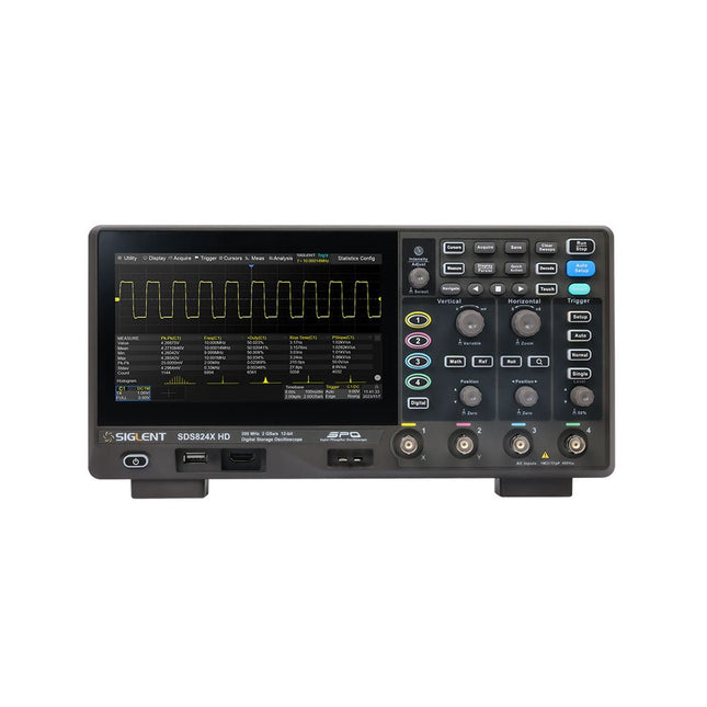
Siglent Siglent SDS814X HD 4-kanaals Oscilloscoop (100 MHz)
The Siglent SDS814X HD digital storage oscilloscope is based on 2 GSa/s, 12-bit Analog-Digital Converters and front ends with excellent noise floor performance. With a 100 MHz bandwidth, and a maximum record length of 50 Mpts, and the capability to analyze 4 analog channels alongside 16 digital channels, the SDS814X HD is perfectly suited for mixed signal analysis. Kenmerken 12-bit High Resolution 12-bit Analog-Digital Convertors with sample rate up to 2 GSa/s Front ends with 70 μVrms noise floor @ 100 MHz bandwidth 2/4 analog channels, up to 700 MHz bandwidth SPO technology Waveform capture rate up to 80,000 wfm/s (normal mode), and 500,000 wfm/s (sequence mode) Supports 256-level intensity grading and color temperature display modes. Up to 50 Mpts record length Digital trigger system Intelligent trigger: Edge, Slope, Pulse width, Window, Runt, Interval, Dropout, Pattern, Video (HDTV supported), Qualified, Nth edge, Delay, Setup/Hold time. Serial bus triggering and decoder, supports protocols I²C, SPI, UART, CAN, LIN. Segmented acquisition (Sequence) mode, dividing the maximum record length into multiple segments (up to 80,000), according to trigger conditions set by the user, with a very small dead time between segments to capture the qualifying event. History waveform record (History) function, the maximum recorded waveform length is 80,000 frames. Automatic measurements on 50+ parameters, supports statistics with histogram, track, trend, Gating measurement, and measurements on Math, History and Ref. 4 Math traces (2 Mpts FFT, addition, subtraction, multiplication, division, integration, differential, square root, etc.), supports formula editor. Abundant data analysis functions such as Search, Navigate, Counter, Bode plot and Power Analysis High Speed hardware-based Mask Test function, with Mask Editor tool for creating user-defined masks 16 digital channels (optional) 25 MHz waveform generator (optional) 7" TFT-LCD display with 1024 x 600 resolution; Capacitive touch screen supports multi-touch gestures. Interfaces include: USB Hosts, USB Device (USBTMC), LAN (VXI-11/Telnet/Socket), Pass/Fail, Trigger Out Built-in web server supports remote control over the LAN port using a web browser. Supports SCPI remote control commands. Supports external mouse and keyboard. Supports NTP. Specificaties Analog Channels 4 Bandwidth 100 MHz Vertical resolution 12-bit Sample rate (Max.) One channel mode: 2 GSa/sTwo channel mode: 1 GSa/sFour channel mode: 500 MSa/s Memory depth (Max.) One channel mode: 50 Mpts/chTwo channel mode: 25 Mpts/chFour channel mode: 10Mpts/ch Waveform capture rate (Max.) Normal mode: 80,000 wfm/sSequence mode: 500,000 wfm/s Trigger type Edge, Slope, Pulse width, Window, Runt, Interval, Dropout, Pattern, Video, Qualified, Nth edge, Delay, Setup/Hold time, Serial Serial trigger and decode (Standard) I²C, SPI, UART, CAN, LIN Measurement 50+ parameters, statistics, histogram, trend, and track supported Math 4 traces 2 Mpts FFT, Filter, +, -, x, ÷, ∫dt, d/dt, √, Identity, Negation, Absolute, Sign, ex, 10x, ln, lg, Interpolation, MaxHold, MinHold, ERES, Average. Supports formula editor Data analysis Search, Navigate, History, Mask Test, Counter, Bode plot, and Power Analysis Digital channel (optional) 16-channel; maximum sample rate up to 1 GSa/s; record length up to 10 Mpts USB AWG module (option) One channel, 25 MHz, sample rate of 125 MHz, wave length of 16 kpts, isolated output I/O 2x USB 2.0 Host, USB 2.0 Device, 10/100 M LAN, Auxiliary output (TRIG OUT, PASS/FAIL), SBUS (Siglent MSO) Probe (Standard) Passive probe PB470 for each channel Display 7 TFT-LCD with capacitive touch screen (1024x600) Inbegrepen 1x Siglent SDS814X Oscilloscope 4x Passive probe (100 MHz) PP510 1x Power cord (EU) 1x USB cable 1x Certificate of calibration 1x Quick start Downloads Datasheet Manual Programming guide
€ 586,85
-

Elektor Digital Elektor Maart/April 2020 (PDF)
De Elektor LoRa Nodeveelzijdige 868MHz-afstandsbediening met status-feedback, een groot bereik en een STM32 Interactiefcorrecties & updates || vragen & antwoorden Analoge elektronica ontwerpencase-study #1 – deel 2: de voorversterker voor de MEMS-microfoon My IoT-button: de knop voor het netdeel 1: IoT-architectuur BASIC voor ESP32/ESP8266programmeren met Annex WiFi RDS ESP32-deurbel via Telegram“de postbode belt maar één keer” Wie het kleine niet eert Beginnen met LoRaWANmet Blue Pill, LoRa-breakout-board en The Things Network “Een voorvechter van Open Internet”vraaggesprek met Wienke Giezeman, initiatiefnemer van The Things Network Meadow F7een board voor .NET-ontwikkelaars Multitasking met de ESP32 (2)taakprioriteiten Met de vos in het IoT (3)eerste stappen op het net Raspberry Pi Bash-commando cheat sheet De meest succesvolle start-up aanjager?HighTechXL, Eindhoven, Nederland Review: RPi-HAT Enviro+meet milieudata met Raspberry Pi en de Enviro+ HAT Uit het leven gegrepenonderdelen bestellen in Oekraïne en Rusland Review: Andonstar AD407beter dan zijn voorganger? Oost West Lab Besteen blik in het allerheiligste, waar onbevoegden geen toegang hebben... Optische probe voor de oscilloscoopmeet helderheidsvariaties van verlichtingssystemen Het TABULA-project: een updatetangibles met gebruikersfeedback Hoe... de maximale kortsluitstroom berekenenen de juiste zekeringautomaat te kiezen TMS1000-serie microcontrollersvreemde onderdelen Alle begin......hoeft niet zo moeilijk te zijn Developer’s Zonetips & trucs, vakkunstigheden en andere nuttige informatie Leidingen opsporenover het zoeken en vinden van onzichtbare en onderbroken leidingen Review: Joy-IT DMSO2D72 portable 3-in-1 oscilloscoop Doe-het-zelf PC voor het elektronicalabtips voor componentenkeuze en bouw De Elektuur 'Intelekt' schaakcomputer (1981)Tiny Chess-86 geport naar de Intel 8088 PCB-kunstverlegt de grenzen van industriële productie Hexadoku
€ 9,95
-
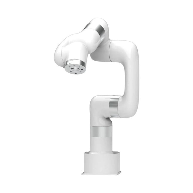
UFactory UFactory xArm 7
This multi-axis robot perfectly balances power and size. Features 6 Axis Payload: 3.5 kg Reach: 700 mm Repeatability: 0.1 mm Max Speed 1000 mm/s Applications Machine Tending Bin Picking Mobile platform Lab Automation Robotic Research Durable Collaborative robots for your automation Industrial-grade harmonic drive and servomotors guarantee 24/7 working without stop. Crafted from Carbon fiber, 15 kg weight makes it possible for easier deployment. Flexible deployment with safe feature Hand teaching, lightweight, space-saving and easy to re-deploy to multiple applications without changing your production layout. Perfectly for recurrent tasks. Collision detection is available for all of our cobots. Your safety is always the top priority. Graphical interface for beginner-friendly programming Compatible with various of operation systems, including macOS and Windows. Web-based technology compatible with all major browsers. Drag and drop to create your code in minutes. Powerful and open source SDK at your fingertips Fully functional open-source Python/C++ SDK provides more flexible programming. ROS/ROS2 packages are ready-to-go. Example codes help you to deploy the robotic arm smoothly. Specifications UFactory 850 xArm 5 xArm 6 xArm 7 Payload 5 kg 3 kg 5 kg 3.5 kg Reach 850 mm 700 mm 700 mm 700 mm Degrees of freedom 6 5 6 7 Repeatability ±0.02 mm ±0.1 mm ±0.1 mm ±0.1 mm Maximum Speed 1 m/s 1 m/s 1 m/s 1 m/s Weight (robot arm only) 20 kg 11.2 kg 12.2 kg 13.7 kg Maximum Speed 180°/s 180°/s 180°/s 180°/s Joint 1 ±360° ±360° ±360° ±360° Joint 2 -132°?132° -118°?120° -118°?120° -118°?120° Joint 3 -242°~3.5° -225°~11° -225°~11° ±360° Joint 4 ±360° -97°~180° ±360° -11°?225° Joint 5 -124°~124° ±360° -97°~180° ±360° Joint 6 ±360° ±360° -97°~180° Joint 7 ±360° Hardware Ambient Temperature Range 0-50°C Power Consumption Min 8.4 W, Typical 200 W, max 400 W Input Power Supply 24 V DC, 16.5 A Footprint Ø 126 mm Materials Aluminum, Carbon Fiber Base Connector Type M5x5 ISO Class Cleanroom 5 Robot Mounting Any End Effector Communication Protocol Modbus RTU(rs485) End Effector I/O 2x DI/2x DO/2x AI/1x RS485 Communication Mode Ethernet Included 1x xArm 5 robotic arm 1x AC control box 1x Robotic arm power cable 1x Robotic arm end effector adapter cable 1x Robotic arm signal cable 1x Control box power cable 1x Network cable 1x Mounting tool 1x Quick start guide
€ 14.569,00
Beste prijs
-

Elektor Digital Elektor 09-10/2025 (PDF) DE
Diese Ausgabe steht allen GOLD- und GREEN-Mitgliedern auf der ElektorMagazine-Website zum Download bereit! Sie sind noch kein Mitglied? Hier klicken! ESP32-Audio-Transceiver-Board (Teil 2)Drahtlose Audioübertragung Induktiver AM-SenderPIO des Pico in einem Arduino-Sketch Navigieren durch drahtlose ProtokolleEin technischer Leitfaden Satellitenverfolgung mit LoRaDas TinyGS-Netzwerk: Raumfahrtdaten gelangen zur Erde 4G-kompatible SMS-FernbedienungSteuern Sie Ihr Zuhause per Telefon aus der Ferne Hochgeschwindigkeits-TastkopfHochohmige Eingänge für Signale bis 200 MHz Aus dem Leben gegriffenKafka KrakenSDREin phasenkohärenter SDR-Empfänger Geschwindigkeitstests mit dem RP2350Lohnt sich der Umstieg von Raspberry Pi Pico 1 auf Version 2? Kontaktlose E-Feld-Messungen (2)Ein Laser-Vibrometer zur Erfassung der Membranschwingungen Quarze und OszillatorenQuarzgenauigkeit durch die Kondensatorwahl verbessern Aller Anfang ...... ist gar nicht schwer: Spezielle Audio-ICs Einstieg ins Programmieren von Selbstbauprojekten SPECTRAN® V6 MobileModular konfigurierbarer Echtzeit-Spektrum-Analyzer für zuverlässige Messungen in allen Frequenzbereichen Die Zukunft der KI wird in Silizium geschmiedetEin Interview mit Anastasiia Nosova Autonomer Sensorknoten v2.0 (Systemarchitektur)Solarbetriebene Sensorplattform mit integriertem GPS, LoRaWAN und weiteren Funktionen Präzise PositionsbestimmungBluetooth Channel Sounding ausprobiert Die Zukunft der Wireless-KommunikationDie ultradünnen Festkörperbatterien von BTRY Testgetriebene Programmierung in der Firmware-Entwicklung Handy-gesteuertes ModellautoWLAN + ESP32 + Smartphone = Fernsteuerung 2025: Eine KI-OdysseeKI-Denkmodelle: die Gedankenketten-Revolution Solarladeregler mit MPP-TrackingTeil 3: Software und Inbetriebnahme Web-Streaming-Kamera mit Raspberry Pi ZeroVerwendung des ZeroTier-VPN
€ 11,90
-

Elektor Digital Elektor May/June 2023 (PDF)
Elektor GREEN and GOLD members can download their digital edition here. Not a member yet? Click here. Knowledge for All! Super Servo TesterTest Up to Four Servos Stand-Alone or In-System Analog Signals and MicrocontrollersADCs, DACs, Current Measurement, and More embedded world 2023 Sub-Nyquist Sampling in PracticeReliably Capturing Higher Frequencies Using Subsampling Android Smartphone Here, ESP32 There?Practical Pproject Using the Android Wi-Fi API Active 1-kHz Filter for Distortion MeasurementBetter Measurements Through Optimization of the Measurement Signal Starting Out in Electronics......Multivibrating Cheerfully Further! Err-lectronicsCorrections, Updates and Readers’ Letters The New I3C ProtocolA Worthy Successor to I²C, or Just More Hot Air? BlueRC: IR Remote Control with Smartphone and ESP32Adaptive and Universal Microcontroller Documentation Explained (Part 2)Registers and Block Diagrams Automating Test and MeasurementProgramming Test Equipment to Do What You Want Infographics: Test and Measurement Overvoltage Protection for Safe OperationTransient Protection for Non-Isolated DC/DC Power Modules Wiha Measuring EquipmentReliable Electrical Testers and Meters Automating Testing and Collaborating on Test Results From Life’s ExperienceHigh-Level Electronics Energy LoggerMeasuring and Recording Power Consumption Assembling the 4tronix M.A.R.S. Rover Kit Parking Disk with E-Paper DisplayAn Innovative Digital Replacement eCO₂ Telegram botAir-Quality Measurement with Telegram Notification Behind the Scenes of DIY High-End AudioElektor’s Ton Giesberts Interviewed on the Fine Art of Analog Design HomeLab ToursWork in Progress... RFID Tag Reading and RFID Door LockSample Projects from the Elektor Arduino Experimenting Bundle Oscilloscope Current Probe for RFRF Current Measurements Made Easy Not for the Faint-Hearted: Robot Arm KitWith Raspberry Pi Pico and MicroPython Generative AIWho Made This Anyway? Hexadoku
€ 7,50
-

Elektor Digital Elektor Circuit Special 2024 PDF (FR)
Le téléchargement intégral de ce numéro est disponible pour nos membres GOLD et GREEN sur le site Elektor Magazine ! Pas encore membre ? Cliquez ici. charge électronique pour les tests à haute intensitéde la nécessité à l'innovation suppresseur de voixcircuit pour un karaoké instantané sélecteur audio A/B avec réglage de gaincommuter de l'entrée micro à l'entrée ligne optimiser la rechrage du LIR2032prenez soin de vos piles bouton la détection tactile en toute simplicitéun guide de fabrication pour n'importe quel microcontrôleur interrupteur universel à télécommandeune nouvelle vie pour les vieilles télécommandes une boite à meuh avec un microcontrôleurproduire des sons amusants à l'aide d'un microcontrôleur interface de batterie externe USB alimenter les appareils à faible consommation avec des batteries externesune Solution pour les maintenir actives mini-ampli audio de classe A avec sortie en courantpiloter les haut-parleurs en courant au lieu de tension module pseudo-symétriqueCMRR élevé avec des liaisons audio asymétriques chargeur automatique d'accu Ni-MHrechargez toutes vos batteries simultanément ! protection pour alimentation électrique basée sur un thyristor lecteur d'empreintes digitalesdispositif utile d'identification convertisseur de puissance DC-DC 3Aaméliorer vos sources de tension fixes innovations de la plateforme Arduino Project Hubnouveaux projets de la communauté contrôle à distance du chauffe-eaudétection de tension et de courant pour les lignes à courant alternatif atténuateurs pour signaux audio (1)sélection par cavaliers cure de jouvence pour votre vieux chargeur (1)ne le jetez pas, modernisez-le ! une carte pour « The Blue »circuit imprimé pour le potentiomètre motorisé d'Alps référence 50 Hz à partir d'une tension secteur 60 Hzconversion de 50 Hz à 60 Hz isolateurs numériquesréalisation facile de l’isolation galvanique amplificateur mono Hi-Fi compact de 12 Wpetit mais puissant générateur de rampe LM386 générateur triphaséavec Raspberry Pi Pico ouverture de porte pour les personnes ayant des talents musicaux classique d’Elektor : synthétiseur Surfgénérateur d’ambiance océanique relaxante (de Chhhh à Zzzz) cure de jouvence pour votre vieux chargeur (2)ne le jetez pas, modernisez-le ! surveillance du courant d'une lampe avec Raspberry Pi Pico télégraphie infrarouge Fnirsi SWM-10appareil portable de soudage par point intelligent pour réparer vos packs d’accumulateur Codec audio stéréo pour ESP32 et Ciela mesure audio : pas de panique techniques de soudure à l’étain faites-le correctement dès maintenant ! atténuateurs pour signaux audio (2) sélection par relais alimentation USB-CDrawing Power from USB-C Power Adapters trois circuits avec deux et trois puces 4017 comptez sur les 4017 composants actifs - la diode un minuteur pour des délais ultra-Longs réglez-le et oubliez-le ! Jack In & Jack Out maillon d’E/S pour chaînes audio alimenter un ESP32 à partir d'une seule cellule Li-ion Hexadoku
€ 10,95
-

Elektor Digital Elektor Circuit Special 2024 PDF (DE)
Diese Ausgabe steht allen GOLD- und GREEN-Mitgliedern auf der ElektorMagazine-Website zum Download bereit! Sie sind noch kein Mitglied? Hier klicken! Digitale Last für HochstromtestsVon der Notwendigkeit zur Innovation GesangsentfernerInstant-Karaoke-Schaltung Audio-Eingangswahlschalter mit VerstärkungseinstellungSchaltet von Mikrofon- auf Line-Eingänge um Ladeschaltung für LIR2032Optimierte Ladung = längere Haltbarkeit Touch-Sensing leicht gemachtEin DIY-Leitfaden für jeden Mikrocontroller Universeller Infrarot-FernschalterEin neues Leben für alte Fernbedienungen Mikrocontroller-gesteuerte MuhdoseBovine Klänge mit einem Mikrocontroller erzeugen USB-Batterieschnittstelle Stromversorgung von Low-Power-Geräten mit PowerbanksEine Stay-Alive-Lösung Kleiner Klasse-A-Audioverstärker mit StromausgangLautsprecher mit Strom statt mit Spannung ansteuern Pseudosymmetrisches ModulHohes Gleichtaktunterdrückungsverhältnis trotz asymmetrischen Audioverbindungen Automatisches Ladegerät für Ni-MH-ZellenFüllen Sie alle Ihre Akkupacks in einem Rutsch auf! Sicherheit durch thyristor-basierte Strombegrenzung Fingerabdruck-Sensor-SchalterEin nützliches Gerät zum Identitätsnachweis 3-A-GleichspannungswandlerBessere Nutzung Ihrer Festspannungsquellen Innovationen aus dem Arduino-Project-HubNeue Projekte aus der Community Fernkontrolle eines BoilersSpannungs- und Stromdetektion für Netzspannungsleitungen Abschwächer für AudiosignaleTeil 1. Einstellbar über Jumper Autobatterie-Ladegerät aufgemotztTeil 1. Wiederverwenden statt wegwerfen! Eine Platine für „The Blue One“Platine für Alps-Motorpotentiometer mit Rückmeldung 50-Hz-Referenz aus 60-Hz-NetzspannungWie man 50-Hz-Elektronik in 60-Hz-Umgebungen verwendet Digitale IsolatorenGalvanische Trennung einfach realisieren Kompakter 12-W-Hi-Fi-MonoverstärkerKlein, aber leistungsstark LM386-Rampengenerator DrehstromgeneratorMit Raspberry Pi Pico Türöffner für musikalisch Begabte Elektor-Klassiker: Surf-SynthesizerMeereswassersporthintergrundgeräuschgenerator (Mwsh3g) Autobatterie-Ladegerät aufgemotztTeil 2. Ladesteuerung analog und digital LampenstromüberwachungMit Raspberry Pi Pico Infrarot-Telegraphie Fnirsi SWM-10Reparatur von Batteriepacks mit tragbarem intelligentem Punktschweißgerät Stereo-Audio-Codec für ESP32 und Co.Keine Angst vor Audio-Messtechnik Die Kunst des LötensLötzinn-Techniken für einwandfreie Verbindungen Abschwächer für AudiosignaleTeil 2. Umschalten per Relais USB-C-PowerStrom aus USB-C-Netzteilen beziehen Drei Schaltungen mit zwei und drei Zähler-ICs4017-ICs im Zusammenspiel Aktive Bauelemente – Die Diode Timer für extrem lange VerzögerungenEinstellen und vergessen! Klinke rein, Klinke rausEine nützlicher Anschluss für Audioschaltungen ESP32 mit nur einer Lithium-Zelle versorgen Hexadoku
€ 11,90
-

Uni-Trend UNI-T UDP3305S-E DC-voeding (328 W)
The UDP3305S-E is a high-performance programmable linear DC power supply. It has a clear LCD user interface, excellent performance indicators, a variety of analysis functions and communication interfaces. It can meet the diversified test needs of users. It aims to provide cost-effective DC programmable power supply equipment for teaching, scientific research, industry and other fields. LCD interactive interface Using a 4.3-inch high-definition display screen, it provides users with a man-machine interface with rich functions and simple operation, which can display the current set output voltage/current, actual output voltage/current and protection output voltage/current value of the power supply in real time. The functional interface is simple and comprehensive, easy to operate. One-key setting for series and parallel The series-parallel connection between CH1 and CH2 of the main channel can be realized without external connection, which simplifies the connection and makes the test easier. List/Delayer function With list and delay setting functions, it can set up to 2048 sets of data according to test requirements, and the number of cycles can reach 99999. It is used with waveform templates, which is very convenient for cycle testing and aging testing. Rich remote control interface Standard RS232 communication interface, Ethernet interface, Digital I/O and master and slave USB interfaces, can be controlled by remote connection to Ethernet, or through RS232 and USB, with the host computer software to achieve software control. Specificaties Type Linear DC power supply Channels 4 Total power 328 W Output voltage CH1/CH2: 0~30 VCH3: 0~6 VCH4: 5 V Output current CH1/CH2: 0~5 ACH3: 0~3 ACH4: 2 A Resolution 10 mV, 1 mA Setting accuracy 0.3% +20 mV<0.2% +5 mA Connectivity USB Device, RS-232, LAN, USB host, Digital I/O Inbegrepen 1x UDP3305S-E DC Power Supply 1x Power cord 1x USB cable Downloads Datasheet User manual Programming manual Software V1.0 Firmware V1.10
€ 396,54


