
Zoekresultaten voor "raspberry OR pi OR 500 OR de"
-

Elektor Digital Elektor July/August 2025 (PDF) EN
Elektor GREEN and GOLD members can download their digital edition here. Not a member yet? Click here. OBD2 Sensor DashboardOld Dials Sparked a Quest for Real Data OBD2: Add a Rev Counter and Gear Shift Indicator to Your CarRetro, but Super Useful LiDAR and Vision Sensors for Robotics Sensor+Test 2025 and PCIM 2025 Contact-Free E-Field Measurements (1)A Vibrating Membrane for Assessing DC Voltages or Static Electric Fields Wireless Mailbox NotifierFrom Optical Sensors to Radar, Exploring a Few Options Elektor Mini-WheelieA Self-Balancing Robot Solar CellsPeculiar Parts, the Series Getting Started With a Modern Radar SensorIs an Accurate Measurement on Your Radar? From Life’s ExperiencePaper Factory CybersecurityTough Times for Hackers Siglent Presents Next-Gen Multi-Channel OscilloscopesHigh-Performance Solutions for Modern Power and Embedded Systems Bluetooth 6.0 Brings Enhanced Distance-Ranging ApplicationsNew Version Offers Improved Device Positioning and Location Services Exploring Wireless Communication with BeagleY-AI Err-lectronicsCorrections, Updates, and Readers’ Letters Starting Out in Electronics……Concludes the Topic on Opamps A Powerful AI Code AssistantSpeed Up Your Development with Continue and Visual Studio Code Solar Charge Controller with MPPT (2)The Circuit Ultrasonic Obstacle DetectorA Simple Project to Help Those with Impaired Vision 2025: An AI OdysseyMid-Year Review Raspberry Pi Standalone MIDI Synthesizer (3)Making It Smarter and Adding a User Interface Meshtastic: A Demo ProjectAn Intelligent Mesh of LoRa Radios Analog Audio Frequency GeneratorHigh-Quality Adjustable Frequency Sine Wave Generator
€ 7,50
-

Elektor Digital Elektor May/June 2024 (PDF)
Elektor GREEN and GOLD members can download their digital edition here. Not a member yet? Click here. STM32 Wireless Innovation Design Contest Winners In-Circuit LC MeterA Prototype Study The AmpVolt Modular DC Power Meter (Part 1)Measure DC Power and Energy Consumption Up to 50 V and 5 A embedded world 2024 Repairing Electronic EquipmentTools, Techniques and Tips Starting Out in Electronics…...Continues the Opamp Theory A Simple DDS Signal GeneratorDirect Digital Synthesis in Its Purest Form Sparkplug at a GlanceA Specification for MQTT Data The CRTCPeculiar Parts, the Series Radar-Controlled LightingAutomatic Stairway Light With Human Presence Detection Digital Bubble Level and Active Stroboscopic Disc for TurntablesFine-Tune Your Record Player With This All-In-One Tool Open Source and Its Significance for the Electronics Industry (2) M12 Circular Connector With A-codingFirst Choice for Industrial Applications The Arduino-Inside Measurement LabAn 8-in-1 Test & Measurement Instrument for the Electronics Workbench Sound Card Performs Gain/Phase and Impedance AnalysisFor Frequencies From 100 Hz to 90 kHz Measuring pH Value With the Arduino UNO R4Check the Quality of Your Water From Life’s ExperiencePangpong Butt Launcher FNIRSI 1014D Digital Storage OscilloscopeGood Performance for Tight Budgets 2024: An AI OdysseyGetting Object Detection Up and Running 10 MHz Reference GeneratorHighly Accurate, With Distributor and Galvanic Isolation Project Update #2: ESP32-Based Energy MeterSome Enhancements Err-lectronicsCorrections, Updates, and Readers’ Letters An Interview with Eben Upton, CEO of Raspberry PiRaspberry Pi 5 and Beyond
€ 7,50
-

Sensepeek Sensepeek 6024 SQ500 (500 MHz handsfree Oscilloscope Probe)
The SQ series of handsfree probes from Sensepeek have a lower point of gravity making them even more stable compared with the original SP series of handsfree probes. All probes in the SQ series are also insulated and can be used handheld as any traditional probe but their full potential is used when measuring handsfree. The SQ series of oscilloscope probes also includes more ground options, have probe tip protection, longer cable and support for oscilloscopes with automatic scaling (10:1). All the loved features of handsfree measurement, exchangeable fine pitch spring tipped test needle, color-coded cable holders and the minimalistic design is maintained to make traditional sized and handheld probes obsolete. Both length and weight of the SQ probes are perfectly balanced to be used with PCBite PCB holders and base plate which is a must for handsfree function. Features Passive 10:1 probe with support for oscilloscopes with automatic scaling Spring-loaded test needle for fine pitch measurements Multiple ground options Color coded cable holders Probe tip protection Insulated, can be used handheld Improved probe holder for handsfree measurement when used with PCBite PCB holders Included 1x SQ500 500 MHz probe with spring tipped test needle 1x SQ probe holder for handsfree measurement 1x Testhook with detachable cables (5 cm & 10 cm) for convenient ground connection 1x Alligator cable for convenient ground connection 1x Standard ground spring, for handheld measurements at rated bandwidth 1x Unique ground spring, for total handsfree measurements at rated bandwidth 1x Set of color coded cable holders (4 colors) 1x Probe tip protection 1x Extra test needle Downloads User Guide SQXX0 Rev1.1
€ 131,89
-

Elektor Digital Elektor May/June 2022 (PDF)
Your First Steps with an ESP32-C3 and the IoTA Wi-Fi Button and Relay IoT Cloud a la Arduino Dual Geiger-Müller Tube Arduino ShieldA High Sensitivity, Very Low-Power Radiation Sensor CO2 GuardA DIY Approach to Monitoring Air Quality MonkMakes Air Quality Kit for Raspberry PiMeasures Temperature and eCO2 Starting Out in ElectronicsWelcome to the Diode Tips & Tricks for Testing ComponentsNo Expensive Equipment Required Reducing the Power Consumption of Your Mole RepellerAn ATtiny13 Replaces a 555 Light Switch DeLuxA Solution for High-Precision Light-Controlled Switching The Challenges in Bringing IoT Solutions to MarketWorries Around Security, Scalability, and Competition Infographics 5-6/2022 Preferably Wired After AllTips for Developing a 1 Gbit/s Interface in an Industrial Environment Bringing Real-Time Object Detection to MCUs with Edge Impulse FOMO Traveling-Wave TubesPeculiar Parts, the Series Narrowband Internet of ThingsStandards, Coverage, Agreements, and Modules Dragino LPS8 Indoor GatewaySpeedy LoRaWAN Gateway Setup Explore ATtiny Microcontrollers Using C and Assembly LanguageSample Chapter: ATtiny I/O Ports Err-lectronicsCorrections, Updates and Readers’ Letters LoRa GPS Tracker UpdateReceive and Show Location Using a Raspberry Pi Circuit Simulation with TINA Design Suite & TINACloudSample Chapter: Sinusoidal Oscillators From Life’s ExperienceAssembly Line Work The WinUI Graphics Framework for Windows AppsA Small Demo Application GUIs with PythonWorst GUI of the world Off-Grid Solar SystemsElectrical Energy Independent of the Mains Grid The 10-Year SmartphoneRenew Your Expectations HexadokuThe Original Elektorized Sudoku
€ 7,50
-

Elektor Edge Impulse Guest Edition 2025 (DE)
Diese Ausgabe steht allen GOLD- und GREEN-Mitgliedern auf der ElektorMagazine-Website zum Download bereit! Sie sind noch kein Mitglied? Hier klicken! Was genau ist eigentlich Edge-KI?Intelligenz direkt im Gerät Wir stellen vor: Edge Impulse StudioKI-Modelle für Edge-Geräte einfach erstellen und bereitstellen Keyword Spotting mit Edge ImpulseErfassen, Trainieren und Implementieren Intelligente Gerätesteuerung per Sprachbefehl mit Nordic Thingy:53 Edge-KISchlüsselbegriffe zum Verständnis von Edge-KI und Machine Learning Crashkurs: Einstieg in Edge ImpulseWie Sie mit dem Arduino Nano 33 BLE Sense ein ML-Modell erfassen, trainieren und bereitstellen Ein neues Kapitel für ArduinoVom Hobby-Board zur Edge-Computing-Plattform Erste Schritte mit Objekterkennung auf Edge-Geräten Fehlererkennung auf LeiterplattenComputer Vision mit dem Raspberry Pi KI-Skalierung für kleinste Geräte Optimierung der Energieeffizienz bei batteriebetriebenen Edge-KI-Geräten KI-ToasterWenn Edge-KI das Frühstück rettet Thundercomm Rubik Pi 3Raspberry Pi trifft Edge-KI Unternehmensführung, Embedded ML und die Edge-Revolution Vision-Language-Modelle für Edge-GeräteKaskadierte Modelle für höhere Zuverlässigkeit Lernen Sie Edge Impulse kennenFragen aus der Elektor-Community Projekt-Update #5: Energiemessgerät mit ESP32Haushaltsgeräte mit Edge-KI erkennen Bewegungserkennung mit Anomalie-ErkennungEin End-to-End-Tutorial Intelligentes Belüftungssystem: Verbindung von Schall- und UmweltdatenEin Dual-MCU-Ansatz mit Machine Learning für die automatische Steuerung von Fenstern und Jalousien Sprachsteuerung für Ohrhörer und Headsets Edge-KI: Intelligente Geräte auf dem Vormarsch
€ 15,90
-

Elektor Digital Elektor November/December 2023 (PDF)
Elektor GREEN and GOLD members can download their digital edition here. Not a member yet? Click here. The Raspberry Pi 5A Huge Improvement From Its Predecessor AI in the Electronics LabGoogle Bard and Flux Copilot Put to the Test Arduino Nano Waveform GeneratorNano + Code = Function Generator Solar-Powered Christmas GarlandAn Eco-Friendly Solution for Garnishing Your Balcony USB Killer DetectorBetter Safe Than Sorry A Simple CNCed EnclosureWith Autodesk Fusion 360 for Personal Use Low-Volume Board ProductionWith and without Assembly IoT Simulation Simplified with WokwiDeveloper Uri Shaked on Design, Software, and More A Bare-Metal Programming Guide (Part 3)CMSIS Headers, Automatic Testing, and a Web Server LoRa, a Swiss Army Knife (2)The Hardware and Software MEMS Microphone Design and Construction Tools to Try Before You SolderSimulation and 3D Modeling Tools That Can Be Used for Free New Tools From Microchip!PICkit 5 and MPLAB ICD 5 Available Now! Rapid Prototyping of Flexible, Stretchable ElectronicsHow the Voltera NOVA Speeds Up Innovation in Wearable Electronic Systems Galvanic IsolationUsing Phototransistor Optocouplers Successfully The Complex Solution or the Anybus Solution?Embedded Industrial Ethernet in 2 Days Rather Than Many Months Your Essential DFM ChecklistHow to Start Designing for Manufacture 3D Printing FilamentsTypes, Features and Use in Prototyping Specialists for Effective Signal Analysis from ELF to EHF BandAaronia’s latest real-time SPECTRAN® V6 series spectrum analyzers Challenges of DFM Analysis for Flex and Rigid-Flex Design Setting Up an SMT Line The Right Combination for a Reliable Assembly Revolutionizing IndustriesThe Rise of Autonomous Mobile Robots (AMRs) Evolved for More ChallengesRohde & Schwarz Adds Eight-Channel R&S MXO 5 to Next-Generation Oscilloscopes Starting Out in Electronics……Amplifying Differences Mini Reflow PlateFor Assembling or Repairing Small SMD Circuits Don’t Start with a Prototype – Start with a Pretotype!Check That a Market Exists for Your Product Before Warming Your Soldering Iron 2023: An AI OdysseyGetting Help Designing a Physical Project Brussels Is InnovatingSupport for Deep Tech
€ 7,50
-
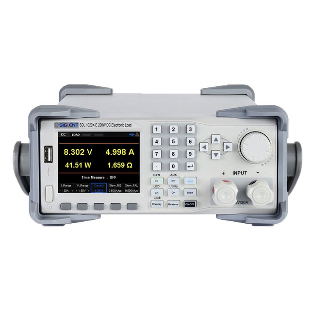
Siglent Siglent SDL1020X-E DC Electronic Load (200 W)
De Siglent SDL1020X-E DC meetsnoeren hebben een meetresolutie van 0,1 mV/0,1 mA en de basis SDL1000X-E serie heeft een resolutie van 1 mV/1 mA en instelbare stroom flankstijgtijden van 0,001 A/?s~2,5 A/?s. Voor communicatie en bediening op afstand bevat de SDL serie S232/USB/LAN interfaces. De SDL1020X-E levert stabiliteit over een breed scala van toepassingen en kan aan allerlei test vereisten voldoen. o.a: Voeding, batterij/handapparaat ontwerp, industrie, LED verlichting, auto-elektronica, en ruimtevaart. Kenmerken SDL1020X-E (één kanaal): DC 150 V/30 A, totaal vermogen 200 W 4 Statische modes / Dynamische mode: CC/CV/CR/CP CC Dynamische stand: Continu, gepulseerd, omgeschakeld CC Dynamische stand: 25 kHz, CP Dynamische stand: 12,5 kHz, CV Dynamische modus: 0,5 Hz Meetsnelheid van spanning en stroom: tot 500 kHz Instelbaar bereik van de stijgtijd van de stroom: 0,001 A/us~2,5 A/us Min. afleesresolutie: 0,1 mV, 0,1 mA Kortsluit-, batterijtest-, CR-LED modus-, en fabriekstestfuncties 4-draads SENSE compensatie mode functie List functie ondersteunt het bewerken van wel 100 stappen Programmeerfunctie ondersteunt 50 groepen stappen OCP, OVP, OPP, OTP en LRV beveiliging Externe analoge regeling Spanning, stroom bewaking via 0-10 V 3,5 inch TFT-LCD scherm, geschikt voor gelijktijdige weergave van meerdere parameters en toestanden Ingebouwde RS232/USB/LAN communicatie interface, USB-GPIB module (optioneel) Trendgrafiek van golfvormen en gemakkelijk te gebruiken functies voor het opslaan en oproepen van bestanden Inclusief PC software: Ondersteunt SCPI, LabView aandrijving Inbegrepen 1x Siglent SDL1020X-E DC programmeerbare belasting 1x Snelstartgids 1x Garantiekaart 1x Netsnoer 1x USB kabel Downloads Datasheet Manual Programming Guide PC Software
€ 531,19
-

Elektor 07-08/2026 (DE)
Diese Ausgabe steht allen GOLD- und GREEN-Mitgliedern auf der ElektorMagazine-Website zum Download bereit! Sie sind noch kein Mitglied? Hier klicken! MultiRF-EntwicklungsboardEine Plattform zur Evaluierung drahtloser Protokolle für kurze und lange Reichweiten Elektor wird 65Elektronik im Wandel seit 1961 WLAN-basierte Personenerkennung mit dem ESP32Wenn der Router zum Bewegungsmelder wird Drahtlose WaagenVier kleine Waagen = eine große Waage Walter, das kompakte IoT-ModulESP32-S3-SoC, LTE-M/NB-IoT-5G-Modem und GNSS-Receiver 3- und 4-Draht-RTD-Sensoren konditionierenMit Vollbereichsabgleich und Kabelkompensation Drei in einem: 2-Kanal-Oszilloskop/Generator/MultimeterEin Test des Fnirsi 2D15P electronica Fast Forward 2026 für Start-ups und Industriepartner EcologgingEine modulare IoT-Messstation für Umweltdaten Drahtlos-Anbindung für MedizingeräteImmer am Puls mit Bluetooth LE AudiotronicsBrummunterdrückung Mehr Effizienz in der Landwirtschaft durch KI-Modelle und SensorenSteigerung der landwirtschaftlichen Produktivität OPC UA – ein ÜberblickPlattformunabhängiger Datenaustausch Redox-Meter Instrumentenverstärker für Physik- und Engineering-Experimente Aktive differentielle Audio-FilterFür professionelle Frequenzweichen und mehr Elektor-Community-Tipps zu IoT und Sensoren Telegram-gesteuerter WarmwasserbereiterEine Lösung mit ESP32 und Arduino-Software 2026: Eine KI-OdysseeWas wurde eigentlich aus der Fuzzy-Logik? Projekt 2.0 Alarmsignalinjektor + PowerTools zum Suchen verdeckt verlegter Leitungen
€ 15,90
-

Elektor Publishing Software Defined Radio zum Selbstbau
Praktischer Einstieg mit Arduino, GnuRadio und FPGA Das Thema „Software Defined Radio“ ist facettenreich: Neben der Schaltungstechnik ist auch eine Einarbeitung in die Programmierung von Hardware und PC wichtig. Ein schrittweises Vorgehen erleichtert Ihnen den Einstieg. Mit dem im Buch vorgestellten modularen „RF Bricks“-Konzept werden Sie zum Architekten Ihrer Signalkette. Auf einem Chassis angeordnet gewährleisten die Module einen soliden und gut abgeschirmten Aufbau, den Sie einfach verändern und mit eigenen Ideen anreichern können. Der skalierbare Aufbau bildet Ihr Blockschaltbild auch mechanisch ab – die so gewonnene Übersicht kann in der Aus- und Weiterbildung nützlich sein. Ein Arduino in Ihrem Chassis kommuniziert nach einigen Anpassungen mit üblichen SDR-Programmen, z. B. SDRCPP, GQRX und CubicSDR auf einer Linux-Plattform. Damit können Sie Ihren Empfänger direkt per Mausklick abstimmen. Wenn Sie Blockschaltbilder mögen, ist GnuRadio ein natürlicher Partner der „RF Bricks“. Mit einem selbst programmierten Python-Block gelingt Ihnen in GnuRadio die Fernsteuerung Ihres Empfängers. Im GnuRadio-Universum können Sie Ihre GUI stufenweise ausbauen, behalten dabei aber immer volle Kontrolle über die inneren Abläufe des Programms. Mit einem FPGA können zeitaufwändige Operationen auch direkt in die Hardware verlagert werden. Sie bauen stufenweise einen Doppelsuperhet auf und entwickeln die Filterkoeffizienten für FIR-Filter mit Scilab. Das in VHDL realisierte Weaver-Schema rundet diesen Empfänger ab, der mit hoher Empfindlichkeit und Dynamik aufwarten kann. Mit dem gewonnen Überblick und Ihrer neuen Hardware können Sie die einzelnen Aspekte des Themenkomplexes SDR beliebig weiter vertiefen. Downloads Software
€ 44,80
Beste prijs
-

Elektor Labs Elektor Low-noise Labvoeding
De low-noise labvoeding van Elektor is een volledig analoge, instelbare, symmetrische unit met gemiddeld vermogen, zonder schakelende of digitale componenten. De uitgangsspanning is instelbaar tussen 0 V en ±22 V, en de uitgangsstroom kan worden ingesteld van 0 A tot 1 A. Doordat elke vorm van schakeltechniek wordt vermeden, levert het ontwerp extreem weinig ruis. Voor de weergave van beide uitgangsspanningen en -stromen worden vier kleine analoge paneelmeters met draaispoel gebruikt. De meeste moderne laboratoriumvoedingen en AC-adapters maken gebruik van schakelende technieken. Zelfs de beste uitvoeringen vertonen onvermijdelijk hoogfrequente rimpel en andere schakelartefacten op hun uitgang, die het testen van gevoelige analoge schakelingen kunnen verstoren en metingen van kleine signalen kunnen beïnvloeden. Om dit te voorkomen, is het concept hier een volledig analoge voeding. Hoewel deze minder efficiënt is dan vergelijkbare schakelende voedingen, is de lagere efficiëntie bij gebruik op de testbank nauwelijks van belang en zorgt deze voor schonere en betrouwbaardere meetresultaten. Omdat veel analoge schakelingen een symmetrische voeding vereisen, levert dit ontwerp positieve en negatieve uitgangsspanningen van gelijke grootte. Een kleine hoeveelheid afregeling is beschikbaar om eventuele onbalans te compenseren. Uiteraard is ook een instelbare stroombegrenzing aanwezig. De kit bevat de onderdelen die nodig zijn om de voeding te bouwen, met uitzondering van de transformatoren. Specificaties Uitgangsspanning 0…+22 V, 0, −22 V Uitgangsstroom 0…+1 A, 0…−1 A Ruis −85 dBV (bij 0,95 A/20 V, B = 22 kHz) −84 dBV (bij 0,95 A/20 V, B > 500 kHz) Rimpelspanning 50 µVRMS (bij 950 mA/20 V, B = 22 kHz, voornamelijk 100-Hz-component) Inbegrepen 3x printplaten: regelaar (PCB-1), netfilter (PCB-2) en transformator (PCB-3) Alle componenten, behalve de AC-transformatoren 4x draaispoelmeters Extra onderdelen voor de bedrading (draden, banaanstekkerbussen, IEC-voedingsmodule, enz.) Niet inbegrepen De drie AC-transformatoren Een behuizing Onderdelenlijst Voor de regelaar-printplaat (240386-1) Weerstanden (250 mW, 1%) R1 = 12 Ω R2, R8, R37, R62 = 1 MΩ R3, R7, R10, R13, R17, R20, R22, R30, R35, R42, R45, R47, R55, R60 = 100 Ω, 600 mW R4, R5 = 4.7 kΩ R6 = 100 kΩ R9, R12, R14, R36, R38, R39, R61, R63, R66, R72, R78, R79 = 10.0 kΩ, 600 mW R11 = 9.76 kΩ, 600 mW R15, R40 = 44.2 kΩ, 600 mW R16, R41, R77 = 1 kΩ R18, R43 = 1.5 kΩ, 1 W, 5% R19, R44 = 470 Ω, 1 W, 5% R21, R46 = 330 Ω, 600 mW R23, R24, R48, R49 = 1.0 Ω, 1 W R25, R50 = 1 kΩ, 1 W, 5% R26, R28, R51, R53 = 1.000 kΩ 0.1%, 15 ppm/C R27, R29, R52, R54 = 10.00 kΩ 0.1%, 15 ppm/C R31, R56 = 1.2 kΩ, 1 W, 5% R32, R57 = 47 kΩ R33, R58 = 270 Ω R34, R59 = 27 kΩ R64, R69 = 12.0 kΩ R65 = 3.0 kΩ, 600 mW R67, R80 = 470 Ω, 600 mW R68, R70 = 6.8 kΩ, 600 mW R71 = 30.0 kΩ,, 600 mW R73, R74, R75, R76 = 10 MΩ P1, P2, P3 = 10 kΩ, 200 mW, 20%, potentiometer, 1 turns, single, lin., panel mount P4, P5 = 500 Ω, 500 mW, 10%, trimmer, 25 turns, 3296Y-1-501LF Bourns P6, P7 = 10 kΩ, 500 mW, 10%, trimmer, 25 turns, 3296Y-1-501LF Bourns Condensatoren C1 = 100 nF, 50 V, 10%, ceramic X7R, LS 5 mm C2, C3, C6, C7, C30 = 10 µF, 63V, 20%, LS 2.5 mm, 3000hours@105°C C4, C5, C8, C9, C13, C14, C18, C19, C23, C24, C28, C29, C31, C32, C38, C39 = 100 nF, 250 V, 10%, PET, LS 7.5 mm C10, C20 = 47 nF, 100 V, 5%, PET, LS 5 mm C11, C21 = 10 nF, 100 V, 5%, PET, LS 5 mm C12, C22 = 220 µF, 35 V, 20%, 0.024 Ω, LS2.5/3.5 mm, Ir 3.4 A, 2000hours@125°C, polymer C15, C25 = 120 µF, 50 V, 20%, ESR 0.02 Ω, Diam. 10 mm max., LS 5 mm C16, C26 = 15 nF, 100 V, 5%, PET, LS 5 mm C17, C27 = 47 nF, 100 V, 5%, PET, LS 5 mm C33, C34 = 22 µF, 50 V, 20%, LS 2 mm, 10000 hours @ 105°C C35, C36, C44, C45 = 1 µF, 100 V, 10%, LS 5 mm, ceramic X7R C37 = 100 uF, 50 V, 20%. LS 3.5 mm C40, C41, C42, C43, C46, C47, C48, C49 = 1000 µF, 50 V, 20%, LS 5/7.5 mm, Ir 3.32 A, 10000hours@105°C, D 16 mm C50, C51, C52, C53 = 47 nF, 100 V, 10%, ceramic X7R, LS 5 mm Spoelen L1, L2 = 4.7 µH, 3.2 A, 0.033 Ω, LS 5 mm, RLB0914-4R7ML Bourns L3 = Commom mode choke, 14.5 mH, 3 A, SSRH24NH-30145 Kemet Halfgeleiders D1, D2, D3, D4, D5, D9, D10, D11, D15 = BAT85, DO-34 D6, D7, D12, D13 = SR560, DO-201AD D8, D14, D16 = 1N4148, DO-35 D17 = Zenerdiode, 5.6 V, 0.5 W, DO-41 D18, D19 = 1N4004, DO-41 D20, D21 D22, D23 = V30100CI-M3/P, dual common cathode, TO-220 D24 = Zener diode, 30 V, 1 W, DO-41 LED1, LED2 = LED, red, T-1 (3 mm) LED3, LED4 = LED, green, T-1 (3 mm) TVS1, TVS2 = BZW50-33B, R6 T1, T2, T4 = BC337.25, TO-92 T3 = NJW0302G, TO-3P T5, T6, T8 = BC327.25, TO-92 T7 = NJW0281G, TO-3P T9 = BD139, TO-126 (SOT-32) IC1 = LM334Z, TO-92 IC2 = LM4040AIZ-5.0/NOPB, TO-92 (TO-226AA-3) IC3, IC4 = OPA2992IDR, SOIC-8 IC5, IC6 = OPA4992IDR, SOIC-14 IC7 = OPA992IDBVR, SOT-23-5 IC8 = LM339N, DIP-14 IC9 = LM317, TO-220 IC10 = LM337, TO-220 Overige F1, F2 = 5×20 mm fuse, 1.6 A, fast acting HS1, HS2 = Heatsink MC33271 (for T3/T7), 2.7°C/W, PCB mount, height 63.5 mm K1, K4 = 3-way screw terminal block, LS 3.5 mm, max. 1.5 mm² K2, K3 = 3-way screw terminal block, LS 3.5 mm, max. 1 mm² M1, M3 = Moving coil meter, Range 30 V, type 91C4, 45×45 mm M2, M4 = Moving coil meter, Range 1 A, type 91C4, 45×45 mm² RE1 = Relay DPDT,5V, UA2-5NU Diversen 3× 3-way screw terminal block, LS 3.5 mm, max. 1 mm² (for P1, P2, P3) 4× Pin header, 1×2, vertical, pitch 2.54 mm (for LED1, LED2, LED3, LED4) 4× Pin socket, 1×2, vertical. pitch 2.54 mm (for LED1, LED2, LED3, LED4) 2× Heatsink FK222SA220, 20°C/W, PCB mount (for IC9 & IC10) 2× Mica thermal pad for TO-220, 12×18×0.05 mm (for IC9 & IC10) 2× Insulating bushing IB 6, TO-220 (for IC9 & IC10) 2× Ceramic thermal pad, 23×20×2 mm (for T3 & T7) 2× PCB Fuse Holder, for 5×20 mm fuse, 10 A (for F1, F2) 2× Cover for PCB Fuse Holder, transparent (for F1, F2) 2× 2-way screw terminal block, LS 3.5 mm, max. 1 mm² (for M1 & M3) 2× 2-way screw terminal block, LS 3.5 mm, max. 1.5 mm² (for M2 & M4) 8× M3 solder lug, thickness 0.35 mm (for M1…M4) M4 solder lug, thickness 0.35 mm (to connect 4 mm banana connectors) Screened cable, 1 pair, 2×24 AWG/0.22 mm², 1 m (for P1, P2 & P3) IC socket, DIP, 14 contacts (for IC8) M3 washer, plain, steel M3 screw, 16 mm, steel, pan head M3 nut M3 spring washer 50 mm M3 standoff, steel, male-female 12 mm M3 standoff, steel, male-female 10 mm M3 standoff, steel, male-female M3 screw, 8 mm, steel, pan head Voor de netfilter-printplaat (240386-2) Weerstand R1 = 220 kΩ, 1 W, 500 V, 5% Condensatoren C1, C2 = 470 nF, 305 VAC, Class X2, 11 × 27 mm max., LS 15/22.5 mm C3, C4, C5, C6 = 2.2 nF, 300 VAC, Class Y2, 13 × 4 mm, LS 10 mm, PP Spoelen L1, L2 = Common-mode choke, 6.8 mH, 1.7 A, TDK B82732R2172B030 Halfgeleider MOV1 = TVS varistor, 300 VAC, S14K300 (230 VAC, B72214S0301K101) and SK14K150 (150 VAC, B72214S0151K101) Overige K1, K2 = 3-way screw terminal block, LS 7.62 mm F1 = Time-delay fuse, 0.5 A (230 VAC) or 1 A (115 VAC) Diversen 1× Fuse holder, 5×20 mm, 10 A, 500 VAC 1× Transparent fuse cover 4× 10 mm M3 standoff, steel, male–female 4× M3 screw, 8 mm, steel, pan head 4× M3 nut Voor de transformator-printplaat (240386-3) Weerstanden R1, R2 = 2.7 kΩ, 600 mW, 1% R3 = 10.0 kΩ, 600 mW, 1% Condensator C1 = 220 µF, 50 V, 20%, Ø10 mm, LS 5 mm, 4000 h @ 105°C Transformatoren (niet inbegrepen in deze kit!) TR1, TR2, TR3 = 2×7 V, 25 VA, PCB-mounted toroid, 70060K Talema Halfgeleiders D1–D4 = 1N4148, DO-35 D5, D6 = 1N4004, DO-41 D7 = Zener 5.6 V, 1.3 W, DO-41 LED1 = LED, red, T-1 (3 mm) IC1, IC2 = MOC8021M, CTR ≥ 1000%, DIP-6 Overige F1, F2, F3 = 160 mA time-delay fuse (230 VAC) or 315 mA time-delay fuse (115 VAC) K1 = 2-way screw terminal block, LS 7.62 mm K2 = 3-way screw terminal block, LS 3.5 mm, max 1.5 mm² K3, K4 = 3-way screw terminal block, LS 3.5 mm, max 1 mm² RE1, RE2 = Relay DPDT, 5 A/250 VAC / 24 VDC Diversen 1× Pin header 1×2, pitch 2.54 mm + matching socket for LED1 3× Fuse holder 5 × 20 mm, 10 A, 500 VAC + transparent cover 3× M4 screw, 8 mm, pan head + washer for TR1-TR3 8× M3 screw, 8 mm, pan head + nut + washer 8× 10 mm M3 standoff, steel, male–female 2× IC socket, DIP-6 for IC1 & IC2 Extra onderdelen 1 m red insulated wire, stranded, 1.5 mm² 0.5 m blue insulated wire, stranded, 1.5 mm² 0.5 m black insulated wire, stranded, 1.5 mm², 0.5 m 2 m red insulated wire, stranded, D 0.56 mm (0.25 mm²) 2 m black insulated wire, stranded, D 0.56 mm (0.25 mm²) 0.5 m Multicore Cable, Flexible, 3 Core, 0.75 mm² (24 x 0.2 mm) Red banana socket Black banana socket Blue banana socket Green banana socket IEC Power Entry Module with switch, IEC C14 3 crimp terminals, FASTON, 4.75 x 0.81 mm 3 knobs Links Elektor Labs JumpStarter Page Artikel (deel 1) Artikel (deel 2)
€ 299,00€ 249,00Beste prijs
-
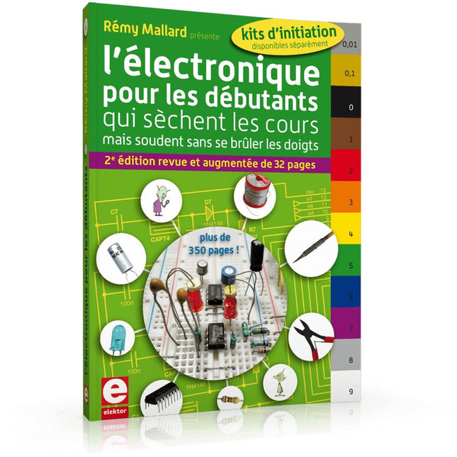
Elektor Publishing L'électronique pour les débutants
... qui sèchent les cours mais soudent sans se brûler les doigts Par où commencer pour débuter en électronique ? Vais-je m'égarer en explorant l'internet ? Il regorge de schémas, mais sont-ils fiables ? Me faut-il un livre avec des montages simples ou plutôt un livre sur les composants ? Après trente ans de pratique, l'auteur de ce livre, resté l'éternel débutant qui réalisait lui-même son premier montage des l'âge de dix ans, partage ici sa soif toujours vive d'apprendre. Fin pédagogue, il guide les débutants et répond aux questions que trop de livres laissent en suspens : « Quel type de fer à souder acheter ? »... « Un multimètre à 5 € peut-il suffire ? »... « Un oscilloscope est-il indispensable ? »... « Peut-on installer son montage dans une boîte à cigares ? »... Rémy Mallard démystifie l'électronique en n'utilisant que ce qu'il vous faut de théorie pour aborder joyeusement la pratique sans risque de faire de grosses bêtises. Vous apprendrez à identifier les composants et leur rôle (résistances, condensateurs, bobines, diodes, transistors, relais, commutateurs...) mais aussi à les récupérer, les tester et les ranger. Bientôt vous saurez lire un schéma, choisir vos outils et mettre en boîte vos montages. Rémy connaît toutes les astuces et vous révèle les pratiques à éviter. La matière de cet ouvrage, ce sont des montages simples et ludiques, réalisables sur des plaques d'expérimentation sans soudure: sirène, orgue, chenillard lumineux, interrupteur photosensible, thermomètre, alarme, générateur de picotements, indicateur de niveau de liquide, clignotant à vitesse variable selon la lumière ambiante, indicateur à fenêtre programmable, minuterie avec préavis d'extinction, chenillard de style K2000 (lumineux et sonore), gradateur de lumière à commande infrarouge... Vous commencerez par le code des couleurs et finirez par programmer des PIC !
€ 49,95
Leden: € 44,96
-

Elektor Digital Elektor May/June 2025 (PDF) EN
Elektor GREEN and GOLD members can download their digital edition here. Not a member yet? Click here. PbMonitor v1.0A Battery-Monitoring System for UPS and Energy Storage Applications Solar Charge Controller with MPPT (1)Basic Principles of a Solar Controller for Stand-Alone Systems B-Field Integration Magnetometer With Home-Made Sensors Precise or Accurate?Your Instruments Need to Be Both! AD7124 A Precision ADC in PracticeFeatures for Sensor Signal Conditioning PID Control ToolOptimize Your Parameters Easily embedded world 2025 Starting Out in Electronics……Continues with Tone Control Academy Pro BoxBook + Online Course + Hardware Milliohmmeter AdapterUses the Precision of Your Multimeter The Next Leap in SemiconductorsOnward Toward 1.4 nm Through-Hole Technology ConnectorsThe Best of Two Worlds: THR Frequency CounterPortable and Auto-Calibrating Via GPS Analog MetersPeculiar Parts, the Series Stand-Alone Crystal TesterHow Accurate Is Your Clock Source? Low-Cost I²C TesterConnect I²C Devices Directly to Your PC From Life’s ExperienceWho Doesn’t Honor the Small Things? 2025: An AI OdysseyThe Transformative Impact on Software Development Err-lectronicsCorrections, Updates, and Readers’ Letters Raspberry Pi Standalone MIDI Synthesizer (2)Enhancing Our Setup with Intelligence Nortonized Wien Bridge OscillatorSmall Changes Yield Significant Improvements Putting a $0.10 Controller to the TestThe CH32V003 RISC-V Microcontroller and MounRiver Studio in Practice An FPGA-Based Audio Player with Equalizer (2)Adding Volume Control, Advanced Mixing, and a Web Interface
€ 7,50


