
Zoekresultaten voor "improved OR radiation OR meter OR 110538 OR 41"
-
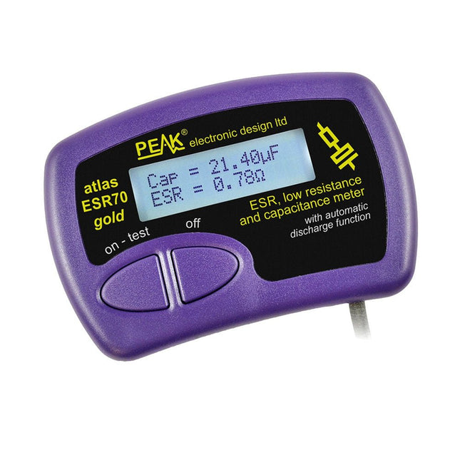
Peak Peak Atlas ESR70 gold (ESR- en capaciteitsmeter)
The Peak Atlas ESR70 gold is an enhanced version of the previous Peak Atlas ESR70 Plus. It does everything that the ESR70 Plus did but better. It now measures capacitance up to 10x faster, and over a wider range, thanks to new test algorithms. The capacitance measurement is also much less influenced by parallel resistances or leakage current thanks to our new Triple-Slope measurement system. Using the supplied gold plated probes (removable), the Atlas ESR70 gold can measure ESR down to a resolution of 0.01 ohms, up to 40 ohms. It can even measure ESR for capacitors that are in-circuit. Probes are removable, allowing 2 mm compatible probes to be fitted. Audible alerts are produced for various ESR levels allowing you to perform many tests in succession without having to look at the display. The ESR70 automatically takes capacitive reactance into account, so even low value capacitors (down to 0.3 uF) can have the ESR measured accurately. Kenmerken Uses a single AAA Alkaline cell (included). Alphanumeric LCD with backlight. Automatic analysis-start when you apply the probes. Automatic capacitor discharge using controlled discharge function. ESR (and low DC resistance) measurement (even in-circuit). Capacitive reactance automatically taken into account to ensure accurate ESR. Capacitance measurement (if testing out-of-circuit). Audible alerts for various ESR levels. Extended ESR measurement range up to 40 Ohms. Optional probe alternatives easily fitted. New gold Features Improved LCD with better backlight. 10x faster capacitance measurement for large capacitors. Enhanced user options system. New triple-slope measurement system to vastly reduce the influence of parallel resistance and/or leakage current on capacitance measurements. Much wider capacitance measurement range now 0.3 uF to 90,000 uF (was 1uF to 22,000uF). Specificaties Analyzer type ESR and Capacitance Component types Capacitors (>0.3 uF) ESR range 0.00 Ohms to 40.0 Ohms ESR resolution From 0.01 Ohms In-circuit use ESR only Capacitance range 0.3 uF to 90000 uF Battery type 1.5 V Alkaline AAA Cell (supplied). Life typically 1500 ops Display type Alphanumeric LCD (with backlight) Inbegrepen Peak Atlas ESR70 gold Extra-long and extra-flexible test cables (450 mm of Silicone covered cable) 2 mm gold plated plugs and sockets with removeable gold plated crocodile clips Comprehensive illustrated user guide AAA Alkaline cell Downloads Datasheet (EN) User Guide (EN)
€ 143,99
-

Great Scott Gadgets Great Scott Gadgets HackRF Pro SDR (100 kHz – 6 GHz) + GRATIS e-book
ACTIE: Bestel de HackRF Pro nu en ontvang het e-book "SDR with HackRF One & HackRF Pro" ter waarde van € 20 gratis! HackRF Pro is de nieuwste Software Defined Radio (SDR) van Great Scott Gadgets en de krachtige opvolger van de legendarische HackRF One. Met een frequentiebereik van 100 kHz tot 6 GHz bestrijkt het een enorm spectrum voor het verzenden en ontvangen van radiosignalen. Ontworpen als een open-source hardwareplatform, is de HackRF Pro de ideale tool voor het analyseren en ontwikkelen van moderne draadloze technologieën. Het kan flexibel worden gebruikt als USB-randapparaat of worden geprogrammeerd voor zelfstandig (standalone) gebruik. Specificaties Frequentie: 100 kHz tot 6 GHz Instelbaar van 0 Hz tot 7,1 GHz Half-duplex transceiver Tot 20 miljoen samples per seconde 8-bits kwadratuur-samples (8-bits I en 8-bits Q) Compatibel met GNU Radio, SDR# en meer Softwarematig configureerbare RX- en TX-versterking en basisbandfilter Softwarematig geregelde RF-poortvoeding (50 mA bij 3,3 V) SMA RF-connector SMA-klokingang en -uitgang voor synchronisatie en triggering Handige knoppen voor programmering Interne pinheaders voor uitbreiding High-Speed USB 2.0 met USB-C connector Voeding via USB Open source hardware In vergelijking met zijn voorganger, biedt HackRF Pro een aantal nieuwe functies, waaronder: Breder werkfrequentiebereik Verbeterde RF-prestaties met een vlakkere frequentierespons USB-C-connector Ingebouwde TCXO-kristaloscillator voor superieure timingstabiliteit Logica-upgrade van een CPLD naar een energiezuinige FPGA Eliminatie van de DC-piek Uitgebreide precisie-modus met 16-bits samples voor lage samplefrequenties (typische ENOB: 9-11) Halfprecisie-modus met 4-bits samples tot 40 Msps Meer RAM en flashgeheugen voor aangepaste firmware Afscherming rond het radiogedeelte Trigger-ingang en -uitgang toegankelijk via klokconnectoren Uitsparing in de printplaat biedt ruimte voor toekomstige uitbreidingen add-ons Verbeterd energiebeheer Verbeterde bescherming van de RF-poort Mogelijkheid om de zendmodus hardwarematig uit te schakelen Volledige compatibiliteit: Dankzij de beproefde architectuur kan bestaande software voor de HackRF One ook direct worden gebruikt met de HackRF Pro. De HackRF Pro biedt naadloze achterwaartse compatibiliteit en tegelijkertijd aanzienlijk verbeterde prestaties. Let op: Een antenne is niet inbegrepen. Wij raden de ANT500 aan voor een optimale start. Inbegrepen HackRF Pro SDR met kunststofbehuizing E-book: SDR with HackRF One & HackRF Pro (normale prijs: € 20) Downloads Documentation GitHub
€ 449,00€ 429,00Beste prijs
-

JOY-iT JOY-iT PS1440-C-Pro Programmeerbare Laborvoeding met RS485 (1440 W)
Met de JOY-iT PS1440-C-Pro krijgt u een programmeerbare laboratoriumvoeding die gelijkspanningen levert van 0,01 tot 60 V en gelijkstromen van 0,01 tot 24 A aan de spanningsuitgang. Met het intuïtieve bedieningspaneel kunt u tot 9 verschillende gelijkspanningsinstellingen programmeren, opslaan en oproepen. U kunt ook individuele beveiligings- en begrenzingsfuncties configureren, zoals overspanningsbeveiliging. Alle instellingen kunnen eenvoudig worden aangepast via het toetsenbord en/of de draaiknop en worden duidelijk weergegeven op het kleurendisplay met hoge resolutie van 2,4 inch. Voor verbeterde connectiviteit is de PS1440-C-Pro voorzien van een RS485-interface voor robuuste communicatie over lange afstanden. Dit maakt hem ideaal voor complexe opstellingen waar signaalstabiliteit, ruisimmuniteit en betrouwbare gegevensoverdracht cruciaal zijn. De meegeleverde connector zorgt voor een veilige verbinding, wat de algehele betrouwbaarheid en prestaties van uw laboratoriumapparatuur verbetert. Kenmerken Compleet apparaat klaar voor onmiddellijk gebruik RS485-interface Accu oplaadfunctie Waarden kunnen gemakkelijk worden ingevoerd via het toetsenbord Overstroom- en overspanningsbeveiliging instelbaar Geïntegreerde RTC, NTC-temperatuursensor Inclusief gedetailleerde documentatie in het Engels, Duits en Frans Specificaties Ingangsspanning 230 V Uitgangsspanning 0-60 V Uitgangsstroom 0-24 A Uitgangsvermogen 0-1440 W Nauwkeurigheid ingangsspanning ±1% + 5 cijfers Nauwkeurigheid uitgangsspanning ±0,3% + 3 cijfers Nauwkeurigheid uitgangsstroom ±0,5% + 5 cijfers Accuspanning ±0,5% + 3 cijfers Meetresolutie ingangsspanning 0,01 V Meetresolutie van uitgangsspanning 0,01 V Resolutie stroommeting 0,01 V Meetresolutie accuspanning 0,01 V Reactietijd in constante spanningsmodus 2 ms @ 0,1-5 A Belastingregeling in constante spanningsmodus ±0,1% + 2 cijfers Belastingregeling in constante stroommodus ±0,1% + 3 cijfers Meetbereik elektrische lading 0-9999,99 Ah Meetbereik energie 0-9999,99 Wh Statistische fouten in elektrische lading en energie ±2% Uitgangsrimpel 100 mV Vpp @ 12 V 150 mV Vpp @ 24 V Detectiebereik temperatuursensor ?10~+100°C Nauwkeurigheid temperatuurdetectie sensor ±3°C Werkmodus Trapsgewijze werking Instelling schermhelderheid Niveau 0-5, 6 niveaus in totaal Toegestane werktemperatuur −10~40°C Afmetingen 170 x 93 x 340 mm Inbegrepen JOY-iT PS1440-C Voeding 2-pins connector voor RS485-interface Netsnoer Manual Downloads Datasheet MODBUS Protocol PC Software Driver for Windows
€ 499,00
Leden: € 449,10
-

Elektor Zenerdiode-tester
De Elektor Zenerdiode-tester is in wezen een constante-stroombron die in stappen van 1 tot 50 mA kan worden geschakeld. Hij kan worden gebruikt om zenerdiodes tot een maximum van 54 V te testen. Dankzij een 60-V step-upconverter kan het apparaat worden gevoed met de gebruikelijke 5 tot 12 V. Het principe van deze tester is eenvoudig. Een zenerdiode of een ander DUT (device under test, zoals een LED) wordt gevoed door een instelbare stroombron. De spanning over het DUT kan met een multimeter worden gemeten. De spanning van de meeste (kleine) zenerdiodes wordt gespecificeerd bij een stroom van 5 mA. Afhankelijk van de toepassing kan ook de spanning bij andere stromen interessant zijn. Daarom zijn er zes stroominstellingen beschikbaar: 1, 2, 5, 10, 20 en 50 mA. LED’s worden vaak gespecificeerd bij een stroom van 20 mA. Wat kan worden getest: Of een zenerdiode defect is (kortsluiting of hoogohmig). Of een zenerdiode de juiste zenerspanning heeft. Hoe een zenerspanning verandert bij verschillende stromen. Welke exacte spanning aanwezig is bij een geïntegreerde spanningsreferentie. Of LED’s in een serieschakeling verschillen in helderheid (vandaar de stroom van 20 mA). Wat de stroomversterking is bij verschillende basisstromen in (vermogens)transistoren. De kit bevat alle onderdelen die in de stuklijst staan vermeld, inclusief printplaat en behuizing. Specificaties Voedingsspanning 5…12 V/2 A (USB-C) Voedingsstroom (Itest = 50 mA) 1,1 A bij 5 V / 412 mA bij 12 V Selecteerbare stromen 1, 2, 5, 10, 20 en 50 mA Max. testspanning >54 V bij Itest ≥1 mA Max. uitgangsspanning 60 V bij Itest = 0 mA Spanningslimiet bij 5 V 4,5 V bij Itest = 1 mA / 5,18 V bij Itest = 50 mA Afmetingen (behuizing) 110 x 82 x 44 mm Afmetingen (PCB) 105,4 x 67,3 mm Aansluitingen 4 mm banaanstekkerbussen voor multimeter 2 mm banaanstekkerbussen voor testklemmen USB-C-aansluiting voor voeding Inbegrepen Weerstanden R1 = 3.3 kΩ, 600 mW, 1% R2 = 0.15 Ω, 1 W, 5%, LS 12.7 mm, ø 3.5 mm R3, R8 = 180 Ω, 600 mW, 1% R4, R6, R16 = 1 kΩ, 600 mW, 1% R5, R19 = 47 kΩ, 600 mW, 1% R7 = 3.9 kΩ, 1 W, 5%, LS 12.7 mm, ø 3.5 mm R9, R10, R12 = 10 kΩ, 600 mW, 1% R11, R13 = 100 Ω, 600 mW 1% R14 = 249 Ω, 600 mW, 1% R15 = 499 Ω, 600 mW, 1% R17 = 2.49 kΩ, 250 mW, 1% R18 = 4.99 kΩ, 250 mW, 1% Condensatoren C1 = 470 uF / 35 V, 20%, Ir = 1.86 A, ø 12.5 mm, LS 5 mm, ESR = 0.038 Ω (Panasonic EEUTP1V471) C2 = 1 uF / 100 V, 10%, X7R, LS 5 mm C3 = 2.2 nF / 50 V, 10%, X7R, LS 5 mm C4, C7 = 100 nF / 100 V, 10%, X7R, LS 5 mm C5 = 100 uF / 100 V, 20%, ø 14 mm max., LS 5 mm C6 = 1 nF / 100 V, 10%, X7R, LS 5 mm Inductor L1 = 100 uH, Irms = 2.4 A, Isat = 3.5 A, 0.09 Ω, radial, pitch 2.5/5/10 mm, ø 14 mm max. (Kemet SBC8-101-242) Halfgeleiders D1 = MUR120G, DO-41 D2, D4 = STPS3150RL, DO-201AD D3 = Z-diode, 18 V, 1.3 W (BZX85C18) D5 = Z-diode, 5.1 V, 0.5 W (1N5231B) LED1 = LED in pushbutton S1 LED2 = LED, green, 3 mm IC1 = MC34063, DIP-8 IC2 = LM4040BIZ-5.0/NOPB, TO-92 (TO-226AA-3) IC3 = TL051CP, DIP-8 T1 = BC327.25, TO-92 T2 = STP40NF10L, TO-220 T3 = IRF9510PBF, TO-220 T4 = 2N7000, TO-92 Overige K1, K2, S1, S3 = 2-way screw terminal block, LS 3.5 mm, max. 1.5 mm² connected to K1 = USB-C socket, 30 V/3 A, chassis mounted, wired, 9 x 16 mm connected to K2 = Banana Connector, 2 mm, Socket, 60 VDC, Panel Mount, red (Multicomp 24.102.1) connected to K2 = Banana Connector, 2 mm, Socket, 60 VDC, Panel Mount, black (Multicomp 24.102.2) Test clip, red, 30 VAC/60 VDC (Hirschmann 931467101) Test clip, black, 30 VAC/60 VDC (Hirschmann 931467100) S1 = Pushbutton, panel mount, SPST-NO, 30 DC/100 mA, with red LED S2 = Rotary Switch, 6 position, 2 pole, 30°, 250 V/150 mA S3 = Toggle switch, panel mount, SPDT, solder lugs, 28 VDC T2, T3 = Heat sink, 15°C/W, FK 214 SA-CB Enclosure Hammond 1591XXSSBK, ABS, 110 x 82 x 44 mm Knob for S2, round shaft 6 mm, ø 21 mm, with indicator line (Multicomp CP-LB21-6-6D) 4 x Self-tapping screw #4-1/4", carbon steel, pan head Banana plug, red, 2 mm, 60 VDC (Multicomp 25.205.1) Banana plug, black, 2 mm, 60 VDC (Multicomp 25.205.2) Banana socket, black 4 mm, panel mount Banana socket, red 4 mm, panel mount for LED1, LED2 = Pin header, 1 x 2, vertical, pitch 2.54 mm for LED1, LED2 = Pin socket, 1 x 2, vertical, pitch 2.54 mm for T2, T3 = M3 screw, 10 mm, steel, pan head 2 x M3 washer, plain, steel 4 x M3 nut for IC1, IC3 = DIP-8 socket Wire, black, 0.25 mm² (24 AWG), stranded 14 x 0.15 mm, 1 m Wire, red, 0.25 mm² (24 AWG), stranded 14 x 0.15 mm, 1 m PCB 250772-1 v1.1 Links Artikel Elektor Labs
€ 79,95
Beste prijs
-

FNIRSI FNIRSI SWM-20 Dubbelpuls-puntlasapparaat
De FNIRSI SWM-20 handlasmachine is een zeer efficiënt, gebruiksvriendelijk en gemakkelijk mee te nemen lasapparaat. Hij is voorzien van dual-pulse puntlastechnologie, wat zorgt voor stabielere en betrouwbaardere lassen, en beschikt bovendien over een handige powerbankfunctie. Uitgerust met een 2,4-inch HD-display biedt de SWM-20 een duidelijke en intuïtieve bediening. Met de draaiknop kunnen gebruikers parameters snel en nauwkeurig aanpassen, waardoor het eenvoudig is om de gewenste lasinstellingen te kiezen en de algehele gebruikerservaring te verbeteren. Kenmerken 2-in-1: Puntlasapparaat en 5000 mAh powerbank 1200 A hoog vermogen voor sterke, betrouwbare lassen Dual-Pulse technologie voor schoner en stabieler lassen Twee A-klasse accu's met 8 veiligheidsfuncties Lasmogelijkheid voor meerdere materialen van 0,1–0,5 mm Meer dan 10.000 precisie-instelniveaus voor professionele controle 2,4-inch TFT-display met realtime gegevensbewaking Specificaties Maximale lasstroom 1200 A Batterijcapaciteit 5000 mAh Opladen 5 V/2,1 A Ontladen 5 V/2,1 A Lasmaterialen Nikkel, ijzer, roestvrij staal Lasdikte 0,1-0,5 mm Niveau 4 vooraf ingestelde combinaties Niveaus Inbegrepen 1x FNIRSI SWM-20 puntlasapparaat 2x Laspennen 2x Vervangingstips 1x Nikkelstrip 1x USB-C kabel 1x Manual Downloads Manual
€ 67,95
Beste prijs
-
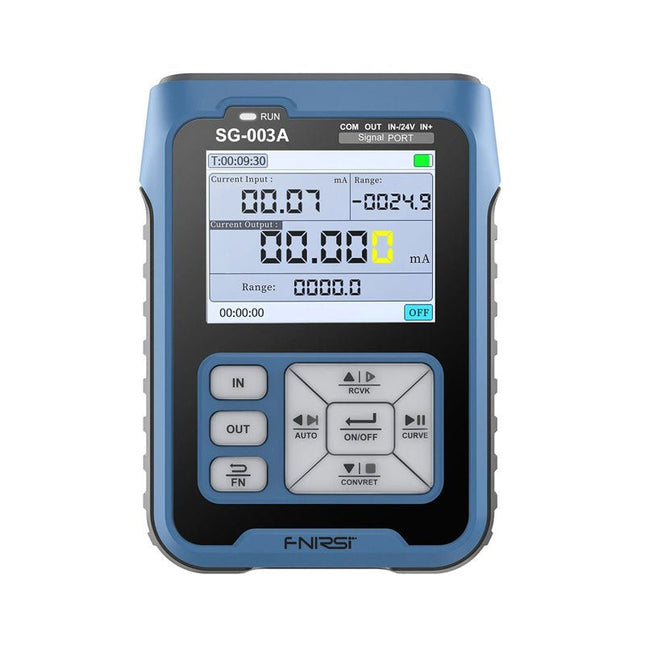
FNIRSI FNIRSI SG-003A Signaalgenerator
De FNIRSI SG-003A multifunctionele signaalgenerator, ook bekend als procesmeter/kalibrator, is een zeer nauwkeurige spanning-/stroomgenerator en -meter. De SG-003A levert zeer nauwkeurige referentiespanningen of -stromen voor het testen en kalibreren van andere meetinstrumenten, zoals multimeters en oscilloscopen. Naast spanningen en stromen genereert de SG-003A ook rechthoekige puls signalen met nauwkeurig programmeerbare frequenties en inschakelduur. De convertor modus verandert de SG-003A in een nauwkeurige spanning gestuurde stroombron, of stroom gestuurde spanningsbron, en zelfs in een spanning- of stroom gestuurde frequentiegenerator. De SG-003A is een zeer handig hulpmiddel voor het controleren van de nauwkeurigheid en precisie van uw multimeter, en voor het testen van bijvoorbeeld LED's. Kenmerken Nauwkeurigheid (spanning/stroom) 0,1% ± 0,005 Resolutie (huidig) 0,01 mA Frequentie 0-10 kHz Resolutie 5 cijfers Uitgangsspanning 24 V Scherm 2,4" TFT LCD-scherm (320 x 240) Afmetingen 92 x 72 x 30 mm Gewicht 165 g Specificaties Signaal Bereik Precisie Resolutie Max belasting Externe voeding Actieve stroomuitgang 0~24 mA ±(0,1% + 0,005) 0,01 mA 750 Ω Passieve stroomuitgang (XMT) 0~24 mA ±(0,1% + 0,005) 0,01 mA 0~30 V Uitgangsspanning 0~24 V ±(0,1% + 0,005) 0,01 V 24 V loop 0~24 mA ±(0,1% + 0,005) 0,01 mA Frequentie uitgang 0~9999 Hz ±2% 5 cijfers Stroom ingang 0~24 mA ±(0,1% + 0,005) 0,01 mA Spanning ingang 0~3 0V ±(0,1% + 0,005) 0,01 V Inbegrepen 1x FNIRSI SG-003A signaalgenerator 4x Testclips 1x USB oplader 1x USB-C kabel 1x Handleiding Downloads Manual Firmware V4.3
€ 69,95
-

Elektor Labs Elektor Low-noise Labvoeding
De low-noise labvoeding van Elektor is een volledig analoge, instelbare, symmetrische unit met gemiddeld vermogen, zonder schakelende of digitale componenten. De uitgangsspanning is instelbaar tussen 0 V en ±22 V, en de uitgangsstroom kan worden ingesteld van 0 A tot 1 A. Doordat elke vorm van schakeltechniek wordt vermeden, levert het ontwerp extreem weinig ruis. Voor de weergave van beide uitgangsspanningen en -stromen worden vier kleine analoge paneelmeters met draaispoel gebruikt. De meeste moderne laboratoriumvoedingen en AC-adapters maken gebruik van schakelende technieken. Zelfs de beste uitvoeringen vertonen onvermijdelijk hoogfrequente rimpel en andere schakelartefacten op hun uitgang, die het testen van gevoelige analoge schakelingen kunnen verstoren en metingen van kleine signalen kunnen beïnvloeden. Om dit te voorkomen, is het concept hier een volledig analoge voeding. Hoewel deze minder efficiënt is dan vergelijkbare schakelende voedingen, is de lagere efficiëntie bij gebruik op de testbank nauwelijks van belang en zorgt deze voor schonere en betrouwbaardere meetresultaten. Omdat veel analoge schakelingen een symmetrische voeding vereisen, levert dit ontwerp positieve en negatieve uitgangsspanningen van gelijke grootte. Een kleine hoeveelheid afregeling is beschikbaar om eventuele onbalans te compenseren. Uiteraard is ook een instelbare stroombegrenzing aanwezig. De kit bevat de onderdelen die nodig zijn om de voeding te bouwen, met uitzondering van de transformatoren. Specificaties Uitgangsspanning 0…+22 V, 0, −22 V Uitgangsstroom 0…+1 A, 0…−1 A Ruis −85 dBV (bij 0,95 A/20 V, B = 22 kHz) −84 dBV (bij 0,95 A/20 V, B > 500 kHz) Rimpelspanning 50 µVRMS (bij 950 mA/20 V, B = 22 kHz, voornamelijk 100-Hz-component) Inbegrepen 3x printplaten: regelaar (PCB-1), netfilter (PCB-2) en transformator (PCB-3) Alle componenten, behalve de AC-transformatoren 4x draaispoelmeters Extra onderdelen voor de bedrading (draden, banaanstekkerbussen, IEC-voedingsmodule, enz.) Niet inbegrepen De drie AC-transformatoren Een behuizing Onderdelenlijst Voor de regelaar-printplaat (240386-1) Weerstanden (250 mW, 1%) R1 = 12 Ω R2, R8, R37, R62 = 1 MΩ R3, R7, R10, R13, R17, R20, R22, R30, R35, R42, R45, R47, R55, R60 = 100 Ω, 600 mW R4, R5 = 4.7 kΩ R6 = 100 kΩ R9, R12, R14, R36, R38, R39, R61, R63, R66, R72, R78, R79 = 10.0 kΩ, 600 mW R11 = 9.76 kΩ, 600 mW R15, R40 = 44.2 kΩ, 600 mW R16, R41, R77 = 1 kΩ R18, R43 = 1.5 kΩ, 1 W, 5% R19, R44 = 470 Ω, 1 W, 5% R21, R46 = 330 Ω, 600 mW R23, R24, R48, R49 = 1.0 Ω, 1 W R25, R50 = 1 kΩ, 1 W, 5% R26, R28, R51, R53 = 1.000 kΩ 0.1%, 15 ppm/C R27, R29, R52, R54 = 10.00 kΩ 0.1%, 15 ppm/C R31, R56 = 1.2 kΩ, 1 W, 5% R32, R57 = 47 kΩ R33, R58 = 270 Ω R34, R59 = 27 kΩ R64, R69 = 12.0 kΩ R65 = 3.0 kΩ, 600 mW R67, R80 = 470 Ω, 600 mW R68, R70 = 6.8 kΩ, 600 mW R71 = 30.0 kΩ,, 600 mW R73, R74, R75, R76 = 10 MΩ P1, P2, P3 = 10 kΩ, 200 mW, 20%, potentiometer, 1 turns, single, lin., panel mount P4, P5 = 500 Ω, 500 mW, 10%, trimmer, 25 turns, 3296Y-1-501LF Bourns P6, P7 = 10 kΩ, 500 mW, 10%, trimmer, 25 turns, 3296Y-1-501LF Bourns Condensatoren C1 = 100 nF, 50 V, 10%, ceramic X7R, LS 5 mm C2, C3, C6, C7, C30 = 10 µF, 63V, 20%, LS 2.5 mm, 3000hours@105°C C4, C5, C8, C9, C13, C14, C18, C19, C23, C24, C28, C29, C31, C32, C38, C39 = 100 nF, 250 V, 10%, PET, LS 7.5 mm C10, C20 = 47 nF, 100 V, 5%, PET, LS 5 mm C11, C21 = 10 nF, 100 V, 5%, PET, LS 5 mm C12, C22 = 220 µF, 35 V, 20%, 0.024 Ω, LS2.5/3.5 mm, Ir 3.4 A, 2000hours@125°C, polymer C15, C25 = 120 µF, 50 V, 20%, ESR 0.02 Ω, Diam. 10 mm max., LS 5 mm C16, C26 = 15 nF, 100 V, 5%, PET, LS 5 mm C17, C27 = 47 nF, 100 V, 5%, PET, LS 5 mm C33, C34 = 22 µF, 50 V, 20%, LS 2 mm, 10000 hours @ 105°C C35, C36, C44, C45 = 1 µF, 100 V, 10%, LS 5 mm, ceramic X7R C37 = 100 uF, 50 V, 20%. LS 3.5 mm C40, C41, C42, C43, C46, C47, C48, C49 = 1000 µF, 50 V, 20%, LS 5/7.5 mm, Ir 3.32 A, 10000hours@105°C, D 16 mm C50, C51, C52, C53 = 47 nF, 100 V, 10%, ceramic X7R, LS 5 mm Spoelen L1, L2 = 4.7 µH, 3.2 A, 0.033 Ω, LS 5 mm, RLB0914-4R7ML Bourns L3 = Commom mode choke, 14.5 mH, 3 A, SSRH24NH-30145 Kemet Halfgeleiders D1, D2, D3, D4, D5, D9, D10, D11, D15 = BAT85, DO-34 D6, D7, D12, D13 = SR560, DO-201AD D8, D14, D16 = 1N4148, DO-35 D17 = Zenerdiode, 5.6 V, 0.5 W, DO-41 D18, D19 = 1N4004, DO-41 D20, D21 D22, D23 = V30100CI-M3/P, dual common cathode, TO-220 D24 = Zener diode, 30 V, 1 W, DO-41 LED1, LED2 = LED, red, T-1 (3 mm) LED3, LED4 = LED, green, T-1 (3 mm) TVS1, TVS2 = BZW50-33B, R6 T1, T2, T4 = BC337.25, TO-92 T3 = NJW0302G, TO-3P T5, T6, T8 = BC327.25, TO-92 T7 = NJW0281G, TO-3P T9 = BD139, TO-126 (SOT-32) IC1 = LM334Z, TO-92 IC2 = LM4040AIZ-5.0/NOPB, TO-92 (TO-226AA-3) IC3, IC4 = OPA2992IDR, SOIC-8 IC5, IC6 = OPA4992IDR, SOIC-14 IC7 = OPA992IDBVR, SOT-23-5 IC8 = LM339N, DIP-14 IC9 = LM317, TO-220 IC10 = LM337, TO-220 Overige F1, F2 = 5×20 mm fuse, 1.6 A, fast acting HS1, HS2 = Heatsink MC33271 (for T3/T7), 2.7°C/W, PCB mount, height 63.5 mm K1, K4 = 3-way screw terminal block, LS 3.5 mm, max. 1.5 mm² K2, K3 = 3-way screw terminal block, LS 3.5 mm, max. 1 mm² M1, M3 = Moving coil meter, Range 30 V, type 91C4, 45×45 mm M2, M4 = Moving coil meter, Range 1 A, type 91C4, 45×45 mm² RE1 = Relay DPDT,5V, UA2-5NU Diversen 3× 3-way screw terminal block, LS 3.5 mm, max. 1 mm² (for P1, P2, P3) 4× Pin header, 1×2, vertical, pitch 2.54 mm (for LED1, LED2, LED3, LED4) 4× Pin socket, 1×2, vertical. pitch 2.54 mm (for LED1, LED2, LED3, LED4) 2× Heatsink FK222SA220, 20°C/W, PCB mount (for IC9 & IC10) 2× Mica thermal pad for TO-220, 12×18×0.05 mm (for IC9 & IC10) 2× Insulating bushing IB 6, TO-220 (for IC9 & IC10) 2× Ceramic thermal pad, 23×20×2 mm (for T3 & T7) 2× PCB Fuse Holder, for 5×20 mm fuse, 10 A (for F1, F2) 2× Cover for PCB Fuse Holder, transparent (for F1, F2) 2× 2-way screw terminal block, LS 3.5 mm, max. 1 mm² (for M1 & M3) 2× 2-way screw terminal block, LS 3.5 mm, max. 1.5 mm² (for M2 & M4) 8× M3 solder lug, thickness 0.35 mm (for M1…M4) M4 solder lug, thickness 0.35 mm (to connect 4 mm banana connectors) Screened cable, 1 pair, 2×24 AWG/0.22 mm², 1 m (for P1, P2 & P3) IC socket, DIP, 14 contacts (for IC8) M3 washer, plain, steel M3 screw, 16 mm, steel, pan head M3 nut M3 spring washer 50 mm M3 standoff, steel, male-female 12 mm M3 standoff, steel, male-female 10 mm M3 standoff, steel, male-female M3 screw, 8 mm, steel, pan head Voor de netfilter-printplaat (240386-2) Weerstand R1 = 220 kΩ, 1 W, 500 V, 5% Condensatoren C1, C2 = 470 nF, 305 VAC, Class X2, 11 × 27 mm max., LS 15/22.5 mm C3, C4, C5, C6 = 2.2 nF, 300 VAC, Class Y2, 13 × 4 mm, LS 10 mm, PP Spoelen L1, L2 = Common-mode choke, 6.8 mH, 1.7 A, TDK B82732R2172B030 Halfgeleider MOV1 = TVS varistor, 300 VAC, S14K300 (230 VAC, B72214S0301K101) and SK14K150 (150 VAC, B72214S0151K101) Overige K1, K2 = 3-way screw terminal block, LS 7.62 mm F1 = Time-delay fuse, 0.5 A (230 VAC) or 1 A (115 VAC) Diversen 1× Fuse holder, 5×20 mm, 10 A, 500 VAC 1× Transparent fuse cover 4× 10 mm M3 standoff, steel, male–female 4× M3 screw, 8 mm, steel, pan head 4× M3 nut Voor de transformator-printplaat (240386-3) Weerstanden R1, R2 = 2.7 kΩ, 600 mW, 1% R3 = 10.0 kΩ, 600 mW, 1% Condensator C1 = 220 µF, 50 V, 20%, Ø10 mm, LS 5 mm, 4000 h @ 105°C Transformatoren (niet inbegrepen in deze kit!) TR1, TR2, TR3 = 2×7 V, 25 VA, PCB-mounted toroid, 70060K Talema Halfgeleiders D1–D4 = 1N4148, DO-35 D5, D6 = 1N4004, DO-41 D7 = Zener 5.6 V, 1.3 W, DO-41 LED1 = LED, red, T-1 (3 mm) IC1, IC2 = MOC8021M, CTR ≥ 1000%, DIP-6 Overige F1, F2, F3 = 160 mA time-delay fuse (230 VAC) or 315 mA time-delay fuse (115 VAC) K1 = 2-way screw terminal block, LS 7.62 mm K2 = 3-way screw terminal block, LS 3.5 mm, max 1.5 mm² K3, K4 = 3-way screw terminal block, LS 3.5 mm, max 1 mm² RE1, RE2 = Relay DPDT, 5 A/250 VAC / 24 VDC Diversen 1× Pin header 1×2, pitch 2.54 mm + matching socket for LED1 3× Fuse holder 5 × 20 mm, 10 A, 500 VAC + transparent cover 3× M4 screw, 8 mm, pan head + washer for TR1-TR3 8× M3 screw, 8 mm, pan head + nut + washer 8× 10 mm M3 standoff, steel, male–female 2× IC socket, DIP-6 for IC1 & IC2 Extra onderdelen 1 m red insulated wire, stranded, 1.5 mm² 0.5 m blue insulated wire, stranded, 1.5 mm² 0.5 m black insulated wire, stranded, 1.5 mm², 0.5 m 2 m red insulated wire, stranded, D 0.56 mm (0.25 mm²) 2 m black insulated wire, stranded, D 0.56 mm (0.25 mm²) 0.5 m Multicore Cable, Flexible, 3 Core, 0.75 mm² (24 x 0.2 mm) Red banana socket Black banana socket Blue banana socket Green banana socket IEC Power Entry Module with switch, IEC C14 3 crimp terminals, FASTON, 4.75 x 0.81 mm 3 knobs Links Elektor Labs JumpStarter Page Artikel (deel 1) Artikel (deel 2)
€ 249,00
Beste prijs
-

Elektor Publishing Professional SMD Assembly
Practical Low-Cost Methods for Reliable PCB Production This book explains how to carry out reliable SMD assembly using affordable tools and small-scale equipment. It follows the complete workflow step by step, including tool selection, solder paste handling, stencil use, component placement, reflow methods, inspection, and rework. The focus is on bench-level and small-lab production rather than industrial assembly lines. It shows practical methods for building single and double-sided SMD boards with repeatable results. Topics include solder paste and flux, temperature profiles, hot air and hotplate techniques, small reflow ovens, inspection methods, and defect correction. Checklists and example workflows are included to help reduce errors and improve consistency. Key features: Tools and supplies for SMD assembly and rework Solder paste types, storage, and handling Stencils and paste application methods Pick and place workflow and component orientation Temperature profiles and reflow methods Hot air, hotplate, and reflow oven processes Inspection and quality control Common defects such as tombstoning and solder bridges Practical rework and component replacement Bench-level professional workflows and checklists This book is designed as a practical bench reference for anyone who wants to assemble and troubleshoot their own SMD boards with reliable results.
€ 24,95
Leden: € 22,46
-

Elektor Digital Home Automation Projects with Arduino (E-book)
Using the RFID Starter Kit An Arduino board has now become ‘the’ basic component in the maker community. No longer is an introduction to the world of microcontrollers the preserve of the expert. When it comes to expanding the capabilities of the basic Arduino board however, the developer is still largely on his own. If you really want to build some innovative projects it’s often necessary to get down to component level. This can present many beginners with major problems. That is exactly where this book begins. This book explains how a wide variety of practical projects can be built using items supplied in a single kit together with the Arduino board. This kit, called the 'RFID Starter Kit for Arduino' (SKU 17240) is not just limited to RFID applications but contains more than 30 components, devices and modules covering all areas of modern electronics. In addition to more simple components such as LEDs and resistors there are also complex and sophisticated modules that employ the latest technology such as: A humidity sensor A multicolor LED A large LED matrix with 64 points of light A 4-character 7-segment LED display An infra red remote-controller unit A complete LC-display module A servo A stepper motor and controller module A complete RFID reader module and security tag On top of that you will get to build precise digital thermometers, hygrometers, exposure meters and various alarm systems. There are also practical devices and applications such as a fully automatic rain sensor, a sound-controlled remote control system, a multifunctional weather station and so much more. All of the projects described can be built using the components supplied in the Elektor kit.
€ 29,95
Leden: € 26,96
-

Elektor Digital LEDs, Lasers, and Sunlight (E-book)
Principles, Design, and Real-World Applications of Modern Photonics Light shapes our world—from the glow of a simple LED to the precision of a laser beam and the immense power of the sun. LEDs, Lasers, and Sunlight – Principles, Design, and Real-World Applications of Modern Photonics is your comprehensive guide to understanding, designing, and applying modern light technologies. This book takes you on a journey from the fundamentals of photonics—covering the nature of light, optical laws, and color theory—to real-world engineering with today’s most important light sources. You’ll explore how LEDs work, how to design efficient lighting systems, and how to tackle practical challenges such as thermal management, power supply design, and optical performance. Beyond illumination, the book opens doors to specialized applications: horticultural lighting for plant growth, infrared and ultraviolet technologies, modern display systems from LCD to MicroLED, and the fascinating world of lasers—from their physics to their use in medicine, industry, and communication. It also connects light engineering to sustainability through solar energy and thermal radiation. Written with a strong practical focus, this book bridges theory and application. Whether you are an engineer, student, or advanced hobbyist, you’ll gain the tools to turn concepts into working solutions—from selecting components to building complete systems. If you want to understand light not just as a phenomenon, but as a powerful engineering tool, this book will illuminate the way.
€ 49,95
Leden: € 44,96
-

Elektor Digital Professional SMD Assembly (E-book)
Practical Low-Cost Methods for Reliable PCB Production This book explains how to carry out reliable SMD assembly using affordable tools and small-scale equipment. It follows the complete workflow step by step, including tool selection, solder paste handling, stencil use, component placement, reflow methods, inspection, and rework. The focus is on bench-level and small-lab production rather than industrial assembly lines. It shows practical methods for building single and double-sided SMD boards with repeatable results. Topics include solder paste and flux, temperature profiles, hot air and hotplate techniques, small reflow ovens, inspection methods, and defect correction. Checklists and example workflows are included to help reduce errors and improve consistency. Key features: Tools and supplies for SMD assembly and rework Solder paste types, storage, and handling Stencils and paste application methods Pick and place workflow and component orientation Temperature profiles and reflow methods Hot air, hotplate, and reflow oven processes Inspection and quality control Common defects such as tombstoning and solder bridges Practical rework and component replacement Bench-level professional workflows and checklists This book is designed as a practical bench reference for anyone who wants to assemble and troubleshoot their own SMD boards with reliable results.
€ 19,95
Leden: € 17,96
-

Elektor Classics The Ton Giesberts Collection (USB-stick)
Praktische projecten in analoge elektronica, audio en meer Ontdek een bijzondere verzameling van meer dan 250 elektronicaprojecten die in Elektor Magazine zijn gepubliceerd en zorgvuldig zijn geselecteerd door de gerenommeerde Elektor-labingenieur Ton Giesberts. De USB-stick brengt een grote verscheidenheid aan schakelingen, ontwerpen en praktische projectideeën samen die in de loop der jaren door talrijke Elektor-auteurs en engineers zijn ontwikkeld. Dit uitgebreide archief bestrijkt een breed scala aan elektronicatopics en vormt een waardevolle bron van kennis en inspiratie voor engineers, makers, studenten en elektronicahobbyisten. Meer dan 250 geselecteerde Elektor-projecten Zorgvuldig samengesteld door Elektor-engineer Ton Giesberts Ideaal om na te bouwen, te experimenteren en nieuwe ideeën te ontdekken Ontdek tientallen jaren Elektor-expertise in één uitgebreide projectcollectie. Highlights Q-Watt audioversterker Fortissimo-100 high-end versterker Buffer bord voor de Raspberry Pi 400 USB-naar-multiprotocol-serieelconverter DDS-functiegenerator AC/DC-vermogensmeter Charge-a-Phone Specificaties Geheugen 8 GB Connectoren 1x USB-A1x USB-C Systeemeisen Computer geschikt voor Adobe Reader vanaf versie 7 Webbrowser
€ 49,95
Leden: € 44,96


