
Zoekresultaten voor "esp3212 OR wi OR fi OR ble OR module"
-

Elektor Digital Elektor Mars/Avril 2023 (PDF)
Le chargeur intégré est disponible pour nos clients OR et VERT sur le site d'Elektor Magazine ! Pas encore membre ? Cliquez ici . Horloge 2.0 le réveil-matin de vos rêves PIO du RP2040 en pratique expérimentation des programmables E/S du RP2040 ChipTweaker du pauvre homme Nous avons des moyens (abordables) de vous faire parler générateur d'équipement externe avec interface USB deux PICs pour le prix d'un AVR vitamines audio pour micro ramollo Comment gonfler soi-même le levé de sortie d'un microphone FFT avec Maixduino Acquisition des spectres de fréquences sur le vif sans raison apparente pilote de moteurs pas à pas UCN5804 drôle de composant, la série simulation du circuit avec Micro-Cap Les premiers ministres transmettent un problème mondial Prix PAUL 2022 les jeunes talents de la technologie et des solutions créatives Mon première radio définie par logiciel réalisé, dans les 15 minutes la documentation des microcontrôleurs sans peine (1) la structure d'une fiche technique et pour l'IA et les systèmes d'embarquement ? outils, plaques et remplacement des éditeurs numériser une ferme verticale Infographie : embarqué et l'ia d'aujourd'hui et demain Présentation du TinyML Étude de cas KwickPOS Hautes performances pour tous Normes Ordinateur sur module démarrer en électronique Actifs des composants communication I²C avec Node.js et Raspberry Pi affiche des données de vos capteurs dans un navigateur sortie vidéo sur les microcontrôleurs (2) sorties VGA et DVI le système d'exploitation temps réel Metronom un RTOS pour les processeurs AVR DVI sur le RP2040 Entrées de Luke Wren, développeur compositeur avec Raspberry Pi L?afficher HAT Mini Aperçus d'affiches avec Raspberry Pi ! WEEF Awards 2022 : célébrez les bonnes choses Hexadoku
€ 10,95
-

Elektor Digital MIT App Inventor for AI and IoT (E-book)
Build Smart Applications with Raspberry Pi, Arduino, and ESP32 Discover how easy and exciting mobile app development can be with MIT App Inventor. This hands-on guide takes you from basic concepts to building real-world mobile applications using a simple visual programming approach—no prior coding experience required. You will create IoT and AI-powered apps for Android devices and explore how App Inventor can also be used with iPhones and iPads. Connect your applications to platforms such as Arduino UNO R4 WiFi, ESP32, Raspberry Pi Pico (2)W and Raspberry Pi 5, enabling you to build smart, connected systems. Inside the book, you will learn how to: Build interactive apps using buttons, images, sound, and multimedia Create text-to-speech and speech-recognition applications Develop camera-based and location-aware (GPS) apps Design useful tools such as calculators and educational apps Work with smartphone sensors like accelerometers and light sensors Build AI-powered applications, including voice assistants and image-generation features Send and receive messages, and create communication-based apps Connect mobile apps to hardware using Wi-Fi and Bluetooth Control real devices such as LEDs, motors, and sensors Designed for beginners, students, and hobbyists, this book focuses on learning by doing. By the end, you will have the skills and confidence to create your own innovative applications that interact with both the digital and physical worlds. Start building and turning your ideas into reality.
€ 34,95
Leden: € 31,46
-

Elektor Digital Elektor May/June 2023 (PDF)
Elektor GREEN and GOLD members can download their digital edition here. Not a member yet? Click here. Knowledge for All! Super Servo TesterTest Up to Four Servos Stand-Alone or In-System Analog Signals and MicrocontrollersADCs, DACs, Current Measurement, and More embedded world 2023 Sub-Nyquist Sampling in PracticeReliably Capturing Higher Frequencies Using Subsampling Android Smartphone Here, ESP32 There?Practical Pproject Using the Android Wi-Fi API Active 1-kHz Filter for Distortion MeasurementBetter Measurements Through Optimization of the Measurement Signal Starting Out in Electronics......Multivibrating Cheerfully Further! Err-lectronicsCorrections, Updates and Readers’ Letters The New I3C ProtocolA Worthy Successor to I²C, or Just More Hot Air? BlueRC: IR Remote Control with Smartphone and ESP32Adaptive and Universal Microcontroller Documentation Explained (Part 2)Registers and Block Diagrams Automating Test and MeasurementProgramming Test Equipment to Do What You Want Infographics: Test and Measurement Overvoltage Protection for Safe OperationTransient Protection for Non-Isolated DC/DC Power Modules Wiha Measuring EquipmentReliable Electrical Testers and Meters Automating Testing and Collaborating on Test Results From Life’s ExperienceHigh-Level Electronics Energy LoggerMeasuring and Recording Power Consumption Assembling the 4tronix M.A.R.S. Rover Kit Parking Disk with E-Paper DisplayAn Innovative Digital Replacement eCO₂ Telegram botAir-Quality Measurement with Telegram Notification Behind the Scenes of DIY High-End AudioElektor’s Ton Giesberts Interviewed on the Fine Art of Analog Design HomeLab ToursWork in Progress... RFID Tag Reading and RFID Door LockSample Projects from the Elektor Arduino Experimenting Bundle Oscilloscope Current Probe for RFRF Current Measurements Made Easy Not for the Faint-Hearted: Robot Arm KitWith Raspberry Pi Pico and MicroPython Generative AIWho Made This Anyway? Hexadoku
€ 7,50
-
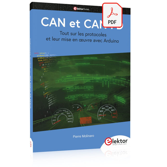
Elektor Digital CAN et CAN FD (E-book)
Tout sur les protocoles et leur mise en œuvre avec Arduino Initialement destiné aux véhicules routiers, le réseau CAN (« Controller Area Network ») et son successeur le réseau CAN FD (« Flexible Data ») ont vu leurs champs d’application s’élargir à de nouveaux domaines. L’industrie propose de nombreux modules microcontrôleurs dotés d’une interface CAN et/ou CAN FD. L’environnement de développement Arduino a démocratisé la programmation de ces modules et il existe des bibliothèques qui implémentent un pilote CAN et/ou un pilote CAN FD. La première partie dresse un rapide historique des réseaux CAN et CAN FD et expose la problématique des lignes de transmission en abordant succinctement leur théorie et présentant des résultats de simulation Spice. La deuxième partie est consacrée au réseau CAN, en détaillant successivement la fonction logique du réseau, les transcepteurs, les contrôleurs, la topologie la plus classique (le bus) et d’autres moins courantes, les répéteurs et les passerelles. Les aspects particuliers du protocole, tels que le bit stuffing, l’arbitrage, les trames d’erreur, la détection des erreurs sont exposés. La discussion de la fiabilité du protocole est illustrée par des exemples mettant en évidence ses faiblesses. La troisième partie présente le protocole CAN FD, ses deux variantes CAN FD ISO et CAN FD non ISO, leurs fiabilités, leurs faiblesses, mises en évidence par des exemples. Différents transcepteurs et contrôleurs CAN FD sont décrits. La quatrième partie est dédiée aux applications : comment utiliser les services d’un pilote, concevoir une messagerie, utiliser un analyseur logique. Deux exemples d’application terminent cette partie. Ce livre s’adresse aux amateurs et aux ingénieurs non spécialistes pour comprendre les possibilités qu’offre un réseau CAN et comment on le met en œuvre. Un enseignant trouvera des informations pour approfondir ses connaissances et pour concevoir des travaux pratiques. Une connaissance des microcontrôleurs, de leur programmation, de l’électronique numérique aidera à la lecture des schémas. La connaissance du langage C++ et du langage de simulation électronique Spice facilitera la compréhension des programmes qui sont décrits dans le livre. Tous les codes source sont disponibles sur le dépôt GitHub de l’auteur. Téléchargements GitHub
€ 34,95
Leden: € 31,46
-
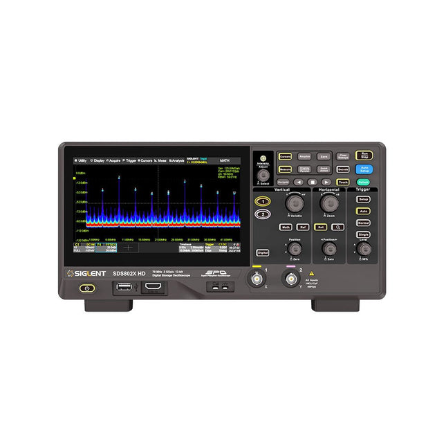
Siglent Siglent SDS822X HD 2-kanaals Oscilloscoop (200 MHz)
The Siglent SDS822X HD digital storage oscilloscope is based on 2 GSa/s, 12-bit Analog-Digital Converters and front ends with excellent noise floor performance. With a 200 MHz bandwidth, and a maximum record length of 100 Mpts, and the capability to analyze 2 analog channels alongside 16 digital channels, the SDS822X HD is perfectly suited for mixed signal analysis. Kenmerken 12-bit High Resolution 12-bit Analog-Digital Convertors with sample rate up to 2 GSa/s Front ends with 70 μVrms noise floor @ 200 MHz bandwidth 2/4 analog channels, up to 700 MHz bandwidth SPO technology Waveform capture rate up to 120,000 wfm/s (normal mode), and 500,000 wfm/s (sequence mode) Supports 256-level intensity grading and color temperature display modes. Up to 50 Mpts record length Digital trigger system Intelligent trigger: Edge, Slope, Pulse width, Window, Runt, Interval, Dropout, Pattern, Video (HDTV supported), Qualified, Nth edge, Delay, Setup/Hold time. Serial bus triggering and decoder, supports protocols I²C, SPI, UART, CAN, LIN. Segmented acquisition (Sequence) mode, dividing the maximum record length into multiple segments (up to 80,000), according to trigger conditions set by the user, with a very small dead time between segments to capture the qualifying event. History waveform record (History) function, the maximum recorded waveform length is 80,000 frames. Automatic measurements on 50+ parameters, supports statistics with histogram, track, trend, Gating measurement, and measurements on Math, History and Ref. 4 Math traces (2 Mpts FFT, addition, subtraction, multiplication, division, integration, differential, square root, etc.), supports formula editor. Abundant data analysis functions such as Search, Navigate, Counter, Bode plot and Power Analysis High Speed hardware-based Mask Test function, with Mask Editor tool for creating user-defined masks 16 digital channels (optional) 25 MHz waveform generator (optional) 7" TFT-LCD display with 1024 x 600 resolution; Capacitive touch screen supports multi-touch gestures. Interfaces include: USB Hosts, USB Device (USBTMC), LAN (VXI-11/Telnet/Socket), Pass/Fail, Trigger Out Built-in web server supports remote control over the LAN port using a web browser. Supports SCPI remote control commands. Supports external mouse and keyboard. Supports NTP. Specificaties Analog Channels 2 Bandwidth 200 MHz Vertical resolution 12-bit Sample rate (Max.) One channel mode: 100 Mpts/chTwo channel mode: Mpts/chFour channel mode: 25 Mpts/ch Memory depth (Max.) One channel mode: 50 Mpts/chTwo channel mode: 25 Mpts/ch Waveform capture rate (Max.) Normal mode: 120,000 wfm/sSequence mode: 500,000 wfm/s Trigger type Edge, Slope, Pulse width, Window, Runt, Interval, Dropout, Pattern, Video, Qualified, Nth edge, Delay, Setup/Hold time, Serial Serial trigger and decode (Standard) I²C, SPI, UART, CAN, LIN Measurement 50+ parameters, statistics, histogram, trend, and track supported Math 4 traces 2 Mpts FFT, Filter, +, -, x, ÷, ∫dt, d/dt, √, Identity, Negation, Absolute, Sign, ex, 10x, ln, lg, Interpolation, MaxHold, MinHold, ERES, Average. Supports formula editor Data analysis Search, Navigate, History, Mask Test, Counter, Bode plot, and Power Analysis Digital channel (optional) 16-channel; maximum sample rate up to 1 GSa/s; record length up to 10 Mpts USB AWG module (option) One channel, 25 MHz, sample rate of 125 MHz, wave length of 16 kpts, isolated output I/O 2x USB 2.0 Host, USB 2.0 Device, 10/100 M LAN, Auxiliary output (TRIG OUT, PASS/FAIL), SBUS (Siglent MSO) Probe (Standard) Passive probe PB470 for each channel Display 7 TFT-LCD with capacitive touch screen (1024x600) Inbegrepen 1x Siglent SDS822X Oscilloscope 2x Passive probe (200 MHz) PP520 1x Power cord (EU) 1x USB cable 1x Certificate of calibration 1x Quick start Downloads Datasheet Manual Programming guide
€ 635,25
-
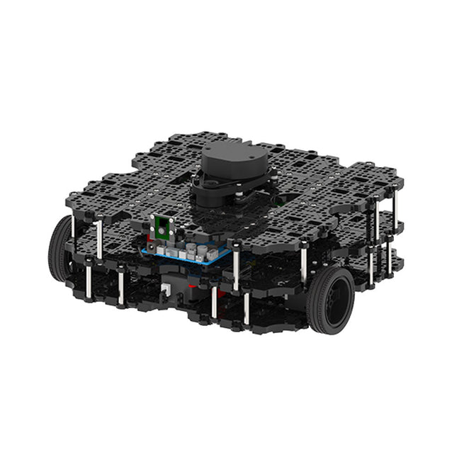
Robotis Robotis TurtleBot3 Waffle Pi (incl. Raspberry Pi 4)
World’s Most Popular ROS PlatformTurtleBot is the most popular open source robot for education and research. The new generation TurtleBot3 is a small, low cost, fully programmable, ROS based mobile robot. It is intended to be used for education, research, hobby and product prototyping.Affordable CostTurtleBot was developed to meet the cost-conscious needs of schools, laboratories and companies. TurtleBot3 is the most affordable robot among the SLAM-able mobile robots equipped with a 360° Laser Distance Sensor LDS-01.ROS StandardThe TurtleBot brand is managed by Open Robotics, which develops and maintains ROS. Nowadays, ROS has become the go-to platform for all the roboticists around the world. TurtleBot can be integrated with existing ROS-based robot components, but TurtleBot3 can be an affordable platform for whom want to get started learning ROS.ExtensibilityTurtleBot3 encourages users to customize its mechanical structure with some alternative options: open source embedded board (as a control board), computer and sensors. TurtleBot3 Waffle Pi is a two-wheeled differential drive type platform but it is able to be structurally and mechanically customized in many ways: Cars, Bikes, Trailers and so on. Extend your ideas beyond imagination with various SBC, sensors and motors on a scalable structure.Modular Actuator for Mobile RobotTurtleBot3 is able to get a precise spatial data by using 2 DYNAMIXEL’s in the wheel joints. DYNAMIXEL XM series can be operated by one of 6 operating modes (XL series: 4 operating modes): Velocity control mode for wheels, Torque control mode or Position control mode for joint, etc. DYNAMIXEL can be used even to make a mobile manipulator which is light but can be precisely controlled with velocity, torque and position control. DYNAMIXEL is a core component that makes TurtleBot3 perfect. It is easy to assemble, maintain, replace and reconfigure.Open Control Board for ROSThe control board is open-sourced in hardware wise and in software wise for ROS communication. The open source control board OpenCR1.0 is powerful enough to control not only DYNAMIXEL’s but also ROBOTIS sensors that are frequently being used for basic recognition tasks in cost effective way. Various sensors such as Touch sensor, Infrared sensor, Color sensor and a handful more are available. The OpenCR1.0 has an IMU sensor inside the board so that it can enhance precise control for countless applications. The board has 3.3 V, 5 V, 12 V power supplies to reinforce the available computer device lineups.Open SourceThe hardware, firmware and software of TurtleBot3 are open source which means that users are welcomed to download, modify and share source codes. All components of TurtleBot3 are manufactured with injection molded plastic to achieve low cost, however, the 3D CAD data is also available for 3D printing.Specifications Maximum translational velocity 0.26 m/s Maximum rotational velocity 1.82 rad/s (104.27 deg/s) Maximum payload 30 kg Size (L x W x H) 281 x 306 x 141 mm Weight (+ SBC + Battery + Sensors) 1.8 kg Threshold of climbing 10 mm or lower Expected operating time 2h Expected charging time 2h 30m SBC (Single Board Computers) Raspberry Pi 4 (2 GB RAM) MCU 32-bit ARM Cortex-M7 with FPU (216 MHz, 462 DMIPS) Remote Controller RC-100B + BT-410 Set (Bluetooth 4, BLE) Actuator XL430-W210 LDS (Laser Distance Sensor) 360 Laser Distance Sensor LDS-01 or LDS-02 Camera Raspberry Pi Camera Module v2.1 IMU Gyroscope 3 AxisAccelerometer 3 Axis Power connectors 3.3 V/800 mA5 V/4 A12 V/1 A Expansion pins GPIO 18 pinsArduino 32 pin Peripheral 3x UART, 1x CAN, 1x SPI, 1x I²C, 5x ADC, 4x 5-pin OLLO DYNAMIXEL ports 3x RS485, 3x TTL Audio Several programmable beep sequences Programmable LEDs 4x User LED Status LEDs 1x Board status LED1x Arduino LED1x Power LED Buttons and Switches 2x Push buttons, 1x Reset button, 2x Dip switch Battery Lithium polymer 11.1 V 1800 mAh / 19.98 Wh 5C PC connection USB Firmware upgrade via USB / via JTAG Power adapter (SMPS) Input: 100-240 VAC 50/60 Hz, 1.5 A @maxOutput: 12 VDC, 5 A Downloads ROS Robot Programming GitHub E-Manual Community
€ 1.879,00
Beste prijs
-

Holybro Holybro QAV 250 ARF Drone Kit
The QAV250 Kit is the perfect way to get started developing on either PX4 or Ardupilot. It pairs a carbon fiber 250 racing frame and essential electronics with Pixhawk 6C mini autopilot. The kit is easy to assemble. No soldering needed. Specifications Micro Power Module (PM06 v2) Motors: 2207 KV1950 Wheelbase: 250 mm Dimensions: 198 x 235 x 70 mm Weight: 347 g Included Carbon fiber 250 airframe with hardware Micro Power Module (PM06 v2) Motors: 2207 KV1950 5" Plastic Props Fully assembled Power Management Board with ESCs (BLHeli S ESC 20A) Battery Straps Note: LiPo battery is not included.
€ 214,95
Beste prijs
-

OWON OWON XDG2035 2-ch Arbitrary Waveform Generator (35 Mhz)
The 2-channel OWON XDG2035 is a function/waveform generator that can generate signals with a maximum frequency of 35 Hz. The generator has a resolution of 1 µHz and a sample rate of 500 MSa/s.The OWON XDG2035 is capable of generating 6 standard waveforms and 150 arbitrary waveforms. With the included software you can write advanced functions up to 10 million points. Waveforms can be saved to the function generator's internal memory using a PC via USB or LAN.The OWON XDG2035 also supports SCPI commands and LabView. The function generator has an integrated high-quality frequency counter, which can operate from 100 to 200 MHz.Features Max. 35 MHz frequency output 500 MSa/s Sample rate, Vertical resolution 1μHz 14 bits Vertical Resolution, 10 Marb waveform length Comprehensive waveform output: 6 basic waveforms,and 150 built-in arbitrary waveforms Comprehensive modulation functions: AM, FM, PM, FSK, 3FSK, 4FSK, PSK, OSK, ASK, BPSK, PWM, Sweep, and Burst High-accuracy frequency counter integrated, supported range 100-200 MHz SCPI and LabVIEW supported 7 inch multi-touch screen (800 x 480 pixels) Specifications Channel 2 Frequency Output 35 MHz Sample Rate 500 MSa/s Vertical Resolution 14 bits Waveform Standard Waveform sine, square, pulse, ramp, noise, and harmonic Arbitrary Waveform exponential rise, exponential fall, sin(x)/x, step wave, and others, total 150 built-in waveforms, and user-defined arbitrary waveform Frequency (resolution 1 μHz) Sine 1 μHz-100 MHz Square 1 μHz ~ 30 MHz Pulse 1 μHz ~ 25 MHz Ramp 1 μHz ~ 3 MHz Noise (-3 dB, typical) 100 MHz Arbitrary Waveform 1 μHz ~ 15 MHz Harmonic 1 μHz ~ 50 MHz Accuracy ±2ppm, 25°C ±5°C Waveform Length 2 points - 10M points Amplitude Into 50Ω load 1mVpp ~ 10Vpp (≤25 MHz); 1mVpp ~ 5Vpp (≤60 MHz); 1mVpp ~ 2.5Vpp (≤100 MHz) Modulation Type AM, DSB-AM, FM, PM, ASK, FSK, PSK, BPSK, QPSK, 3FSK, 4FSK, OSK, PWM, SUM Frequency Counter Function Frequency, period, +width, -width, +duty, and -duty Frequency Range 100 ~ 200 MHz Frequency Resolution 7 digits Input/Output Input mode frequency counter, external modulation input, external trigger input, internal clock output, external reference clock input/output Communication Interface USB Host, USB Device, LAN, RS232 (optional) Mechanical specifications Dimensions 340 x 177 x 90 mm Weight 2.3 kg Included 1x OWON XDG2035 1x Power Cord 1x CD-ROM 1x Quick start guide 1x USB Cable 1x BNC-BNC Cable DownloadsQuick Guide
€ 339,00
-

Elektor Digital Elektor AI Guest Edition 2024 (PDF) EN
Elektor GREEN and GOLD members can download their digital edition here. Not a member yet? Click here. The AlertAlfred AI Security SystemPowered by a Raspberry Pi 5 and the Hailo 8L Module AI in Electronics DevelopmentAn Update After Only One Year Intro to AI AlgorithmsPrompt: Which Algorithms Implement Each AI Tool? Single-Board Computers for Artificial Intelligence ProjectsBackground and Overview From Sensor Data to Machine Learning ModelsGesture Detection with an Accelerometer and Edge Impulse Build a Leaky Integrate-and-Fire Spiking NeuronArtificial Intelligence Without Software ChatGPT for Electronic DesignDoes GPT-4o Do It Any Better? Bringing AI to the Edge with ESP32-P4 Exploring Speech Functions on Raspberry Pi ZeroWhen Overclocking Gives Freedom of Speech The Growing Role of Edge AIA Trend Shaping the Future Unlocking the Power of Edge AIA Conversation with François de Rochebouët of STMicroelectronics A VHDL Clock Made with ChatGPT AI’s Real ImpactSayash Kapoor on “AI Snake Oil” and More The Latest Stuff From BeagleBoardBeagleY-AI, BeagleV-Fire, BeagleMod, BeaglePlay and BeagleConnect Freedom Mosquito Detection Using Open Datasets and Arduino Nicla Vision AI Today and Tomorrow: Insights from Espressif, Arduino, and SparkFun Artificial Intelligence Timeline BeagleY-AIThe Latest SBC for AI Applications AI in FocusPerspectives from the Elektor Community Machine Vision with OpenMVCreate a Soda Can Detector A Conversation with the Digital MindChatGPT vs Gemini Skilling Me Softly with This Bot?Is the AI Revolution in the Electronic Field Failing Due to a Lack of Social Precision?
€ 7,50
-
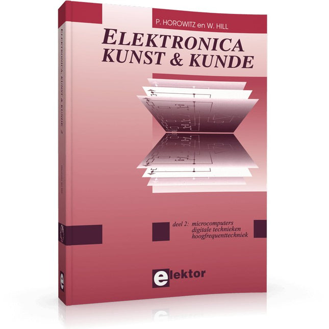
Elektor Publishing Elektronica Kunst & Kunde 2
In Elektronica Kunst & Kunde worden alle onderwerpen behandeld die ook in standaard elektronica-leerboeken aan de orde komen, plus een groot aantal belangrijke maar vaak veronachtzaamde zaken. In dit tweede deel aandacht voor onder meer de volgende onderwerpen: phase-locked loop-schakelingen, opto-elektronica, busschakelingen, capacitieve belasting, bekabeling, interfacing timing, naaldpulsen, klokvertraging, monostabiele multivibratoren de IBM-PC en de Intel-fanilie, RS232-kabels, seriële poorten, ASCII, modems, SCSI, IPI, GPIB, parallele poorten, local-area-networks de 68000-microprocessorfamilie, perifere LSI-chips, geheugen, programmeerbare instrumenten prototypering, het ontwerpen van printplaten, wire-wrap-technieken, CAD/CAM technieken, de bouw van schakelingen HF-modules, vereenvoudigd ontwerp van HF-versterkers en high-speed schakelaars batterijen, accu's en zonnecellen; micropower-regelaars, -opamps en -microprocessoren methoden om de bandbreedte te beperken, middeling van signalen, lock-in versterkers, pulshoogte-analyse, 'multichannel-scaling'
€ 39,95
Leden: € 35,96
-

Elektor Digital Elektor Special: Raspberry Pi und Pico (PDF)
Inhalt Projekte Pico-VoiceSprachverfremdung und Soundeffekte mit dem Raspberry Pi Pico Navi mit Vibrations-Feedback POV-Anzeige Impulsbreitenmodulation (PWM) mit dem Raspberry Pi Pico Verwendung von Wi-Fi mit dem Raspberry Pi Pico „Hello World“ vom Raspberry Pi Pico und RP2040Ein Blick auf den ersten Mikrocontroller der Raspberry Pi Foundation Einfacher Ein-Aus-Temperaturregler mit Raspberry-Pi-HAT Multitasking mit dem Raspberry PiBeispiel: Ampelsteuerung Das Raspberry-Pi-LinealSpaß mit einem Laufzeitsensor Puffer-Board für Raspberry Pi (Mk. 1)Nie wieder defekte I/O-Ports FM-Radio mit RDSEin HAT für den Raspberry Pi LoRa mit dem Raspberry Pi PicoViel Spaß mit MicroPython! Tutorials Qt für Raspberry Pi Raspberry Pi Pico Programmierungmit MicroPython und Thonny Raspberry Pi Full StackRPi und RF24 als Herzstück eines Sensornetzwerks Raspberry Pi – Bash-Befehle in der Übersicht Community Java auf dem Raspberry PiEin Interview mit Buch-Autor Frank Delporte Reviews Buchvorstellung: Raspberry Pi for Radio Amateurs Secure-Boot-Lösung für Raspberry PiViel Sicherheit zum vernünftigen Preis Review: SmartPi – Smartmeter-Erweiterung für Raspberry Pi Review: RPi-HAT Enviro+Umweltdaten messen mit Raspberry Pi und der HAT Enviro+ Review: Raspberry Pi 4Alles neu und doch gut? Schnelles 3,5“-Touch-Display für RPiMehr Leistung ohne Aufpreis
€ 11,90
Leden: € 10,71
-
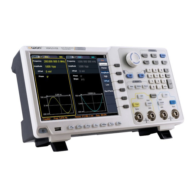
OWON OWON XDG3102 2-kanaals Arbitrary Waveform Generator (100 MHz)
Kenmerken Advanced DDS technology, up to 250MHz frequency output 1.25GS/s sampling rate, and 1 μHz frequency resolution Up to 1M arbitrary waveform length Vertical resolution: 14 bits Comprehensive waveform output: 6 groups waveforms, and 152 group built-in arbitrary waveforms Comprehensive modulation options: AM, FM, PM, FSK, 3FSK, 4FSK, PSK, OSK, ASK, BPSK, PWM, sweep, and burst High-accuracy frequency counter integrated, ranging from 100mHz till 200MHz SCPI and LabVIEW supported 8'' 800 x 600 pixels touch screen LCD Specificaties XDG3102 Channel 2 Frequency Output 100MHz Sample Rate 1.25GSa/s Vertical Resolution 14 bits Waveform Standard Waveform sine, square, pulse, ramp, noise, and harmonic Arbitrary Waveform exponential rise, exponential fall, sin(x)/x, step wave, and others, total of 150 built-in waveforms, and user-defined arbitrary waveform Frequency (resolution 1μHz) Sine 1μHz - 100MHz Square 1μHz - 40MHz Pulse 1μHz - 25MHz Ramp 1μHz - 5MHz Harmonic 1μHz - 50MHz Noise 120MHz (-3dB, typical) Arbitrary Waveform built-in waveform: 1uHz - 15MHzuser-defined waveform: 1uHz - 50MHz Accuracy ±1ppm, 0°C - 40°C Amplitude Amplitude (50Ω) 1mVpp - 10Vpp (≤40MHz); 1mVpp - 5Vpp (≤80MHz) 1mVpp - 2.5Vpp (≤120MHz); 1mVpp - 1Vpp (≤250MHz) Amplitude(high impedance) 2mVpp - 20Vpp (≤40MHz); 2mVpp - 10Vpp (≤80MHz); 2mVpp - 5Vpp (≤120MHz); 2mVpp - 2Vpp (≤250MHz) Resolution 1mV or 4 digits DC Offset Range (50Ω) ±(5 Vpk - Amplitude Vpp/2) Range (high-Z, open circuit) ±(10 Vpk - Amplitude Vpp/2) Accuracy ±(1% of |setting| + 1mV + Amplitude Vpp x 0.5%) Resolution 1mV or 4 digits Load Impedance 50Ω (typical) Accuracy ±(1% of setting + 1 mVpp) (typical, 1kHz sine, 0V offset) Sine Wave Spectrum Purity Harmonic Distortion Typical (0dB) DC - 1MHz: <-65dBc 1MHz - 10MHz: <-60dBc 10MHz - 120MHz: <-50dBc 120MHz - 200MHz: <-45dBc Total Harmonic Distortion ≤0.05 %, 10 Hz to 20 kHz, 1 Vpp Spurious (non-harmonic), Typical (0dB) ≤10MHz: <-70dBc >10MHz: <-70dBc + 6dB/ octave Phase Noise Typical (0 dBm, 10 kHz deviation) 10MHz: -110dBc/Hz Square Rise/Fall Time <5ns Overshoot <3% Duty Cycle 50.0% (fixed) Jitter (rms) 300ps + 100ppm Pulse Pulse Width 12ns - 996875s Leading/Trailing Edge Time ≤7ns Overshoot <3% Jitter (rms) 300ps + 100ppm Ramp Linearity ≤1% of peak output (typical, 1kHz, 1 Vpp, 50% symmetry) Symmetry 0% to 100% Harmonic Harmonic Order ≤16 Harmonic Type even, odd, all, user Harmonic Amplitude could be set for all the harmonics Harmonic Phase Arbitrary Waveform Length 2 points - 1M points Vertical Resolution 14 bits Minimum Rise/Fall Time <7ns Jitter (rms) 3ns Modulation Type AM, FM, PM, PWM, FSK, 3FSK, 4FSK, PSK, OSK, ASK, BPSK, sweep, and burst AM Carrier Waveform sine, square, ramp, and arbitrary (except DC) Source internal / external Modulating Waveform sine, square, ramp, noise, and arbitrary Depth 0.0% - 100.0% Modulating Frequency 2 mHz - 100 kHz FM Carrier Waveform sine, square, ramp, and arbitrary (except DC) Source internal / external Modulating Waveform sine, square, ramp, noise, and arbitrary Modulating Frequency 2 mHz - 100 kHz PM Carrier Waveform sine, square, ramp, and arbitrary (except DC) Source internal / external Modulating Waveform sine, square, ramp, noise, and arbitrary Phase Deviation 0° - 180° Modulating Frequency 2 mHz - 100 kHz PWM Carrier Waveform pulse Source internal / external Modulating Waveform sine, square, ramp, noise, and arbitrary Width Deviation 0 ~ minimum (pulse duty ratio, 100% - pulse duty ratio) Modulating Frequency 2 mHz - 100 kHz FSK / 3FSK / 4FSK Carrier Waveform sine, square, ramp, and arbitrary (except DC) Source internal / external Modulating Waveform square with 50% duty cycle Key Frequency 2 mHz - 1MHz PSK Carrier Waveform sine, square, ramp, and arbitrary (except DC) Source internal / external Modulating Waveform square with 50% duty cycle Key Frequency 2 mHz - 1MHz OSK Carrier Waveform sine, square, ramp, and arbitrary (except DC) Source internal Oscillation Time square with 50% duty cycle Key Frequency 2 mHz - 1MHz ASK Carrier Waveform sine, square, ramp, and arbitrary (except DC) Source internal / external Modulating Waveform square with 50% duty cycle Key Frequency 2 mHz - 1MHz BPSK Carrier Waveform sine, square, ramp, and arbitrary (except DC) Source internal Modulating Waveform square with 50% duty cycle Key Frequency 2 mHz - 1MHz Sweep Carrier Waveform sine, square, ramp, and arbitrary (except DC) Type linear, and log Direction up, and down Sweep Time 1 ms to 500s, ± 0.1% Trigger Source internal, external, and manual Burst Carrier Waveform sine, square, ramp, pulse, and arbitrary (except DC) Burst Count 1 to 50,000 period, infinite, gating Internal Period 10 ns - 500 s Gated Source external trigger Frequency Counter Function frequency period, +width, -width, +duty, and -duty Frequency Range 100mHz - 200MHz Frequency Resolution 7 digits Input / Output Display 8”800 x 600 pixels touch screen LCD Type frequency counter, external modulation input,external trigger input,external reference clock input / output Communication Interface USB Host, USB Device, and LAN Dimensions 340 x 177 x 90 mm Weight 2.50 kg
€ 650,00


