Learning circuit design the fun way
Welcome to the world of electronics!
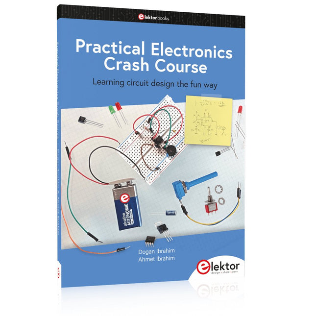
Getting started in electronics is not as difficult as you may think. Using this book, you will explore and learn the most important electrical and electronics engineering concepts in a fun way by doing various experiments and by simulating circuits. It will teach you electronics practically without getting into complex technical jargon and long calculations. As a result, you will be creating your own projects soon.
No prior knowledge of electronics is required, only some basic algebra is used in a few simple calculations. Many tested and working projects and simulations are presented to familiarise yourself with the construction of electronic circuits. Circuit simulation is introduced at an early stage to enable you to experiment with circuits easily without breaking anything.
You will learn:
The concepts of voltage, current, and power
AC and DC
Basic lamp circuits with switches
Passive components: resistors, capacitors & inductors
RC & RCL circuits
Electromagnetism
Loudspeakers, relays, buzzers, and transformers
Active components: diodes & LEDs, bipolar transistors & MOSFETs
Transistor-based switching circuits
Optocoupler circuits
Astable & monostable multivibrators
Using the 555 timer IC
The operational amplifier
Digital logic
Advanced examples: amplifiers, oscillators, filters, and sensors
Test and measurement tools
Microcontrollers: Arduino UNO, ESP32, Raspberry Pi Pico, and Raspberry Pi
Reading datasheets and best practices for selecting components
EMC & EMI and norms & regulations
Im vorliegenden Buch wird das weltweit verbreitete 0G-Netzwerk Sigfox zunächst detailliert vorgestellt. Danach wird auf der Basis eines leistungsfähigen Arduino-Sigfox-Boards eine universelle Sigfox-Test-, Mess- und Simulations-Plattform hardwaremäßig entwickelt und softwaremäßig betrieben. Diese Sigfox-Feldstation stellt dem Anwender eine Vielzahl von Möglichkeiten zur Verfügung: Sensoren, Aktoren und Displays inkl. GPS-Modul und Solargenerator.
Alle Schaltungsteile (inkl. den 3D-Plott-Vorlagen für ein passendes Stationsgehäuse) und sämtlichen Softwaremodule werden offen gelegt, so dass der Leser damit weitere Sigfox-Feldstationen nach seinen eigenen Vorstellungen und Bedürfnissen entwickeln und problemlos einsetzen kann.
Die Visualisierung, Auswertung und Speicherung der erfassten Felddaten wird anhand eines Freeware Dashboard Programms, mit Schnittstelle zu Google Maps, ausführlich beschrieben.
Themenauswahl:
Industrie 4.0, Internet of Things, 0G-Netzwerke
Das Sigfox-Netzwerk: Übertragungstechnik, Uplink/Downlink, das Monarch-Konzept, Geolokalisierung, Sigfox-Atlas-Konzept
Das Sigfox-Backend, die Callbacks und die REST-API
Aufbau der universellen Sigfox-Test-, Mess- und Simulations-Plattform auf der Basis des Arduino-Sigfox-Moduls MKR FOX1200
Die grundlegende Betriebssoftware für alle Komponenten
Die Arduino-Sigfox-Bibliothek und der Sigfox-Betrieb – Anmeldung bei der Sigfox-Cloud, Aussendung von Mess- und Zustandswerten
Die Sigfox-Callbacks – Der Datentransfer von der Sigfox-Cloud zum Anwender: E-Mails, Mess- und Zustandswerte, GeoLoc-Daten
Die individuelle Gestaltung von Anwender-Dashboards
Hardwareerweiterungen: HMI-Display, Thermoelementverstärker, Multichannel-Gassensor, Feinstaubsensor, GPS-Modul und vieles mehr
Kommerzielle Sigfox-Stationen
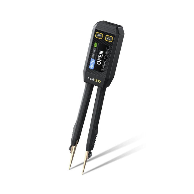
De FNIRSI LCR-ST1 is een compacte, multifunctionele en intelligente LCR-tester die automatische metingen van weerstand, capaciteit, inductantie, diodetests en continuïteit ondersteunt.
Het 1,14-inch kleurendisplay in combinatie met een handige magnetische adsorptiefunctie verbetert het gebruiksgemak, terwijl de ingebouwde lithiumbatterij van 250 mAh langdurige prestaties garandeert. Het apparaat ondersteunt drie frequentiebereiken (100 Hz, 1 kHz en 10 kHz) en biedt 0,3 V en 0,6 V RMS-testniveaus voor veelzijdige testtoepassingen.
Het unieke pincetvormige ontwerp van de LCR-ST1 is ideaal voor delicate taken in kleine ruimtes en maakt het snel en nauwkeurig testen van elektronische componenten mogelijk. Het lichte gewicht en het draagbare ontwerp maken het tot een hulpmiddel van onschatbare waarde voor zowel veld- als laboratoriumgebruik.
Of u nu een ervaren ingenieur bent of net begint in de elektronica, de LCR-ST1 levert betrouwbare en nauwkeurige meetresultaten, waardoor u uw taken efficiënter en nauwkeuriger kunt uitvoeren.
Kenmerken
Biedt 3 testfrequenties (100 Hz, 1 kHz, 10 kHz) en 2 testspanningsniveaus.
Beschikt over automatische componentidentificatie voor snellere en betrouwbaardere metingen.
1,14-inch kleurendisplay met hoge resolutie voor duidelijke aflezingen.
Ondersteunt automatische gegevensregistratie en -opslag.
De pincetpunten zijn gemaakt van verguld messing voor verbeterde duurzaamheid en geleiding.
Specificaties
Weerstandsbereik
10 mΩ – 10 MΩ
Capaciteitsbereik
1 pF – 22 mF
Inductiebereik
1 μu – 10 H
Diode
Aanspanning 0,7 V
Frequentietest
100 Hz, 1 kHz, 10 kHz
Niveautest
0,3 V, 0,6 V RMS
Parameterweergave
ESR, D-waarde, Q-waarde, Z-waarde, X-waarde
Display
1,14" HD-kleurenscherm
Oplaadinterface
USB-C, 5 V/1 A
Voeding
Ingebouwde lithiumbatterij van 250 mAh
Automatische herkenningsmeting
Ja
Vervangbare pincetkop
Ja
Automatische uitschakeling
Ja
Gegevensopslag
Ja
Geschiedenisrecord
Verbinden met pc om te bekijken en exporteren
Afmetingen
28 x 19 x 150 mm
Gewicht
41 g
Inbegrepen
1x LCR-ST1 SMD-pincet
2x Haakpunten
1x Magnetische patch
1x USB-kabel
1x Opbergtas
1x Manual
Downloads
Manual
Firmware V1.6
Practical Multitasking Fundamentals
Programming embedded systems is difficult because of resource constraints and limited debugging facilities. Why develop your own Real-Time Operating System (RTOS) as well as your application when the proven FreeRTOS software is freely available? Why not start with a validated foundation?
Every software developer knows that you must divide a difficult problem into smaller ones to conquer it. Using separate preemptive tasks and FreeRTOS communication mechanisms, a clean separation of functions is achieved within the entire application. This results in safe and maintainable designs.
Practicing engineers and students alike can use this book and the ESP32 Arduino environment to wade into FreeRTOS concepts at a comfortable pace. The well-organized text enables you to master each concept before starting the next chapter. Practical breadboard experiments and schematics are included to bring the lessons home. Experience is the best teacher.
Each chapter includes exercises to test your knowledge. The coverage of the FreeRTOS Application Programming Interface (API) is complete for the ESP32 Arduino environment. You can apply what you learn to other FreeRTOS environments, including Espressif’s ESP-IDF. The source code is available from GitHub. All of these resources put you in the driver’s seat when it is time to develop your next uber-cool ESP32 project.
What you will learn:
How preemptive scheduling works within FreeRTOS
The Arduino startup “loopTask”
Message queues
FreeRTOS timers and the IDLE task
The semaphore, mutex, and their differences
The mailbox and its application
Real-time task priorities and its effect
Interrupt interaction and use with FreeRTOS
Queue sets
Notifying tasks with events
Event groups
Critical sections
Task local storage
The gatekeeper task
De OWON SDS1102 is een betaalbare benchtop digitale oscilloscoop die solide prestaties combineert met essentiële meetfuncties. Deze 2-kanaals oscilloscoop biedt een bandbreedte van 100 MHz, een sample rate van 1 GS/s, een 7-inch LCD-display en een geheugendiepte van 10 kpts. Daarmee is het een praktische keuze voor dagelijkse elektronicatests, foutopsporing en onderwijs.
De SDS1102 beschikt over een vereenvoudigd triggersysteem met niveau- en flanktriggering, waardoor gangbare signalen eenvoudig kunnen worden vastgelegd en geanalyseerd. Het apparaat is ontworpen voor toepassingen waarvoor geen grote geheugendiepte of geavanceerde triggerfuncties nodig zijn, en biedt een eenvoudige en kostenefficiënte oplossing voor basis-signaalanalyse.
Kenmerken
Bandbreedte: 100 MHz
2 kanalen
Bemonsteringssnelheid: 1 GS/s
Ultradunne behuizing
7-inch lcd met hoge resolutie
Ondersteuning voor SCPI en LabVIEW
Specificaties
Bandbreedte
100 MHz
Horizontale schaal (s/div)
5 ns/div - 1000 s/div
Kanalen
2
Verticale gevoeligheid
5 mV/div - 5 V/div (bij ingang)
DC Gain nauwkeurigheid
3%
Verticale resolutie (A/D)
8 bits (2 kanalen tegelijk)
Ingang
Ingangsimpedantie
1 MΩ, 10 pF
Ingangskoppeling
AC, DC, GND
Max ingangsspanning
± 400 V, CATI, CATII
Passieve probes
x1; 10
Probe verzwakkingsfactor
x1; x10; x100; x1000
Triggersysteem
Trigger mode
Auto, Normal, Single
Trigger type
Flank, Video
Flank triggerbron
CH1, CH2
Video trigger
Sampletype
Real-time
Samplefrequentie
1 GS/s
Equivalente samplesnelheid
No
Golflengte
10K pts
Interpolatie
sin(x)/x
Meet- en rekenkundig bewerkingssysteem
Automatische meting
Vpp, Vavg, RMS, Frequency, Period, Vmax, Vmin, Vtop, Vbase, Width, Overshoot, Pre-shoot Rise time, Fall time, +Width, -Width, +Duty, -Duty, Delay A->B, Delay A->B, area, cycle area
Rekenkundige functies
Addition, Subtraction, Multiplication, Division, FFT
Algemene kenmerken
Display maat
7" color LCD
Display resolutie
800 x 480
Voeding
100-240 V, 45-440 Hz, <15 W
Afmetingen
301 x 70 x 152 mm
Gewicht
1,1 kg
Inbegrepen
1x OWON SDS1102 Oscilloscoop
2x Oscilloscoopsonde
1x Sonde aanpassen
1x Netsnoer
1x USB-kabel
1x CD-Rom
1x Snelstartgids
Downloads
Quick Guide
Manual
PC Software
SCPI Commands
Easy and Affordable Digital Signal ProcessingThe aim of this book is to teach the basic principles of Digital Signal Processing (DSP) and to introduce it from a practical point of view using the bare minimum of mathematics. Only the basic level of discrete-time systems theory is given, sufficient to implement DSP applications in real time. The practical implementations are described in real time using the highly popular ESP32 DevKitC microcontroller development board. With the low cost and extremely popular ESP32 microcontroller, you should be able to design elementary DSP projects with sampling frequencies within the audio range. All programming is done using the popular Arduino IDE in conjunction with the C language compiler.After laying a solid foundation of DSP theory and pertinent discussions on the main DSP software tools on the market, the book presents the following audio-based sound and DSP projects:
Using an I²S-based digital microphone to capture audio sound
Using an I²S-based class-D audio amplifier and speaker
Playing MP3 music stored on an SD card through an I²S-based amplifier and speaker
Playing MP3 music files stored in ESP32 flash memory through an I²S-based amplifier and speaker
Mono and stereo Internet radio with I²S-based amplifiers and speakers
Text-to-speech output with an I²S-based amplifier and speaker
Using the volume control in I²S-based amplifier and speaker systems
A speaking event counter with an I²S-based amplifier and speaker
An adjustable sinewave generator with I²S-based amplifier and speaker
Using the Pmod I²S2 24-bit fast ADC/DAC module
Digital low-pass and band-pass real-time FIR filter design with external and internal A/D and D/A conversion
Digital low-pass and band-pass real-time IIR filter design with external and internal A/D and D/A conversion
Fast Fourier Transforms (FFT)
USB-Logikanalysatoren am PC mit Arduino, Raspberry Pi und Co
Schritt-für-Schritt-Anleitungen führen Sie in die Analyse moderner Protokolle von I²C, SPI, UART, RS-232, NeoPixel, WS28xx, HD44780 und 1-Wire ein. Anhand von zahlreichen Experimentierschaltungen mit dem Raspberry Pi Pico, Arduino Uno und dem Bus Pirate üben Sie die praxisnahe Anwendung gängiger USB-Logikanalysatoren ein.
Alle in diesem Buch vorgestellten Experimentierschaltungen wurden vollständig getestet und sind funktionsfähig. Die notwendigen Programmlistings sind enthalten, es sind keine besonderen Programmier- oder Elektronikkenntnisse für diese Schaltungen notwendig. Es werden die Programmiersprachen MicroPython und C mit den Entwicklungsumgebungen Thonny und Arduino IDE eingesetzt.
Dieses Buch verwendet mehrere Modelle flexibler und weit verbreiteter USB-Logikanalysatoren und zeigt die Stärken und Schwächen jeder Preisklasse. Sie werden kennenlernen, welche Kriterien für Ihre Arbeit wichtig sind und in der Lage sein, das für Sie passende Gerät zu finden.
Egal ob Arduino, Raspberry Pi oder Raspberry Pi Pico: Die abgebildeten Beispielschaltungen ermöglichen einen schnellen Start in die Protokollanalyse und können auch als Grundlage für eigene weitere Experimente dienen.
Sie werden alle wichtigen Begriffe und Zusammenhänge kennenlernen, eigene Experimente durchführen, selbstständig Protokolle analysieren und nach der Lektüre dieses Buches – im Bereich der digitalen Signale und Protokolle – ein umfassendes Wissen aufgebaut haben.
Elektor GREEN en GOLD leden kunnen deze uitgave hier downloaden.Nog geen lid? Klik hier om een lidmaatschap af te sluiten.
Kiesschijftelefoon als afstandsbedieningvoor licht kies 1; voor koffie kies 2
GPS-gebaseerde snelheidsmeternooit meer bekeuringen
RGB-stroboscoop met Arduinokleurige toepassing van een nuttig instrument
Draadloze nooddrukknopmeer veiligheid met LoRa
Alle begin......volgt de emitter
Vrij te kiezen onafhankelijke hystereseniveaus voor comparatorenmet simulaties, spreadsheets en algebra
Impedantie-analyzer op basis van een ESP32simpel, weinig onderdelen en goedkoop!
Oost West Lab Bestzelfbouw moet gestimuleerd!
Het MCCAB Arduino Nano Training Boardalle hardware voor de “Microcontrollers Hands-On Course”
Uit het leven gegrepenmodern luddisme
Sensor-ABC: de DS18B20 temperatuursensoraansluiting op de 1-Wire bus
Gaan Matter en Thread het Smart Home redden?nieuwe standaarden om het slimme huis te vereenvoudigen
Een kwestie van samenwerkingontwikkelen met het Thing Plus Matter Board en Simplicity Studio
Elektor IIIIinfographicIoT en sensoren
Matter, ExpressLink, Rainmaker – waar hebben we het over?vraaggesprek met Amey Inamdar van Espressif
De juiste keuze van microcontroller-ontwikkelkitsvoor IoT- en IIoT-toepassingen
Condensatoren gedragen zich niet altijd capacitief!
Een NTP-klok met CircuitPythonwaarom zou je deze programmeertaal gebruiken?
Bouw een cool IoT-display'met de Phambili Newt
De doppler-bewegingssensor HB100theorie en praktijk
Een gids voor puristisch programmeren (deel 1)voor STM32 en andere controllers
Siglent SDM3045X-multimeter
Microprocessoren voor embedded systemenvreemde onderdelen
Microcontroller-documentatie verklaarddeel 3: blokschema’s en meer
Low-power LoRa-weerstationbouw zelf een weerstation met een groot bereik
Transverter voor de 70cm-band
Klimaat aan ingenieurssnelheid is geboden!
Hexadoku
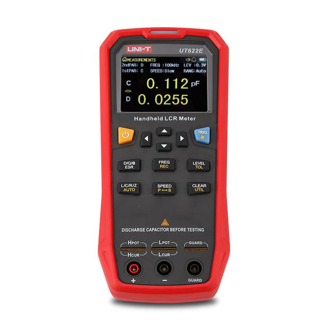
The UT622E handheld LCR meter features powerful functions, high accuracy, fast speed, and long standby time. With a clear and intuitive 2.8-inch TFT LCD display, large-capacity rechargeable battery, and 100 kHz test frequency, the meter can be used for longstanding accurate and convenient measurement in any occasion.
It is suitable for the measurement and screening of inductance, capacitance, and resistance in laboratories, production lines, maintenance points, etc.
Features
Max. test frequency: 100 kHz
Accuracy: 0.1%
Display count: 99999
Max. test rate: 20 times/s
DCR: Yes
Connectivity: Mini-USB
Display: 2.8" TFT LCD
Specifications
Testfrequency
100 Hz, 120 Hz, 1 kHz, 10 kHz, 100 kHz
Test level
0.1 Vmrs, 0.3 Vrms, 1 Vrms
Output impedance
100 Ω
Measurement parameters
Primary: L/C/R/Z/DCRSecondary: D/Q/Θ/ESR
DSR speed test
Fast (20 times/s), medium (5 times/s), or slow (2 times/s)
Range
Auto/Hold
Tolerance range
1%~20%
Equivalent mode
Series/Parallel
Clearing connection
Open/Short circuit
Fuse of test ports
0.1 A/250 V
Communication interface
Mini-USB
MAX reading of primary parameters
99999
MIN resolution
0.0001
Maximum accuracy
0.10%
L
0.00 µH~99.999 H
C
0.00 pF~99.999 mF
Z/R
0.0000 Ω~9.9999 MΩ
ESR
0.0000 Ω~999.99 Ω
D
0.0000~9.9999
Q
0.0000~99999
Θ
-179.9°~179.9°
DCR
0.01 mΩ~20.000 MΩ
Power supply
3.7 V/1800 mAh lithium polymer battery
Display
2.8" TFT LCD (320x240)
Dimensions
93 x 192 x 44 mm
Weight
420 g
Included
UT622E LCR meter
Short circuit board
Four-terminal kelvin test leads
USB cable
Manual
Downloads
Datasheet
Manual
Software
AVR Architecture and Programming An in-depth look at the 8-bit AVR architecture found in ATtiny and ATmega microcontrollers, mainly from a software and programming point of view. Explore the AVR architecture using C and assembly language in Microchip Studio (formerly Atmel Studio) with ATtiny microcontrollers. Learn the details of how AVR microcontrollers work internally, including the internal registers and memory map of ATtiny devices. Program ATtiny microcontrollers using an Atmel-ICE programmer/debugger, or use a cheap hobby programmer, or even an Arduino Uno as a programmer. Most code examples can be run using the Microchip Studio AVR simulator. Learn to write programs for ATtiny microcontrollers in assembly language. See how assembly language is converted to machine code instructions by the assembler program. Find out how programs written in the C programming language end up as assembly language and finally as machine code instructions. Use the Microchip Studio debugger in combination with a hardware USB programmer/debugger to test assembly and C language programs, or use the Microchip Studio AVR simulator. DIP packaged ATtiny microcontrollers are used in this volume for easy use on electronic breadboards, targeting mainly the ATtiny13(A) and ATtiny25/45/85. Learn about instruction timing and clocks in AVR microcontrollers using ATtiny devices. Be on your way to becoming an AVR expert with advanced debugging and programming skills.
Diese Ausgabe steht allen GOLD- und GREEN-Mitgliedern auf der ElektorMagazine-Website zum Download bereit!
Sie sind noch kein Mitglied? Hier klicken!
Audio-DSP-FX-Prozessor-BoardTeil 1: Eigenschaften und Design
50 Jahre Elektor in englischer Sprache
KiCad 8Neue und aktualisierte Funktionen
MultiCalculator-KitEin Elektronikrechner-Bausatz von Elektor mit Arduino
Preiswerte GNSS-RTK-SystemeFür zentimetergenaue Positionsbestimmung
Platinenlayout und SicherheitTipps für sichere und langlebige Leiterplatten
Opamp-TesterFür Audio- und andere Anwendungen
Projekt-Update #4 : Energiemessgerät mit ESP32Energieüberwachung mit MQTT
Echtzeit-Spektrumanalyzer mit Waveguide-Technologie und Multi-Schnittstellen-PCsAaronia etabliert neues Produktsegment und präsentiert erste Prototypen auf der electronica in München
electronica 2024Highspeed und robuste Board-to Board Steckverbinder
InduktivitätenSpulen und Ferrite anwendungsorientiert selektieren
EMI-Abschirmung zur Einhaltung der elektromagnetischen Konformität
Das ultimative Werkzeug für jeden Elektronik-EnthusiastenUnendliche Möglichkeiten mit Red Pitaya und 1.000+ Click Boards™
Die 100 % durchgängige Flussmittelseele
Siglent stellt seine neue Vektornetzwerkanalysator-Plattform SNA6000A vor
HDI der MittelklasseEin neuer ökonomischer PCB Pooling Service für hochpolige BGAs
Ferngesteuerte IoT-EntwicklungDie einzige Lösung für Fernunterricht und Entwicklung in der Embedded-Industrie
Herausforderungen der DFM-Analyse für Flex- und Rigid-Flex-Design
Aus dem Leben gegriffenMikrotechnophobie
Feliz Natal: 3D-WeihnachtsbaumEine 3D-Platine mit preiswertem 32-Bit-Mikrocontroller
Aller Anfang......muss nicht schwer sein: Weiter geht es mit den Opamps!
Ein autonomer SensorknotenProjekt-Update #1: Reduzierung der Leerlauf-Stromaufnahme mit externer RTC mit Leistungsschalter
2024: Eine Odyssee in die KIEin Blick zurück in die Zukunft
LED-Displays mit dem MAX7219Ein praktischer Ansatz für einen großartigen Chip
Projekt 2.0Korrekturen, Updates und Leserbriefe
VibroTactile-HandschuheEin Durchbruch für Parkinson-Patienten?