Quite unintentionally a one-page story on an old Heathkit tube tester in the December 2004 edition of Elektor magazine spawned dozens of ‘Retronics’ tales appearing with a monthly cadence, and attracting a steady flow of reader feedback and contributions to the series. Since launching his Retronics columns, Elektor Editor Jan Buiting has never been short of copy to print, or vintage equipment to marvel at.
This book is a compilation of about 80 Retronics installments published between 2004 and 2012. The stories cover vintage test equipment, prehistoric computers, long forgotten components, and Elektor blockbuster projects, all aiming to make engineers smile, sit up, object, drool, or experience a whiff of nostalgia.
To reflect that our memories are constantly playing tricks on us, and honoring that “one man’s rubbish is another man’s gem”, the tales in the book purposely have no chronological order, and no bias in favor of transistor or tube, microprocessor or discrete part, audio or RF, DIY or professional, dry or narrative style.
Although vastly diff erent in subject matter, all tales in the book are told with personal gusto because Retronics is about sentiment in electronics engineering, construction and repair, be it to reminisce about a 1960s Tektronix scope with a cleaning lady as a feature, or a 1928 PanSanitor box for dubious medical use.
Owners of this book are advised to not exceed one Retronics tale per working day, preferably consumed in the evening hours under lamp light, in a comfortable chair, with a piece of vintage electronic equipment close and powered up.
Elektor GREEN en GOLD leden kunnen deze uitgave hier downloaden.
Nog geen lid? Klik hier om een lidmaatschap af te sluiten.
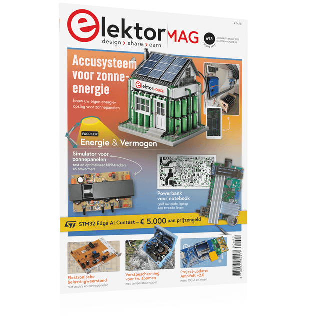
DHZ-accusysteem voor zonne-energiebouw uw eigen energieopslag voor zonnepanelen
Simulator voor zonnepanelentest en optimaliseer MPP-trackers en omvormers
De STM32 Edge-AI-ContestOntdek de nieuwe STM32N6 en ding mee naar € 5000!
Vergroten van de bandgapdaarom is er zoveel interesse in SiC en GaN
Powerbank voor noteboekgeef uw oude laptop een tweede leven
Medische robotshet overwinnen van technische en regelgevende barrières
Vorstbescherming voor fruitbomenmet temperatuurlogger
Het analoge dingde Arduino onder de analoge computers?
Zuinige relaisdriverspaart 90% spoelstroom
Verbetering van de ET5410A+ DC-belastingblijf koel en stil
electronica 2024een terugblik
Elektromagnetische compatibiliteitEMC in een notendop!
Alle begin......filtert actief
Reduceer vermogensverlies met seriecondensatorenslim gebruik van capacitieve reactantie
De betaalbare MCP4725 12-bit digitaal/analoog-omzetterEEPROM-functie zorgt voor veilig inschakelgedrag
FNIRSI LCR-ST1 smart LCR-meetpincet
Raspberry Pi-gebaseerd test- en meetlabals eerste: de ADC
Elektronische belastingweerstandmet onderdelen die u waarschijnlijk hebt liggen
2025: een AI-odysseeenkele projecten voor het nieuwe jaar
Project-update: AmpVolt v2.0100 ampère en meer!
Project 2.0correcties, updates en brieven van lezers
Ethische transparantie ontsluierdinzichten uit het Ethics in Electronics 2024 onderzoek
Audio DSP FX Processor Boarddeel 2: toepassingen maken
If you have the right tools, designing a microprocessor shouldn’t be complicated. The Verilog hardware description language (HDL) is one such tool. It can enable you to depict, simulate, and synthesize an electronic design, and thus increase your productivity by reducing the overall workload associated with a given project.Monte Dalrymple’s Microprocessor Design Using Verilog HDL is a practical guide to processor design in the real world. It presents the Verilog HDL in a straightforward fashion and serves as a detailed introduction to reducing the computer architecture and as an instruction set to practice. You’re led through the microprocessor design process from start to finish, and essential topics ranging from writing in Verilog to debugging and testing are laid bare.The book details the following, and more:
Verilog HDL Review: data types, bit widths/labeling, operations, statements, and design hierarchy
Verilog Coding Style: files vs. modules, indentation, and design organization
Design Work: instruction set architecture, external bus interface, and machine cycle
Microarchitecture: design spreadsheet and essential worksheets (e.g., Operation, Instruction Code, and Next State)
Writing in Verilog: choosing encoding, assigning states in a state machine, and files (e.g., defines.v, hierarchy.v, machine.v)
Debugging, Verification, and Testing: debugging requirements, verification requirements, testing requirements, and the test bench
Post Simulation: enhancements and reduction to practice
Monte Dalrymple received a BSEE (with highest honors) and an MSEE from the University of California at Berkeley, where he was elected to Phi Beta Kappa. Monte started his career at Zilog, where he designed a number of successful products, including the Serial Communication Controller (SCC) family and the Universal Serial Controller (USC) family. He was also the architect and lead designer of the Z380 microprocessor. Monte started his own company, Systemyde International Corp., in 1995, and has been doing contract design work ever since. He designed all five generations of Rabbit microprocessors, a Z180 clone that is flying on the Juno mission to Jupiter, and a Z8000 clone that flies in a commercial avionics air data computer. Monte holds 16 patents as well as both amateur and commercial radio licenses. Monte wrote 10 articles for Circuit Cellar magazine between 1996 and 2010. He recently completed a side project to replace the CPU in an HP-41C calculator with a modern FPGA-based version.
The Siglent SDS1104X-E employs a new generation of SPO (Super Phosphor Oscilloscope) technology that provides excellent signal fidelity and performance. The system noise is also lower than similar products in the industry. It comes with a minimum vertical input range of 500 uV/div, an innovative digital trigger system with high sensitivity and low jitter, and a waveform capture rate of 400,000 frames/ sec (sequence mode).
The SDS1104X-E also employs a 256-level intensity grading display function and a color temperature display mode not found in other models in this class. SIGLENT’s latest oscilloscopes offering supports multiple powerful triggering modes including serial bus triggering. Serial decoding is free and includes IIC, SPI, UART, CAN, and LIN. History waveform recording and sequential triggering enable extended waveform recording and analysis. Another powerful addition is the new 1 Mpt FFT math function that gives the SDS1104X-E very high frequency resolution when observing signal spectra.
Kenmerken
Intelligent trigger: Edge, Slope, Pulse Width, Window, Runt, Interval, Timeout (Dropout), and Pattern
Free Serial bus triggering and decoding:IIC, SPI, UART, RS232, CAN, and LIN
Video triggers and supports HDTV
Low background noise and 500 ?V / div to 10 V / div voltage scales
10 types of one-button shortcuts, supports Auto Setup, Default, Cursors, Measure, Roll, History, Display/Persist, Clear Sweep, Zoom and Print
Segmented acquisition (Sequence) mode, dividing the maximum record length into multiple segments (up to 80,000), according to trigger conditions set by the user, with a very small dead time segment to capture the qualifying event.
History waveform record (History) function, the maximum recorded waveform length is 80,000 frames
Automatic measurement function on 38 parameters, supports Statistics, Gating measurement, Math measurement, History measurement and Ref measurement
1 Mpts FFT
True measurement and math can use all 14 Mpts of memory
Preset key can be customized for user settings or factory “defaults”
Security Erase mode
Highspeed hardware based Pass/ Fail function
Large 7-inch TFT-LCD display with 800 * 480 resolution
Multiple interface types: USB Host, USB Device (USB-TMC), LAN (VXI-11), Pass / Fail, Trigger Out
Supports SCPI remote control commands
Multi-language display and embedded help
Browser control/onboard webpage for software free monitoring (4 channel models only)
Inbegrepen
1x Siglent SDS1104X-E Oscilloscope
4x 100 MHz probes
1x Guarantee Card
1x Power Cord
1x USB Cable
1x Quick Start Guide
Downloads
Datasheet
Manual
Programming Guide
Elektor GREEN en GOLD leden kunnen deze uitgave hier downloaden.
Nog geen lid? Klik hier om een lidmaatschap af te sluiten.
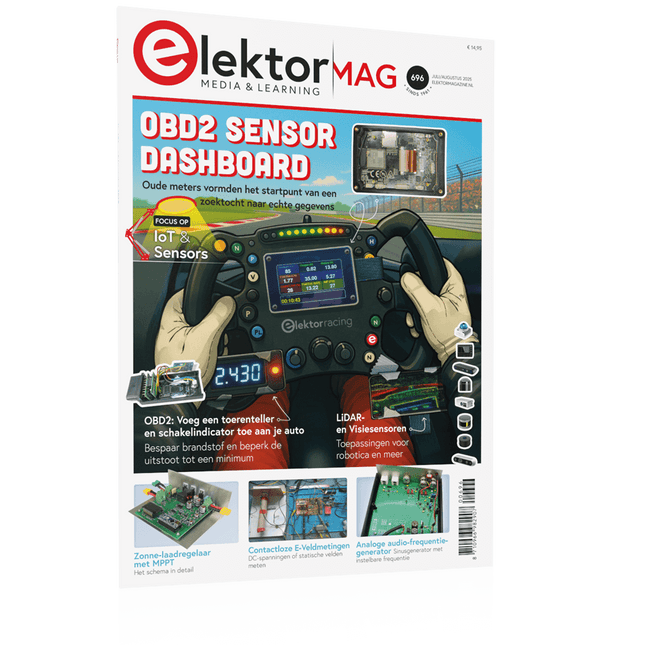
OBD2-sensordashboardOude meters vormden het startpunt van een zoektocht naar echte gegevens
OBD2: voeg een toerenteller en schakelindicator toe aan je autoRetro, maar uiterst nuttig
LiDAR- en Visiesensoren voor Robotica
Sensor+Test 2025 en PCIM 2025
Contactloze E-Veldmetingen (1)Een Trillende Membraan voor het Detecteren van Gelijkspanningen of Statische Elektrische Velden
Draadloze brievenbusmeldervan optische sensoren tot radar: enkele mogelijkheden
Elektor Mini-Wheelieeen zelfbalancerende robot
ZonnecellenVreemde onderdelen, de serie
Aan de slag met een moderne radarsensorStaat een nauwkeurige meting op uw radar?
Uit het leven gegrepenpapierfabriek
CybersecurityZware tijden voor hackers
Infographics: IoT en sensoren 2025
Bluetooth 6.0 brengt verbeterde toepassingen voor afstandsbepalingNieuwe versie biedt betere apparaatpositionerings- en -locatieservices
Draadloze communicatie verkennen met BeagleY-AI
Err-lectronicsCorrecties, updates en lezerspost
Alle begin......sluit het thema opamps af
Een krachtige AI-codeerassistentsneller ontwikkelen met Continue en Visual Studio Code
Zonne-laadregelaar met MPPT (2)Het schema
Ultrasone obstakeldetectoreen eenvoudig project om slechtzienden te helpen
2025: Een AI-odysseeHalfjaaroverzicht
Raspberry Pi Standalone MIDI-synthesizer (3)Het slimmer maken en een gebruikersinterface toevoegen
Meshtastic: een demonstratieprojectEen slim netwerk van LoRa-radio's
Analoge audio-frequentiegeneratorHoogwaardige sinusgenerator met instelbare frequentie
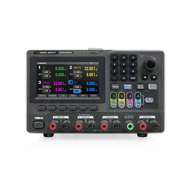
The Siglent SPD4323X is a 4-channel DC Linear Programmable Power Supply equipped with a 4.3-inch TFT-LCD display, friendly human-machine interface, and excellent performance indicators. Real-time waveform display provides engineers with an informative user interface.
SPD4323X offers a total output power of 240 W with a resolution of 1 mV/1 mA. The maximum voltage and current for each channel are as follows:
CH1: 6 V/3.2 A
CH2: 32 V/3.2 A
CH3: 32 V/3.2 A
CH4: 6 V/3.2 A
Kenmerken
Rated output power: 240 W
Rated voltage: 32 V, 12 V, 30 V
Up to four high-precision power supplies with independent controllable outputs, supporting CH2 and CH3 series and parallel connections
Clear graphical interface with waveform and timer display modes
5-digit voltage and current display with minimum resolution of 1 mV, 1 mA
Fast output response time: <50us
The high current channel support remote voltage compensation sense function. The maximum compensation voltage is 0.6 V
Overvoltage protection and overcurrent protection or safe and accurate operation
Equipped with a 4.3-inch TFT-LCD display (480 x 272 resolution)
USB and LAN standard communication
USB-GPIB module is optional
Excellent channel density with up to 4 channels in a 3U half rack package
Internal data storage for setups and parameters
Embedded Web Server with instrument communication that doesn’t require software installation
Fully SCPI programming command set support as well as a LabView driver for remote control and system automation
Specificaties
SPD4323X
SPD4121X
SPD4306X
Channel Output
CH1: Voltage 0 to 6 V Current 0 to 3.2 ACH2: Voltage 0 to 32 V Current 0 to 3.2 ACH3: Voltage 0 to 32 V Current 0 to 3.2 ACH4: Voltage 0 to 6 V Current 0 to 3.2 A
CH1: Voltage 0 to 15 V Current 0 to 1.5 ACH2: Voltage 0 to 12 V Current 0 to 10 ACH3: Voltage 0 to 12 V Current 0 to 10 ACH4: Voltage 0 to 15 V Current 0 to 1.5 A
CH1: Voltage 0 to 15 V Current 0 to 1.5 ACH2: Voltage 0 to 30 V Current 0 to 6 ACH3: Voltage 0 to 30 V Current 0 to 6 ACH4: Voltage 0 to 15 V Current 0 to 1 A
Resolution
1 mV, 1 mA
1 mV, 1 mA
1 mV, 1 mA
Setting Accuracy
Voltage: ±(0.03% of reading+10) mV, Current: ±(0.3% of reading+10) mA
Voltage: ±(0.03% of reading+10) mV, Current: ±(0.3% of reading+10) mA
Voltage: ±(0.03% of reading+10) mV, Current: ±(0.3% of reading+10) mA
Readback Accuracy
Voltage: ±(0.03% of reading+10) mV, Current: ±(0.3% of reading+10) mA
Voltage: ±(0.03% of reading+10) mV, Current: ±(0.3% of reading+10) mA
Voltage: ±(0.03% of reading+10) mV, Current: ±(0.3% of reading+10) mA
Display
4.3" TFT-LCD 5-digit voltage and current display
4.3" TFT-LCD 5-digit voltage and current display
4.3" TFT-LCD 5-digit voltage and current display
Output power
240 W
285 W
400 W
Inbegrepen
1x Siglent SPD4323X Power Supply
1x Power cord (EU)
1x Output test cord (3 A)
1x USB cable
1x Quick start guide
Downloads
Datasheet
Manual
Quick start
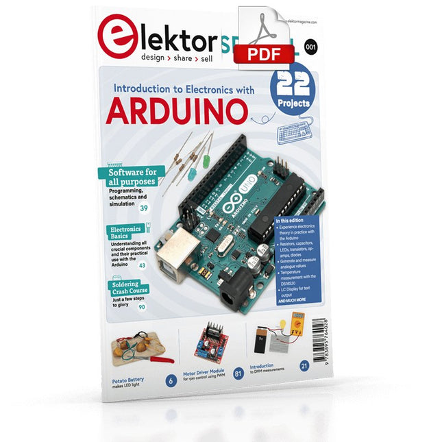
Although the Arduino isn’t a novelty any longer, there are still many beginners who want to try programming and development with a microcontroller, and to them, it is all new. All beginnings can be difficult, though they should be light and enjoyable.
You do not need much or expensive equipment for the examples. The circuits are built on a small breadboard, and, if necessary, connected to an Arduino Uno, which you can program on a Windows PC. You will find clear examples of how to build all circuits, ensuring easy and error-free reproduction.
Projects Discussed
Current & Voltage – How it all began
Arduino Hardware
Arduino Programming
The Electrical Circuit
Measuring with the Multimeter
Circuit Diagrams and Breadboards
Creating Circuit Diagrams
Breadboard Views with Fritzing
Online Circuit Simulation
Indispensable: Resistors (Part 1)
Hands-on with Resistors (Part 2)
Variable Resistors
Diodes: One-way Street for Current
The Transistor Switch
Electromagnetism
Relays and Motors
op-amps: Operational Amplifiers
Capacitors
The NE555 Timer
PWM and Analogue Values with Arduino
7-Segment Temperature Display
Introduction to Soldering and LCDs
The BB830T is a solderless (plug-in) transparent breadboard with 830 connection tie-points (i.e. 830 wire insertion holes). It has 4 power rails. Solderless breadboards are great for building and testing new circuits because parts can be easily inserted and removed. They are completely re-usable. The BB830T has a 630 tie-point IC-circuit area plus four 50 tie-point power rails.
Specifications
830 tie points total: 630 tie-point IC-circuit area plus two 100 tie-point distribution strips providing 4 power rails.
ABS plastic/transparent body with black printed legend. Color legend on distribution strips.
Contacts are Phosphor Bronze with Plated Nickel Finish, rated for 50,000 insertions.
Rated at 36 Volts, 2 Amps.
Insertion Wire Size is 21 to 26 AWG, 0.016 to 0.028 inches diameter (0.4 to 0.7mm diameter).
Peelable adhesive tape backing provided for attaching to a surface. Metal back plate provided.
Elektor GREEN and GOLD members can download their digital edition here.
Not a member yet? Click here.
The RISC-V Open-Source Processor Architecture16 Boards and MCUs You Should Know
An FPGA-Based Audio Player with Equalizer (1)Mixing Digital Audio with an Arduino MKR Vidor 4000
Laser Head for Pico-Based Sand ClockDrawing with Light
Enter the STM32 Edge AI Contest
A Multi-Sensor Environmental Monitoring System for PlantsWireless Measurement of Water Supply and Light Conditions
Maixduino AI-Powered Automatic DoormanFace Detection with a Camera
Embedded Electronics 2024AI Is Set to Redefine the Industry
Charge-Based In-Memory Compute at EnCharge AI
AI Inferencing at 10 Times Lower Power and 20 Fold Lower Cost
Click Board Helps Develop and Train ML Models for Vibration Analysis
The Elektor Mini-WheelieA Self-Balancing Robot Kit
MCU, I See YouMCUViewer Open-Source Multiplatform Debugging Tool
USB 2.0 IsolatorElectrically Isolated Connections for USB Devices
Intervention Before DamagePredictive Maintenance in Practice
SPoE – Electromagnetic CompatibilitySingle-Pair with Power-Over-Ethernet Through the Eyes of EMC
Color TV: A Wonder of Its TimeCreating a New World
ECG Graph MonitoringAn Implementation with Hexabitz Modules and an STM32CubeMonitor
The Battle for AI at the Edge
HaLow Hits Record 16-km Wi-Fi Distance at 900 MHz
First CHERI RISC-V Embedded Chip and Early Access Programme
Third-Generation Wildfire Detection Uses Satellite Links
From Life’s ExperienceChoice Overload
Starting Out in Electronics……Continues Filtering and Controls Tone
Quasi-Analog ClockworkA Remake of an Elektor Classic
A Modular Approach to Sensor TestingThe ESP32-S3-Based Sensor Evaluation Board
2025: An AI OdysseyThe Rise of Foundation Models and Their Role in Democratizing AI
Raspberry Pi Standalone MIDI Synthesizer (1)Preparing a Platform for Some Edge AI Experiments
Err-lectronicsCorrections, Updates, and Readers’ Letters
Universal AI RISC-V Processor Does It All — CPU, GPU, DSP, FPGA
CEO Interview: Ventiva’s Thin and Cool Tech
Dual-Core Programming with a Raspberry Pi PicoVenture Into the World of Parallel Programming
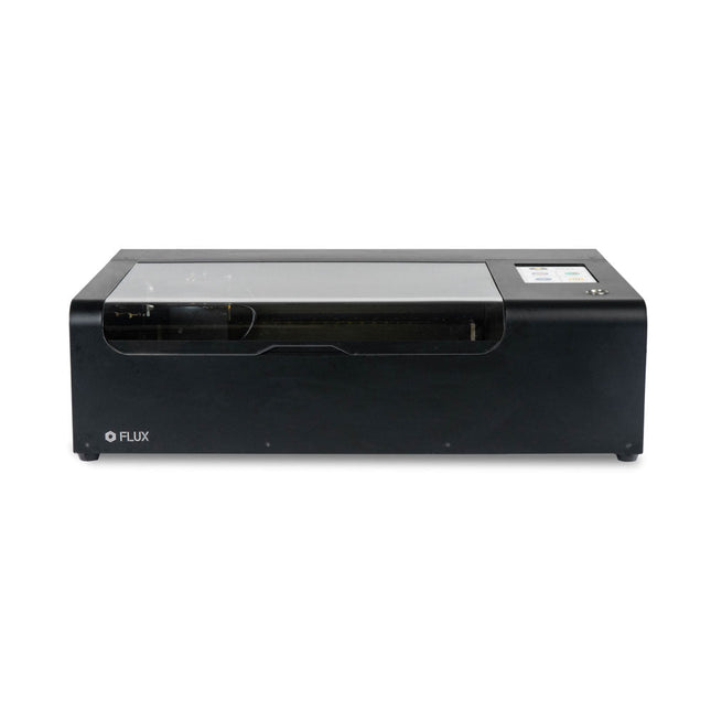
FLUX Beamo is a powerful and compact 30 W CO2 desktop laser cutter that can cut and engrave a range of materials including metals. With its easy-to-use design, intuitive controls and features, you can effortlessly create amazing things.
Built-in HD camera
Cutting and engraving is hassle-free with our preview mode. Place your material, preview the work area in the Beam Studio software and engrave. Your design comes out exactly as shown in the preview.
Integrated safety features
If left opened, auto pause ensures the laser stops. The internal water cooling system provides a stable cutting process. Plus, you can stop production with a single switch at any time.
Powerful high resolution laser
The Beamo ultra thin laser can engrave exceptional detail down to 0.05 mm wide with a clear resolution of 1,000 dpi. Fitting for any craft or small business project.
The most precise compact CO2 laser engraver
Beamo's sleek, modern and compact design fits beautifully in any home, school or workshop space. It comes pre-assembled with a metal body and acrylic lid, measuring 615 x 445 x 177 mm. Bring your designs to life with its 30 W CO2 laser operating on a 30 x 21 cm work area.
Safe for home and school
Beamo prioritises safety with its thoughtful design features. The machine is fully enclosed, and it automatically pauses if the lid is opened during a task. Additionally, there is a single switch for immediate machine shutdown in case of emergencies. Beamo is equipped with a Class 1 laser, which is completely safe under normal use.
Specifications
Dimensions
615 x 445 x 177 mm
Weight
22 kg
Work Area
300 x 210 x 45 mm (11.81 x 8,27 x 1.77")
Camera Preview Area
300 x 195 mm
Voltage
AC 110 V / 220 V
Touch Panel
1024 x 600 LCD
Camera
HD CMOS
I/O
Wi-Fi / Ethernet
Laser Spec
30 W CO? Laser
Laser Moving Speed
0~300 mm/s
Laser Cutting Thickness
0-5 mm (varies by material)
Software Mode
Vector / Graphic (monochrome, gray scale)
Operating System
Windows / macOS / Linux
Software File Type
JPG / PNG / SVG / DXF
Included
FLUX Beamo (distilled water included)
Vent hose Duct Clamp
Double sided tape to align the mirror's
Ethernet cable
Vent Hose
Double head wrench
Wood piece
Torx screwdriver and 2.5 mm hexagonal wrench
Funnel
1x Laser Cutter Lubricant
Power cord
Wifi Dongle USB
Beamo Manual
Honey Comb Platform (30 W)
Downloads
Firmware
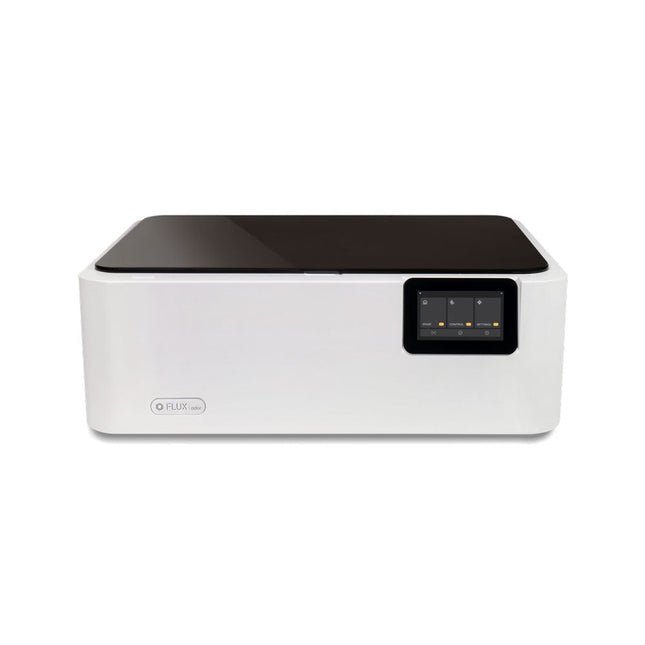
FLUX Ador is the world's first color printing laser cutter. Powered by three high-quality, interchangeable modules, Ador enables you to engrave and cut though a wide range of materials while enhancing your projects with a pop of color.
New creative potential with Ador
Whether you’re an educator, small business, crafter or designer, with Ador, the application boundary is for you to define.
Easy to use
Place material then autofocus
Drag and drop your design
Engrave, cut or print
Project Completed!
Big workspace, big ideas
Ador offers a big working space of 430 x 300 mm, with a depth of 30 mm, expanding the horizons of your creativity.
Specifications
Dimensions
637 x 488 x 226 mm
Weight
19 kg
Work Area
X&Y: 20 W Diode laser: 430 x 300 mm (X & Y varies with different modules)Z: 30 mm (for all modules) & 20 mm (with prism)
Camera Preview Area
Whole work area
Voltage
AC 110-240 V
Touch Panel
Yes, 8 inches (diagonal)
Camera
8 MP
I/O
USB / WiFi
Laser Spec
W Diode laser Module
Laser Moving Speed
0~400 mm/s
Laser Cutting Thickness
Varies for different materials
Software Mode
Vector / Graphic (monochrome, gray scale)
Operating System
Windows / macOS / Linux
Software File Type
JPG / PNG / SVG / DXF
Included
FLUX Ador
20 W diode laser module
6x prism lift
Power adapter
Power cord
Hex key
Vent Hose
Vent hose Duct Clamp
Wooden test piece
Laser Cutter Lubricant
Downloads
Firmware
De FNIRSI TMP-610S is een compact 3-in-1 meetinstrument dat een True RMS-multimeter, een 10 MHz-oscilloscoop en een 50 kHz DDS-signaalgenerator combineert. Het apparaat is ontworpen voor het opsporen van fouten in elektronica, het testen van circuits en ontwikkelingswerkzaamheden, zowel in het laboratorium als onderweg.
De multimeter biedt een resolutie van 60.000 counts en ondersteunt metingen van spanning, stroom, weerstand, capaciteit, frequentie, temperatuur, diodes en continuïteit. De geïntegreerde oscilloscoop maakt realtime golfvormanalyse mogelijk met een snelheid tot 48 MSa/s, terwijl de signaalgenerator 13 golfvormtypen ondersteunt met instelbare frequentie, amplitude en duty cycle.
Dankzij een 3,5-inch IPS-touchscreen, slimme autoscan-functie, Bluetooth-connectiviteit voor DMM-functies, opslag van golfvormen, USB-exportmogelijkheid en een oplaadbare accu van 3000 mAh is de TMP-610S een veelzijdige alles-in-één-tool voor elektronicaprofessionals en hobbyisten.
Kenmerken
3-in-1 ontwerp: DMM + oscilloscoop + signaalgenerator
Uiterst nauwkeurige True RMS-meting (60.000 counts)
10 MHz-oscilloscoop met een samplefrequentie van 48 MSa/s
Synchronisatie met Bluetooth-app (alleen multimeterfunctie)
3,5-inch slim touchscreen met diverse weergavemodi
50 kHz DDS-signaalgenerator met 13 golfvormen
Ingebouwde zekering voor eenvoudige vervanging
Specificaties
Multimeter
Functie
Bereik
Nauwkeurigheid
DC voltage
600mV/6V/60V/600V/1000V
±(0.03%+5d)
AC voltage
600mV/6V/60V /600V/750V
±(0.3%+15d)
DC current
600uA/6000uA/60mA/600mA
±(0.15%+5d)
6A/10A
±(0.2%+5d)
AC current
600uA/6000uA/60mA/600mA
±(0.5%+15d)
6A/10A
±(0.75%+15d)
Resistance
600Ω/6KΩ/60KΩ/600KΩ/6MΩ
±(0.1%+5d)
60MΩ
±(0.2%+10d)
Capacitance
60nF/600nF/6uF/60uF
±(2.5%+30d)
600uF/6mF/60mF
±(3.5%+30d
Frequency
10 Hz~60 MHz
±(0.01%+5d)
Temperature
-40℃~1000℃
±(1.0%+5℃)
Continuity
0Ω~1KΩ
±(0.2%+5d)
Diode
0V~3.0V, 0Ω~1 Ω
±(1%+5d)
AC frequency response
10KHz
/
Oscilloscoop
Real-time Sampling Rate
48 MSa/s
Analog Bandwidth
10 MHz
Input Impedance
1MΩ
Coupling Mode
AC/DC
Test Voltage Range
1:1 Probe - 80Vpp (±40V)
10:1 Probe - 800Vpp (±400V)
Vertical Sensitivity
10mV/div~10V/div
Vertical Displacement
Adjustable with indication
Horizontal Time Base Range
50 ns ~ 20 s
Trigger Mode
Auto, Normal, Single
Trigger Type
Rising, Falling, 50%
Trigger Level
Adjustable with indication
Measurement Parameters
Freq, Period, +Duty, ‒Duty, +Width, ‒Width, Max, Min, P‒P, Amp, RMS, Avg
Persistence
Off / 500ms / 1s / ∞
Cursor Measurement
Yes
Waveform Screenshot Saving
Yes
Signaalgenerator
Output Waveform
Supports 13 waveform types
Frequency
0~50kHz
Amplitude
0.0V~3.0V
Duty Cycle
0~100%, adjustable for Square and Sawtooth waves
Inbegrepen
1x FNIRSI TMP-610S multimeter + oscilloscoop + signaalgenerator
1x P6100-sonde
1x Adapter
2x Krokodillenklemmen
2x Multimetersondes
Probe-accessoires
1x Opbergtas
1x USB-C kabel
1x Manual
Downloads
Manual