
Zoekresultaten voor "fm or radio or kit"
-

Elektor Labs Elektor Low-noise Labvoeding
De low-noise labvoeding van Elektor is een volledig analoge, instelbare, symmetrische unit met gemiddeld vermogen, zonder schakelende of digitale componenten. De uitgangsspanning is instelbaar tussen 0 V en ±22 V, en de uitgangsstroom kan worden ingesteld van 0 A tot 1 A. Doordat elke vorm van schakeltechniek wordt vermeden, levert het ontwerp extreem weinig ruis. Voor de weergave van beide uitgangsspanningen en -stromen worden vier kleine analoge paneelmeters met draaispoel gebruikt. De meeste moderne laboratoriumvoedingen en AC-adapters maken gebruik van schakelende technieken. Zelfs de beste uitvoeringen vertonen onvermijdelijk hoogfrequente rimpel en andere schakelartefacten op hun uitgang, die het testen van gevoelige analoge schakelingen kunnen verstoren en metingen van kleine signalen kunnen beïnvloeden. Om dit te voorkomen, is het concept hier een volledig analoge voeding. Hoewel deze minder efficiënt is dan vergelijkbare schakelende voedingen, is de lagere efficiëntie bij gebruik op de testbank nauwelijks van belang en zorgt deze voor schonere en betrouwbaardere meetresultaten. Omdat veel analoge schakelingen een symmetrische voeding vereisen, levert dit ontwerp positieve en negatieve uitgangsspanningen van gelijke grootte. Een kleine hoeveelheid afregeling is beschikbaar om eventuele onbalans te compenseren. Uiteraard is ook een instelbare stroombegrenzing aanwezig. De kit bevat de onderdelen die nodig zijn om de voeding te bouwen, met uitzondering van de transformatoren. Specificaties Uitgangsspanning 0…+22 V, 0, −22 V Uitgangsstroom 0…+1 A, 0…−1 A Ruis −85 dBV (bij 0,95 A/20 V, B = 22 kHz) −84 dBV (bij 0,95 A/20 V, B > 500 kHz) Rimpelspanning 50 µVRMS (bij 950 mA/20 V, B = 22 kHz, voornamelijk 100-Hz-component) Inbegrepen 3x printplaten: regelaar (PCB-1), netfilter (PCB-2) en transformator (PCB-3) Alle componenten, behalve de AC-transformatoren 4x draaispoelmeters Extra onderdelen voor de bedrading (draden, banaanstekkerbussen, IEC-voedingsmodule, enz.) Niet inbegrepen De drie AC-transformatoren Een behuizing Onderdelenlijst Voor de regelaar-printplaat (240386-1) Weerstanden (250 mW, 1%) R1 = 12 Ω R2, R8, R37, R62 = 1 MΩ R3, R7, R10, R13, R17, R20, R22, R30, R35, R42, R45, R47, R55, R60 = 100 Ω, 600 mW R4, R5 = 4.7 kΩ R6 = 100 kΩ R9, R12, R14, R36, R38, R39, R61, R63, R66, R72, R78, R79 = 10.0 kΩ, 600 mW R11 = 9.76 kΩ, 600 mW R15, R40 = 44.2 kΩ, 600 mW R16, R41, R77 = 1 kΩ R18, R43 = 1.5 kΩ, 1 W, 5% R19, R44 = 470 Ω, 1 W, 5% R21, R46 = 330 Ω, 600 mW R23, R24, R48, R49 = 1.0 Ω, 1 W R25, R50 = 1 kΩ, 1 W, 5% R26, R28, R51, R53 = 1.000 kΩ 0.1%, 15 ppm/C R27, R29, R52, R54 = 10.00 kΩ 0.1%, 15 ppm/C R31, R56 = 1.2 kΩ, 1 W, 5% R32, R57 = 47 kΩ R33, R58 = 270 Ω R34, R59 = 27 kΩ R64, R69 = 12.0 kΩ R65 = 3.0 kΩ, 600 mW R67, R80 = 470 Ω, 600 mW R68, R70 = 6.8 kΩ, 600 mW R71 = 30.0 kΩ,, 600 mW R73, R74, R75, R76 = 10 MΩ P1, P2, P3 = 10 kΩ, 200 mW, 20%, potentiometer, 1 turns, single, lin., panel mount P4, P5 = 500 Ω, 500 mW, 10%, trimmer, 25 turns, 3296Y-1-501LF Bourns P6, P7 = 10 kΩ, 500 mW, 10%, trimmer, 25 turns, 3296Y-1-501LF Bourns Condensatoren C1 = 100 nF, 50 V, 10%, ceramic X7R, LS 5 mm C2, C3, C6, C7, C30 = 10 µF, 63V, 20%, LS 2.5 mm, 3000hours@105°C C4, C5, C8, C9, C13, C14, C18, C19, C23, C24, C28, C29, C31, C32, C38, C39 = 100 nF, 250 V, 10%, PET, LS 7.5 mm C10, C20 = 47 nF, 100 V, 5%, PET, LS 5 mm C11, C21 = 10 nF, 100 V, 5%, PET, LS 5 mm C12, C22 = 220 µF, 35 V, 20%, 0.024 Ω, LS2.5/3.5 mm, Ir 3.4 A, 2000hours@125°C, polymer C15, C25 = 120 µF, 50 V, 20%, ESR 0.02 Ω, Diam. 10 mm max., LS 5 mm C16, C26 = 15 nF, 100 V, 5%, PET, LS 5 mm C17, C27 = 47 nF, 100 V, 5%, PET, LS 5 mm C33, C34 = 22 µF, 50 V, 20%, LS 2 mm, 10000 hours @ 105°C C35, C36, C44, C45 = 1 µF, 100 V, 10%, LS 5 mm, ceramic X7R C37 = 100 uF, 50 V, 20%. LS 3.5 mm C40, C41, C42, C43, C46, C47, C48, C49 = 1000 µF, 50 V, 20%, LS 5/7.5 mm, Ir 3.32 A, 10000hours@105°C, D 16 mm C50, C51, C52, C53 = 47 nF, 100 V, 10%, ceramic X7R, LS 5 mm Spoelen L1, L2 = 4.7 µH, 3.2 A, 0.033 Ω, LS 5 mm, RLB0914-4R7ML Bourns L3 = Commom mode choke, 14.5 mH, 3 A, SSRH24NH-30145 Kemet Halfgeleiders D1, D2, D3, D4, D5, D9, D10, D11, D15 = BAT85, DO-34 D6, D7, D12, D13 = SR560, DO-201AD D8, D14, D16 = 1N4148, DO-35 D17 = Zenerdiode, 5.6 V, 0.5 W, DO-41 D18, D19 = 1N4004, DO-41 D20, D21 D22, D23 = V30100CI-M3/P, dual common cathode, TO-220 D24 = Zener diode, 30 V, 1 W, DO-41 LED1, LED2 = LED, red, T-1 (3 mm) LED3, LED4 = LED, green, T-1 (3 mm) TVS1, TVS2 = BZW50-33B, R6 T1, T2, T4 = BC337.25, TO-92 T3 = NJW0302G, TO-3P T5, T6, T8 = BC327.25, TO-92 T7 = NJW0281G, TO-3P T9 = BD139, TO-126 (SOT-32) IC1 = LM334Z, TO-92 IC2 = LM4040AIZ-5.0/NOPB, TO-92 (TO-226AA-3) IC3, IC4 = OPA2992IDR, SOIC-8 IC5, IC6 = OPA4992IDR, SOIC-14 IC7 = OPA992IDBVR, SOT-23-5 IC8 = LM339N, DIP-14 IC9 = LM317, TO-220 IC10 = LM337, TO-220 Overige F1, F2 = 5×20 mm fuse, 1.6 A, fast acting HS1, HS2 = Heatsink MC33271 (for T3/T7), 2.7°C/W, PCB mount, height 63.5 mm K1, K4 = 3-way screw terminal block, LS 3.5 mm, max. 1.5 mm² K2, K3 = 3-way screw terminal block, LS 3.5 mm, max. 1 mm² M1, M3 = Moving coil meter, Range 30 V, type 91C4, 45×45 mm M2, M4 = Moving coil meter, Range 1 A, type 91C4, 45×45 mm² RE1 = Relay DPDT,5V, UA2-5NU Diversen 3× 3-way screw terminal block, LS 3.5 mm, max. 1 mm² (for P1, P2, P3) 4× Pin header, 1×2, vertical, pitch 2.54 mm (for LED1, LED2, LED3, LED4) 4× Pin socket, 1×2, vertical. pitch 2.54 mm (for LED1, LED2, LED3, LED4) 2× Heatsink FK222SA220, 20°C/W, PCB mount (for IC9 & IC10) 2× Mica thermal pad for TO-220, 12×18×0.05 mm (for IC9 & IC10) 2× Insulating bushing IB 6, TO-220 (for IC9 & IC10) 2× Ceramic thermal pad, 23×20×2 mm (for T3 & T7) 2× PCB Fuse Holder, for 5×20 mm fuse, 10 A (for F1, F2) 2× Cover for PCB Fuse Holder, transparent (for F1, F2) 2× 2-way screw terminal block, LS 3.5 mm, max. 1 mm² (for M1 & M3) 2× 2-way screw terminal block, LS 3.5 mm, max. 1.5 mm² (for M2 & M4) 8× M3 solder lug, thickness 0.35 mm (for M1…M4) M4 solder lug, thickness 0.35 mm (to connect 4 mm banana connectors) Screened cable, 1 pair, 2×24 AWG/0.22 mm², 1 m (for P1, P2 & P3) IC socket, DIP, 14 contacts (for IC8) M3 washer, plain, steel M3 screw, 16 mm, steel, pan head M3 nut M3 spring washer 50 mm M3 standoff, steel, male-female 12 mm M3 standoff, steel, male-female 10 mm M3 standoff, steel, male-female M3 screw, 8 mm, steel, pan head Voor de netfilter-printplaat (240386-2) Weerstand R1 = 220 kΩ, 1 W, 500 V, 5% Condensatoren C1, C2 = 470 nF, 305 VAC, Class X2, 11 × 27 mm max., LS 15/22.5 mm C3, C4, C5, C6 = 2.2 nF, 300 VAC, Class Y2, 13 × 4 mm, LS 10 mm, PP Spoelen L1, L2 = Common-mode choke, 6.8 mH, 1.7 A, TDK B82732R2172B030 Halfgeleider MOV1 = TVS varistor, 300 VAC, S14K300 (230 VAC, B72214S0301K101) and SK14K150 (150 VAC, B72214S0151K101) Overige K1, K2 = 3-way screw terminal block, LS 7.62 mm F1 = Time-delay fuse, 0.5 A (230 VAC) or 1 A (115 VAC) Diversen 1× Fuse holder, 5×20 mm, 10 A, 500 VAC 1× Transparent fuse cover 4× 10 mm M3 standoff, steel, male–female 4× M3 screw, 8 mm, steel, pan head 4× M3 nut Voor de transformator-printplaat (240386-3) Weerstanden R1, R2 = 2.7 kΩ, 600 mW, 1% R3 = 10.0 kΩ, 600 mW, 1% Condensator C1 = 220 µF, 50 V, 20%, Ø10 mm, LS 5 mm, 4000 h @ 105°C Transformatoren (niet inbegrepen in deze kit!) TR1, TR2, TR3 = 2×7 V, 25 VA, PCB-mounted toroid, 70060K Talema Halfgeleiders D1–D4 = 1N4148, DO-35 D5, D6 = 1N4004, DO-41 D7 = Zener 5.6 V, 1.3 W, DO-41 LED1 = LED, red, T-1 (3 mm) IC1, IC2 = MOC8021M, CTR ≥ 1000%, DIP-6 Overige F1, F2, F3 = 160 mA time-delay fuse (230 VAC) or 315 mA time-delay fuse (115 VAC) K1 = 2-way screw terminal block, LS 7.62 mm K2 = 3-way screw terminal block, LS 3.5 mm, max 1.5 mm² K3, K4 = 3-way screw terminal block, LS 3.5 mm, max 1 mm² RE1, RE2 = Relay DPDT, 5 A/250 VAC / 24 VDC Diversen 1× Pin header 1×2, pitch 2.54 mm + matching socket for LED1 3× Fuse holder 5 × 20 mm, 10 A, 500 VAC + transparent cover 3× M4 screw, 8 mm, pan head + washer for TR1-TR3 8× M3 screw, 8 mm, pan head + nut + washer 8× 10 mm M3 standoff, steel, male–female 2× IC socket, DIP-6 for IC1 & IC2 Extra onderdelen 1 m red insulated wire, stranded, 1.5 mm² 0.5 m blue insulated wire, stranded, 1.5 mm² 0.5 m black insulated wire, stranded, 1.5 mm², 0.5 m 2 m red insulated wire, stranded, D 0.56 mm (0.25 mm²) 2 m black insulated wire, stranded, D 0.56 mm (0.25 mm²) 0.5 m Multicore Cable, Flexible, 3 Core, 0.75 mm² (24 x 0.2 mm) Red banana socket Black banana socket Blue banana socket Green banana socket IEC Power Entry Module with switch, IEC C14 3 crimp terminals, FASTON, 4.75 x 0.81 mm 3 knobs Links Elektor Labs JumpStarter Page Artikel (deel 1) Artikel (deel 2)
€ 299,00€ 249,00Beste prijs
-

tinySA tinySA Ultra+ ZS407 Spectrumanalyzer
The tinySA Ultra+ ZS-407 is a compact, handheld spectrum analyzer and signal generator. Covering 100 kHz to 7.3 GHz in Ultra mode, it lets you visualize and analyze RF signals from HF right through many modern wireless bands – and can even spot signals up to ~12 GHz thanks to harmonic tracking. The intuitive 4-inch resistive touchscreen and rechargeable battery make it great for fieldwork, while features like a built-in signal generator, switchable bandpass filters, step attenuator, USB-PC control and auto-calibration add serious versatility. Kenmerken Screen size: 4 inch (480 x 320) Spectrum Analyzer for 0.1-900 MHz or, with Ultra mode enabled up to 7.3 GHz, level calibrated up to 7.3 GHz. Can observe signals up to 12 GHz Signal Generator with sine wave output between 0.1-900 MHz or square wave up to 6.3 GHz or RF test signal output up to 7.3 GHz when not used as Spectrum Analyzer. Switchable resolution bandpass filters from 200 Hz to 850 kHz Built-in 20 dB optional LNA Color display showing max 450 points providing gapless covering up to the full frequency range. MicroSD card slot for storing measurements, settings and screen captures. Specificaties (Spectrumanalyzer) Input frequency range from 100 kHz to 900 MHz in normal mode and up to 7.3 GHz with ULTRA mode enabled Input impedance 50 ohm when input attenuation set to 10 dB or more. Selectable manual and automatic input attenuation between 0 dB and 31 dB in 1 dB steps when LNA not active Maximum +/-5V DC input Absolute maximum input level of +6 dBm with 0 dB internal attenuation Absolute maximum short term peak input power of +20 dBm with 30 dB internal attenuation Suggested maximum input power of +0 dBm with internal attenuation in automatic mode For best measurements keep input power below -25 dBm Input Intercept Point of third order modulation products (IIP3) of +15 dBm with 0 dB internal attenuation 1 dB compression point at -1 dBm with 0 dB internal attenuation Power detector resolution of 0.5 dB and linearity versus frequency of ±2 dB below 5.3 GHz, ±5dB between 5.3 GHz and 6 GHz Minimum burst length for correct level measurement at 850 kHz RBW in zero span mode of 50 microseconds Absolute power level accuracy after power level calibration of ±2 dB Built-in optional 20 dB LNA with Noise Figure of 5 dB up to 6 GHz Lowest discernible signal without LNA at 30 MHz using a resolution bandwidth of 30 kHz of -102 dBm Lowest discernible signal with LNA at 30 MHz using a resolution bandwidth of 200 Hz of -145 dBm Frequency accuracy equal to the selected resolution bandwidth Phase noise at 30 MHz of -108 dB/Hz at 100 kHz offset and -115 dB/Hz at 1MHz offset Spur free dynamic range when using a 30 kHz resolution bandwidth of 70 dB Resolution filters with a width of 0.2, 1, 3, 10, 30, 100, 300, 600 and 850 kHz On screen resolution of 51, 101, 145, 290 or 450 measurement points. Scanning speed of over 1000 points/second using largest resolution filters. Automatic optimization of actual scanning points to ensure coverage of the whole scan range regardless of the chosen resolution bandwidth Spur suppression option for assessing if certain signals are internally generated or actually present in the input signal Headphone output for listening to the demodulated audio (AM only). Stereo connector with or without microphone, high impedance is louder, short protected Specificaties (Signaalgenerator) Sine wave output with harmonics below -40 dB of fundamental from 100 kHz to 900 MHz Output level selectable in 1 dB steps between -115 dBm and -19 dBm Above 800 MHz choice of two output modes: Cleanest signal mode: square wave, up to 6 GHz with coarse frequency steps and less accurate output level Highest accuracy mode: reduced harmonics with possibly strong spurs up to 7.3 GHz with frequency resolution equal to below 800 MHz and fine output level steps Level accuracy ±2 dB up to 800 MHz between -72 dBm and -19 dBm, less accuracy below -72 dBm, even less accuracy below -110 dBm Output frequency resolution 57.2 Hz Optional AM or FM modulation frequencies between 50 Hz and 5 kHz (AM) or 1 kHz (FM) or sweep over selectable frequency span AM modulation depth between 10% and 100% FM deviation between 1 kHz and 300 kHz Optional output level sweep over maximum the entire output level range Inbegrepen 1x tinySA Ultra+ ZS407 Spectrum Analyzer 2x SMA connection cables 1x Barrel connector 1x Antenna with SMA connector 1x USB-C cable 1x microSD card (32 GB) Downloads Wiki
€ 196,02
-

Elektor Digital Elektor Green Lidmaatschap
Elektronica leren, ontwikkelen en begrijpen – met Elektor Projecten, vakkennis, toegang tot het archief en exclusieve kortingen – alles in één lidmaatschap Wilt u elektronica leren, uw eigen schakelingen ontwikkelen en moderne technologieën beter begrijpen? Elektor Magazine behoort al 65 jaar tot de toonaangevende informatiebronnen voor elektronica-ingenieurs, ontwikkelaars, start-ups en bedrijven. Met een Elektor Green Lidmaatschap verzekert u zich van: ✅ Het internationale elektronica-vakblad Elektor (als digitale uitgave) ✅ Toegang tot het Elektor-archief met 65 jaar elektronica-knowhow ✅ Zelfbouwprojecten, geteste schakelingen, in-depth reviews en tutorials ✅ Exclusieve ledenkortingen op Elektor.nl Waarom Elektor? Al 65 jaar staat Elektor voor gedegen elektronica-kennis, praktijkgerichte projecten en innovatieve technologieën. Van microcontrollers en embedded systemen tot Raspberry Pi, Arduino en ESP32, en van IoT, AI en meettechniek tot audio, RF en robotica: Elektor bestrijkt de belangrijkste platforms en toepassingsgebieden van moderne elektronica. Of u nu beginner, maker of professional bent – met Elektor tilt u uw vaardigheden naar een hoger niveau. Voor wie is het lidmaatschap bedoeld? Beginners – Stap de wereld van de elektronica binnen met begrijpelijke basisprincipes en eerste projecten Makers – Ontdek nieuwe projecten, ideeën en inspiratie voor uw eigen ontwikkelingen Professionals & ingenieurs – Blijf op de hoogte van de nieuwste technologieën en verdiep uw vakkennis Uw voordelen in één oogopslag Tijdschrift (digitaal) – Ontvang elke uitgave digitaal rechtstreeks in uw mailbox 65 jaar kennis van elektronica – Krijg op elk moment toegang tot het uitgebreide Elektor-archief Praktijk & projecten – Breng uw eigen ideeën tot leven met handleidingen, schakelingen en tutorials Exclusieve kortingen – Bespaar bij elke aankoop op Elektor.nl Ontgrendel nu alle Elektor-voordelen! Free Lidmaatschap Green Lidmaatschap ❌ 8× Elektor Magazine (Digitale editie) als PDF ✅ 8× Elektor Magazine (Digitale editie) als PDF ❌ 12 maanden toegang tot het Elektor-archief ✅ 12 maanden toegang tot het Elektor-archief ❌ Toegang tot meer dan 5.000 Gerber-bestanden ✅ Toegang tot meer dan 5.000 Gerber-bestanden ❌ 10% ledenkorting op Elektor.nl ✅ 10% ledenkorting op Elektor.nl ✅ Lees Elektor wekelijks elke vrijdagochtend ✅ Lees Elektor wekelijks elke vrijdagochtend ℹ️ Leest u Elektor liever in gedrukte vorm? Hier vindt u alles over het Elektor Gold-lidmaatschap (print).
€ 89,95 - € 169,95
-

Elektor Digital The ESP32 Cheap Yellow Display Book (PDF)
Projects Using Arduino IDE and the LVGL Graphics Library The ESP32 is probably one of the most popular microcontrollers used by many people, including students, hobbyists, and professional engineers. Its low cost, coupled with rich features makes it a popular device to use in many projects. Recently, a board called the ESP32 Cheap Yellow Display (CYD for short) is available from its manufacturers. The board includes a standard ESP32 microcontroller together with a 320x240 pixel TFT display. Additionally, the board provides several connectors for interfaces such as GPIO, serial port (TX/RX), power and Ground. The inclusion of a TFT display is a real advantage as it enables users to design complex graphics-based projects without resorting to an external LCD or graphics displays. The book describes the basic hardware of the ESP32 CYD board and provides details of its on-board connectors. Many basic, simple, and intermediate-level projects are given in the book based on the ESP32 CYD, using the highly popular Arduino IDE 2.0 integrated development environment. The use of both the basic graphics functions and the use of the popular LVGL graphics library are discussed in the book and projects are given that use both types of approaches. All the projects given in the book have been tested and are working. The block diagram, circuit diagram, and the complete program listings and program descriptions of all the projects are given with explanations. Readers can use the LVGL graphics library to design highly popular eye-catching full-color graphics projects using widgets such as buttons, labels, calendars, keypads, keyboards, message boxes, spinboxes, sliders, charts, tables, menus, bars, switches, drop-down lists, animations, and many more widgets.
€ 29,95
Leden: € 26,96
-

Elektor Academy Pro Raspberry Pi Pico with Arduino C/C++ (programmeercursus)
Deze complete microcontroller-programmeercursus op basis van de Raspberry Pi Pico bevat een leerboek, een componentenkit, praktische projecten en een uitgebreide online cursus met simulaties. Ideaal om embedded systems stap voor stap te leren programmeren met Arduino via een praktische hands-on aanpak. Een praktische introductie tot embedded systems met de Raspberry Pi Pico Deze cursus is ontworpen voor beginners in embedded systems die op zoek zijn naar een gestructureerde en voorbeeldgerichte start. Een kit met LED’s en weerstanden, schakelaars, sensoren en actuatoren, displays, een breadboard en draden is inbegrepen. Deze worden in de cursus gebruikt om voorbeeldtoepassingen te demonstreren. Er is geen voorkennis van Arduino of embedded ontwikkeling vereist. Elke sectie bevat praktische voorbeelden en mini-projecten om belangrijke concepten te versterken en verdere verkenning te stimuleren. Aan het einde van de cursus kunt u niet alleen de voorbeelden reproduceren, maar ook uitbreiden met uw eigen ideeën en toepassingen. Wat leert u? Microcontroller programmeren in C/C++ met de Raspberry Pi Pico met behulp van de Arduino IDE Werken met digitale I/O, knoppen en encoders uitlezen, LED’s en relais aansturen Analoge ingangen, spanningen en sensoren uitlezen Genereren van analoge uitgangssignalen en PWM Gebruik van seriële communicatie zoals UART, I²C en SPI om displays aan te sturen en digitale sensoren en SD-kaarten uit te lezen Tijdbeheer Werken met interrupts Realtime sensorinput en besturing via knoppen, LED’s en displays Aansturen van actuatoren zoals relais en servomotoren Voor wie is dit? Studenten en zelflerenden die embedded systems willen ontdekken Makers en IoT-enthousiastelingen die hun hardwarevaardigheden willen verbeteren Docenten en trainers die kant-en-klaar lesmateriaal zoeken Wat zit er in de doos? Toegang tot de volledige cursus op het Elektor Academy Pro leerplatform Raspberry Pi Pico microcontrollerboard + USB-kabel Boek: Programming Microcontrollers in C/C++ Using Arduino Downloadbare projectbestanden voor elke module Componentenkit: 2× LED, rood, 5 mm LED, groen, 5 mm 3× weerstand, 470 Ω, 0,25 W LDR Potentiometer, 10 kΩ, lineair Drukknop Rotary encoder module Relaismodule DHT22 temperatuur- en vochtigheidssensor TM1637-compatibel 4-digit 7-segment display MPU-6050 IMU met headers SSD1306-compatibel I²C OLED display Micro SD-kaartadapter met header Buzzer SG90 micro servo ILI9341-compatibel SPI 240×320 TFT display 20× jumper wires Breadboard Alle programmeercursussen (en verschillen in inhoud) Cursus Arduino Raspberry Pi Pico with Arduino C/C++ ESP32 with Arduino C/C++ Raspberry Pi Pico with MicroPython ESP32 with MicroPython Online cursus Access to Arduino Course Access to Pico with Arduino C/C++ Course Access to ESP32 with Arduino C/C++ Course Access to Pico with MicroPython Course Access to ESP32 with MicroPython Course Board Uno R3 Raspberry Pi Pico ESP32 Raspberry Pi Pico ESP32 Boek Programming Microcontrollers in C/C++ Using Arduino Programming Microcontrollers in C/C++ Using Arduino Programming Microcontrollers in C/C++ Using Arduino Programming Microcontrollers in MicroPython Programming Microcontrollers in MicroPython Kit 40-delige componenten-kit 40-delige componenten-kit 40-delige componenten-kit 40-delige componenten-kit 40-delige componenten-kit
€ 69,95
Leden: € 62,96
-

Elektor Publishing Les oscilloscopes anciens & modernes pour les débutants
Ce qui se passe en électronique est par définition invisible à l'oeil nu. L'instrument qui permet précisément de rendre visibles les signaux électriques, celui par le truchement duquel les effets de l'électronique se manifestent à nous, c'est l'oscilloscope. Hélas, quand on commence à faire de l'électronique, c'est souvent sans oscilloscope. Et l'on en est réduit à tâtonner, aussi bien physiquement que mentalement. Le jour où l'on goûte à la visualisation des signaux sur un écran, c'est une révélation. Plus personne ne souhaite se priver de cet enchantement. Pas de retour en arrière. En électronique, si l'on veut progresser dans le plaisir et dans la compréhension, il faut un oscillo. Commence alors une période d'interrogation : comment choisir ? Et à peine cette question-là aura-t-elle trouvé sa réponse, il en viendra une ribambelle d'autres que l'on peut résumer en une seule : comment se servir de l'oscilloscope de telle sorte que ce qu'il affiche corresponde bien à la réalité des signaux ? Dans ce livre, Rémy Mallard, répond clairement à ces questions. Il donne aussi de nombreuses informations pour aider son lecteur à élucider lui-même de nouveaux mystères qui ne manqueront pas de surgir. Ceux qui le connaissent déjà comme l'auteur d'un livre sur l'électronique dont le titre est un programme à lui tout seul : L'électronique pour les débutants qui sèchent les cours mais soudent sans se brûler les doigts, ainsi que d'un livre d'initiation à la programmation des microcontrôleurs PIC, savent qu'ils trouveront ici un ouvrage utile, qu'ils rouvriront souvent.
€ 44,95
Leden: € 40,46
-
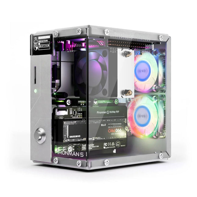
SunFounder Pironman 5 NVMe M.2 SSD PCIe Mini PC-behuizing voor Raspberry Pi 5
Verbeter je Raspberry Pi 5 met de Pironman 5, gebouwd met stevig aluminium, superieure koeling, NVMe M.2 SSD-ondersteuning, OLED-display, RGB-verlichting, standaard HDMI-poorten x2 en een veilige aan/uit-schakelaar. Het is perfect voor NAS, Home Assistant, Media en Game Centers. De Pironman 5 is niet zomaar een behuizing; het is een upgrade die uw Raspberry Pi 5 verandert in een krachtig, efficiënt en stijlvol apparaat. De Pironman 5 bevat de Pi 5 NVMe PIP (PCIe Peripheral Board), een PCIe-adapterkaart die speciaal is ontworpen voor NVMe solid-state drives. Dit bord ondersteunt NVMe SSD's in vier formaten: 2230, 2242, 2260 en 2280, die allemaal in een M.2 M key-slot kunnen worden geïnstalleerd. De verbinding is gecertificeerd voor Gen2.0-snelheden (5 GT/sec), maar kan worden geforceerd naar Gen 3.0 (10 GT/sec) voor snellere prestaties. Uitbreidbaar NVMe M.2 SSD-slot Verbeter de prestaties van uw Raspberry Pi 5 met de NVMe M.2 SSD-sleuf van de Pironman 5, die meerdere formaten ondersteunt (2230, 2242, 2260, 2280) voor meer opslag en snellere systeemreactie. Geavanceerd koelsysteem Houd je Raspberry Pi 5 koel en stijlvol met de torenkoeler en dubbele RGB-ventilatoren van de Pironman 5, voorzien van stoffilters voor een duurzame en onderhoudsarme werking. OLED-display voor direct inzicht De Pironman 5 heeft een OLED-scherm van 0,96 inch, dat onmiddellijke updates biedt over CPU- en RAM-gebruik, temperatuur, IP-adres en meer. Verbeterde functionaliteit en veiligheid De Pironman 5 beveiligt je Raspberry Pi 5 met functies zoals veilig uitschakelen, aanpasbare RGB-LED's, HDMI-poorten, een IR-ontvanger en een externe GPIO-extender, waardoor de functionaliteit en connectiviteit worden verbeterd. Kenmerken Raspberry Pi 5 mini-pc OLED-display van 0,96 inch waarop het CPU-gebruik, de temperatuur, het schijfgebruik, het IP-adres, het RAM-gebruik enz. van de Raspberry Pi worden weergegeven. Torenkoeler kan een CPU-belasting Pi van 100% koelen tot 39°C bij een kamertemperatuur van 25°C 2 RGB-ventilatoren, met GPIO-bediening 1 PWM-ventilator op de torenkoeler wordt bestuurd door het Raspberry Pi-systeem. Ondersteunt vier (PCIe Gen 2.0 / PCIe Gen 3.0) NVMe M.2 SSD-formaten: 2230, 2242, 2260 en 2280. 4 WS2812 adresseerbare RGB-LED's verlichten de hele behuizing met een cool lichteffect IR-ontvanger voor multimediacentra zoals Kodi of Volumio Retro metalen aan/uit-knop voor veilig uitschakelen Externe GPIO-extender met pinnaamlabel, voor gemakkelijke toegang Uitgerust met een veerbelaste aansluiting voor eenvoudig verwijderen van de kaart Aluminium hoofdgedeelte met helder acryl zijpaneel Beschikt over twee standaard HDMI-poorten Downloads Documentation
€ 79,95
Leden: € 71,96
-
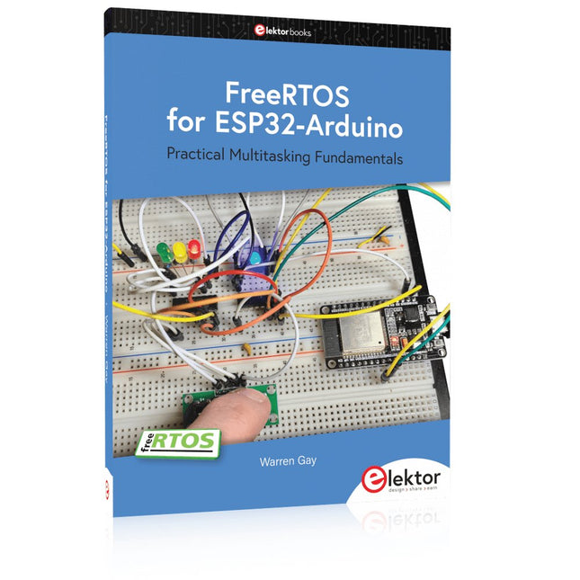
Elektor Publishing FreeRTOS for ESP32-Arduino
Practical Multitasking Fundamentals Programming embedded systems is difficult because of resource constraints and limited debugging facilities. Why develop your own Real-Time Operating System (RTOS) as well as your application when the proven FreeRTOS software is freely available? Why not start with a validated foundation? Every software developer knows that you must divide a difficult problem into smaller ones to conquer it. Using separate preemptive tasks and FreeRTOS communication mechanisms, a clean separation of functions is achieved within the entire application. This results in safe and maintainable designs. Practicing engineers and students alike can use this book and the ESP32 Arduino environment to wade into FreeRTOS concepts at a comfortable pace. The well-organized text enables you to master each concept before starting the next chapter. Practical breadboard experiments and schematics are included to bring the lessons home. Experience is the best teacher. Each chapter includes exercises to test your knowledge. The coverage of the FreeRTOS Application Programming Interface (API) is complete for the ESP32 Arduino environment. You can apply what you learn to other FreeRTOS environments, including Espressif’s ESP-IDF. The source code is available from GitHub. All of these resources put you in the driver’s seat when it is time to develop your next uber-cool ESP32 project. What you will learn: How preemptive scheduling works within FreeRTOS The Arduino startup “loopTask” Message queues FreeRTOS timers and the IDLE task The semaphore, mutex, and their differences The mailbox and its application Real-time task priorities and its effect Interrupt interaction and use with FreeRTOS Queue sets Notifying tasks with events Event groups Critical sections Task local storage The gatekeeper task
€ 49,95
Leden: € 44,96
-

Elektor Digital Elektor 03-04/2023 (PDF)
Diese Ausgabe steht allen GOLD- und GREEN-Mitgliedern auf der ElektorMagazine-Website zum Download bereit! Sie sind noch kein Mitglied? Hier klicken! Cloc 2.0Der Wecker, den Sie sich schon immer gewünscht haben Raspberry Pi Pico: PIO in der PraxisExperimente mit der Programmable I/O des RP2040 ChipTweaker des armen MannesBillige Wege, sie zum Sprechen zu bringen Echter Zufallszahlen-Generator mit USBZwei PICs zum Preis von einem AVR Pimp my mike...Pegelanhebung selbst gebaut FFT mit MaixduinoFrequenzspektren erfassen Aus dem Leben gegriffenEntwurfslogik (oder Un-Logik) Schrittmotor-Treiber UCN5804Bemerkenswerte Bauteile Schaltungssimulation mit Micro-CapErste Schritte in eine komplizierte Welt Der PAUL Award 2022Junge Techniktalente und ihre kreativen Lösungen Mein erstes Software-definiertes RadioGebaut in weniger als 15 Minuten Mikrocontroller-Dokumentation verstehenTeil 1: Aufbau einer Dokumentation KI und eingebettete Systeme - Was kommt als Nächstes?Werkzeuge, Plattformen und das Ende der Textarbeiter Digitalisierung der vertikalen Landwirtschaft Infografik: Embedded und KI, heute und morgen Einführung in TinyML Casestudy KwickPOS High-Performance in jeder KlasseComputer-on-Module-Standards Aller Anfang...muss nicht schwer sein: Werden wir aktiv! I²C-Kommunikation mit Node.js und einem Raspberry PiSehen Sie Ihre Sensordaten in einem Browser Videoausgabe mit MikrocontrollernTeil 2: VGA- und DVI-Ausgabe Das Echtzeit-Betriebssystem MetronomEin RTOS für AVR-Prozessoren DVI auf dem RP2040Ein Interview mit Luke Wren, Chip-Entwickler bei Raspberry Pi Display HAT MiniZeigt die Wettervorhersage auf dem Raspberry Pi WEEF 2022 Awards: Feiern Sie das Gute! Hexadoku
€ 11,90
-

Elektor Labs Elektor Arduino Nano MCCAB Training Board
Het Elektor Arduino Nano MCCAB Training Board bevat alle componenten (incl. Arduino Nano) die nodig zijn voor de oefeningen, zoals LED’s, schakelaars, drukknoppen, buzzer enz. Ook externe sensoren, motoren of modules kunnen worden gecheckt of bestuurd met dit microcontroller-trainingssysteem. Specificaties (Arduino Nano Training Board MCCAB) Voeding Via de USB-aansluiting van de aangesloten pc of een externe voeding (niet inbegrepen) Spanning +5 Vcc Ingangsspanning Alle ingangen 0 V tot +5 V VX1 en VX2 +8 V tot +12 V (alleen bij gebruik van een externe voeding) Hardware LCD 2x16 karakters Potentiometer P1 & P2 JP3: Selectie van de werkspanning van P1 & P2 Verdelers SV4: Verdeler voor de werkspanningenSV5, SV6: Verdelers voor de in-/uitgangen van de microcontroller Schakelaars en knoppen RESET knop op de Arduino Nano module; 6x drukknop schakelaars K1 ... K6; 6x Schuifschakelaars S1 ... S6; JP2: Jumper van de schakelaars met de ingangen van de microcontroller Buzzer Piezo buzzer ‘Buzzer1’ met jumper op JP6 Indicator LED’s 11 x LED: Status indicator voor de ingangen/uitgangen LED L op de Arduino Nano module, aangesloten op GPIO D13 JP6; Aansluiting van LED's LD10 ... LD20 met GPIO's D2 ... D12 Seriële interfacesSPI & I²C JP4: Selectie van het signaal op pin X van de SPI-connector SV12 SV9 naar SV12: SPI-interface (3,3 V/5 V) of I²C-interface Uitgangen voor externe apparaten SV1, SV7: Geschakelde uitgang (maximaal +24 V/160 mA, extern aangesloten) SV2: 2x13 pinnen voor aansluiting van externe modules 3x3 LED matrix(9 rode LED's) SV3: Kolommen van de 3x3 LED matrix (uitgangen D6 ... D8) JP1: Verbinding van de rijen met de GPIO's D3 ... D5 Software MCCABLib library Controle van hardware componenten (schakelaars, knoppen, LED's, 3x3 LED matrix, buzzer) op het MCCAB Training Board Werktemperatuur Tot +40 °C Afmetingen 100 x 100 x 20 mm Specificaties (Arduino Nano) Microcontroller ATmega328P Architectuur AVR Spanning 5 V Flash memory 32 KB, waarvan 2 KB gebruikt door de bootloader SRAM 2 KB Kloksnelheid 16 MHz Analoge IN Pinnen 8 EEPROM 1 KB DC stroom per I/O-pin 40 mA op één I/O-pin, totaal maximaal 200 mA op alle pinnen samen Ingangsspanning 7-12 V Digitale I/O-pinnen 22 (waarvan 6 PWM) PWM Uitgangen 6 Stroomverbruik 19 mA Afmetingen 18 x 45 mm Gewicht 7 g Inbegrepen 1x Elektor Arduino Nano Training Board MCCAB 1x Arduino Nano
€ 79,95€ 69,95Beste prijs
-
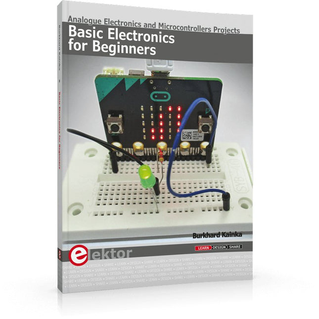
Elektor Publishing Basic Electronics for Beginners
Analogue Electronics and Microcontrollers Projects Hobbyist electronics can be a fun way to learn new skills that can be helpful to your career. Those who understand the basics of electronics can design their own circuits and projects. However, before you run, you need to learn to walk. It all starts with analogue electronics. You should be familiar with the simple components and circuits and understand their basic behaviors and the issues you may encounter. The best way to do this is through real experiments. Theory alone is not enough. This book offers a large number of practical entry-level circuits, with which everyone can gain the basic experience. Through the widespread introduction of microcontrollers, a new chapter in electronics has begun. Microcontrollers are now performing more and more tasks that were originally solved using discrete components and conventional ICs. Starting out has become easier and easier thanks to platforms including Bascom, Arduino, micro:bit. The book introduces numerous manageable microcontroller applications. It’s now a case of less soldering and more programming.
€ 39,95
Leden: € 35,96
-

Édition spéciale : Les capteurs météorologiques et environnementaux
Construisez votre station météo idéale ou explorez les données environnementales avec le monde entier. Avec de nombreux projets pratiques pour Arduino, Raspberry Pi, NodeMCU, ESP32 et autres cartes de développement. Les stations météo jouissent d’une grande popularité depuis des décennies. Tous les magazines d’électronique, qu’ils soient récents ou non, ont publié et publient régulièrement des articles sur la construction d’une station météo. Au fil des années, elles sont devenues de plus en plus sophistiquées et peuvent aujourd’hui être entièrement intégrées dans la maison intelligente. Ceci implique toutefois souvent une fidélité à un fabricant de produits de marque (coûteux) pour tous les composants. Cependant, avec votre propre station météo, vous pouvez facilement suivre le rythme et même capturer des relevés que les appareils commerciaux ne peuvent pas réaliser. Le plaisir ne manque pas : vous développerez de manière ludique vos connaissances en électronique, en cartes de développement de microcontrôleurs modernes et en langages de programmation. Pour moins de dix euros, vous pouvez collecter des données environnementales initiales et étendre votre système au fur et à mesure que votre intérêt grandit. Dans ce numéro Sur la route du vent et de la météo Écran météo OpenWeatherMap à affichage fluorescent Les composés organiques volatils dans l‘air que nous respirons Travailler avec les capteurs MQ : mesurer le monoxyde de carbone Détecteur de CO2 avec connexion IdO vers ThingSpeak Un arrosage automatique pour vos plantes Un climat intérieur sain : la température et l‘humidité de l‘air sont importants Thermomètre avec tubes Nixie Une maison météo rétro pour toute la famille Mesurez la pression atmosphérique et la température avec précision Un détecteur de coups de soleil Capteur maison pour la durée d‘ensoleillement Le smartphone l‘indique : brouillard ou bonne visibilité ? Détecter les tremblements de terre Les niveaux des cours d‘eau et des réservoirs Évaluer la valeur du pH de l’eau Détecter les rayonnements radioactifs Avec le GPS, vous savez où se trouve votre capteur Enregistrer les fichiers journaux avec horodatage sur des cartes SD LoRaWAN, The Things Network et ThingSpeak Exploiter la passerelle LoRaWAN pour le TTN Affichage géant à led avec prévisions météo
€ 15,50
Leden: € 13,95


