
Zoekresultaten voor "USB OR serial OR hub"
-
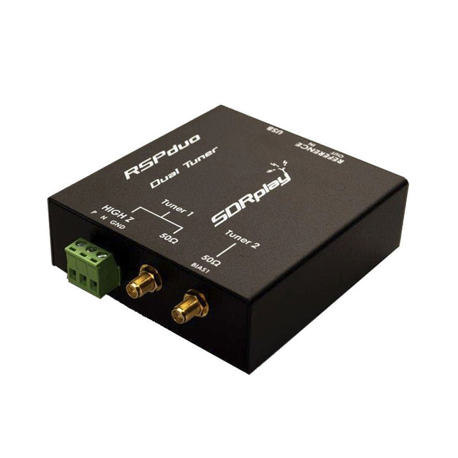
SDRplay SDRplay RSPduo Dual-Tuner 14-bit SDR-ontvanger (1 kHz tot 2 GHz)
De SDRplay RSPduo is een hoogwaardige 14-bit SDR-ontvanger met dubbele tuner. De tuner is ondergebracht in een hoogwaardige stalen behuizing en kan afzonderlijk werken tussen 1 kHz en 2 GHz met een bandbreedte tot 10 MHz. Beide tuners kunnen tegelijkertijd werken tussen 1 kHz en 2 GHz met een bandbreedte tot 2 MHz per tuner. Een zeer stabiele referentie en externe klokfuncties maken dit apparaat ideaal voor industriële, wetenschappelijke en educatieve toepassingen. Kenmerken Dubbele tuner biedt onafhankelijke dekking van 1 kHz tot 2 GHz met behulp van 2 antennepoorten tegelijk 14-bits ADC-siliciumtechnologie Tot 10 MHz zichtbare bandbreedte (enkele tunermodus) of 2 slices van 2 MHz spectrum (dubbele tunermodus) 3 softwarematig selecteerbare antennepoorten (2x 50Ω en 1x 1kΩ hoge impedantie gebalanceerde/ongebalanceerde ingang) Antennepoort met hoge impedantie (1 kHz tot 30 MHz) met selecteerbaar MW-notchfilter en keuze uit 2 voorselectiefilters Softwarematig selecteerbare AM/FM- en DAB-uitzendband-notchfilters voor de 2 SMA-antennepoorten (1 kHz tot 2 GHz) Externe klokinvoer en -uitvoer maken eenvoudige synchronisatie met meerdere RSP's of een externe referentieklok mogelijk Wordt gevoed via de USB-kabel met een eenvoudige type B-aansluiting 11 hoogselectieve, ingebouwde front-end preselectiefilters op beide 2 SMA-antennepoorten Softwarematig selecteerbare multi-level Low Noise voorversterker Bias-T voeding voor het voeden van een op de antenne gemonteerde LNA In een robuuste, zwart gelakte stalen behuizing. SDRuno – SDR-software van wereldklasse voor Windows Gedocumenteerde API voor de ontwikkeling van nieuwe apps Specificaties Frequentiebereik 1 kHz – 2 GHz Antenne-aansluiting SMA Antenne-impedantie 50 ohm Stroomverbruik (typisch) Enkele tunermodus: 180 mA (excl. Bias-T)Dubbele tunermodus: 280 mA (excl. Bias-T) USB-aansluiting USB type B Maximaal ingangsvermogen +0 dBm Continu+10 dBm korte duur ADC-samplefrequenties 2-10,66 MSPS ADC-aantal bits 14 bit 2-6,048 MSPS12 bit 6,048-8,064 MSPS10 bit 8,064-9,216 MSPS8 bit >9,216 MSPS Bias-T 4,7 V100 mA gegarandeerd Referentie Hoge temperatuurstabiliteit (0,5 ppm) 24 MHz TCXOFrequentiefout instelbaar tot 0,01 ppm in het veld Bedrijfstemperatuurbereik −10°C tot +60°C Afmetingen 98 x 94 x 33 mm Gewicht 315 g Downloads Datasheet Detailed Technical Information Software RSPdx-R2 vs RSPduo RSPdx-R2 RSPduo Continue dekking van 1 kHz tot 2 GHz ✓ ✓ Tot 10 MHz zichtbare bandbreedte ✓ ✓ 14-bits ADC siliciumtechnologie plus meerdere krachtige ingangsfilters ✓ ✓ Softwarematig selecteerbare AM/FM & DAB broadcast band notch filters ✓ ✓ 4,7 V Bias-T voor voeding van externe antenneversterker ✓ ✓ Voedt de USB-kabel met een eenvoudige aansluiting type B ✓ ✓ 50Ω SMA-antenne-ingang(en) voor werking van 1 kHz tot 2 GHz (softwarematig instelbaar) 2 2 Extra softwarematig selecteerbare Hi-Z ingang voor werking tot 30 MHz ✓ Extra softwarematig selecteerbare 50Ω BNC-ingang voor werking tot 200 MHz ✓ Extra LF/VLF-filter voor onder 500 kHz ✓ 24 MHz referentieklokingang (+ uitgang op RSPduo) ✓ ✓ Dubbele tuners voor ontvangst op 2 totaal onafhankelijke 2 MHz-bereiken ✓ Dubbele tuners voor diversiteitsontvangst met SDRuno ✓ Robuuste zwartgelakte stalen behuizing ✓ ✓ Algemene prestaties onder 2 MHz voor MW en LF ++ + Meerdere gelijktijdige toepassingen + ++ Prestaties in uitdagende fading-omstandigheden (*met gebruik van diversiteitsafstemming) + *++
€ 287,98
-

Clearpath Robotics Clearpath Robotics TurtleBot 4 Lite
TurtleBot 4 is the next-generation of the world’s most popular open source robotics platform for education and research, offering better computing power, better sensors and a world class user experience at an affordable price point.TurtleBot 4 Lite is equipped with an iRobot Create 3 mobile base, a powerful Raspberry Pi 4 running ROS 2, OAK-D spatial AI stereo camera, 2D LiDAR and more. All components have been seamlessly integrated to deliver an out-of-the-box development and learning platform.Specifications Base platform iRobot Create 3 Wheels (Diameter) 72 mm Ground Clearance 4.5 mm On-board Computer Raspberry Pi 4 (4 GB) Maximum linear velocity 0.31 m/s in safe mode0.46 m/s without safe mode Maximum angular velocity 1.90 rad/s Maximum payload 9 kg Operation time 2h 30m – 4h depending on load Charging time 2h 30m Lidar RPLIDAR A1M8 Camera OAK-D-Lite User Power VBAT @1.9 A5 V @ Low current3.3 V @ Low current USB Expansion 2x USB 2.0 (Type A)2x USB 3.0 (Type A) Programmable LEDs Create 3 Lightring Buttons and Switches 2x Create 3 User buttons1x Create 3 Power Button Battery 26 Wh Lithium Ion (14.4 V nominal) Charging Dock Included Size (L x W x H) 342 x 339 x 192 mm Weight 3.3 kg DownloadsUser Manual
€ 1.699,00
Beste prijs
-

Elektor Circuit Special 2025 (EN)
Elektor GREEN and GOLD members can download their digital edition here. Not a member yet? Click here. USB Measurement AdapterTesting Current and Signal Quality of USB Ports 4...20 mA Current Output for Arduino UnoA Reliable, EMI-Insensitive Current Loop Interface Vacuum Cleaner Automatic ControlKeep Your Tools’ Work Area Clean DDS Generator with ATtiny Opamp-Tester V2New PCB – Now Also Suitable for SMDs 550-mW “Lamp” Audio AmplifierGet the Warm Sound of Vacuum Tubes With Ease Fuse GuardMonitoring a Fuse with a Flashing LED HQ RIAA PreamplifierGet the Most Out of Your Vinyl Records! Turntable Speed CalibratorAn Arduino-Based 100–120 Hz Strobe Light Generator Elektor Classics: video buffer/repeater Infrared Remote-Controlled DimmerControl Your Halogen or LED Floor Lamp Effortlessly and With Style How to Use switch…case on Strings in C++/Arduino IDE Magnet FinderWith a Simple Hall-Effect Sensor Raspberry Pi Smart Power ButtonA Solution for Raspberry Pi Up to Model 4 Essential Maker TipsProfessional Insights for Everyday Making Practical Projects with the 555 TimerDC Motor Control and Fast Reaction Challenges Basic AC-Load-On MonitorSave Energy with a Simple Device Power Banks in ParallelA Three-Day Continuous Power Solution VFO Up to 15 MHzAn Implementation With Raspberry Pi Pico Violin Tuner with ATtiny202 Elektor Classics: video amplifier for B/W television sets Capacitance Meter20 pF to 600 nF Quasi-Analog Clockwork Mk IITwo LED Rings for Hours and Minutes You Can Do Anything You Want(with the Arduino Ecosystem at Your Side) Neon Lamp Dice Elektor Classics: RTTY calibrator indicator Inspiring Hardware Designs for Your ESPs Elektor Classics: variable 3 A power supply RGB LEDs with Integrated Control CircuitLight with Precision: ICLEDs Set Standards Experiment: Towards a Mixed-Signal Theremin?Blending Modern Time-of-Flight Sensors With the Timeless XR2206 Analog Generator ESP32 Audio Transceiver Board (Part 1)SD Card WAV File Player Demo Infographics: Circuits and Circuit Design 2025 Small Audio MixerA Simple and Versatile Scalable Design Smart Staircase Light TimerSave More Money on the Energy Bill! Smarten Up Your ShuttersControlling Velux Hardware With an ESP32 and MQTT Solid-State Foot WarmerEnergy-Efficient Comfort Is the M5Stamp Fly Quadcopter the Next Tello? Boosting Wi-Fi Range of the ESP32-C3 SuperMiniA Simple and Effective Antenna Mod ZD-8968 Hot-Air Soldering StationA Budget-Friendly Workhorse or Just Hot Air? Parking Sensor TesterFinding Defects in the PDC System of a Car
€ 14,90
-

Siglent Siglent SDS1104X-E 4-kanaals Oscilloscoop (100 MHz)
The Siglent SDS1104X-E employs a new generation of SPO (Super Phosphor Oscilloscope) technology that provides excellent signal fidelity and performance. The system noise is also lower than similar products in the industry. It comes with a minimum vertical input range of 500 uV/div, an innovative digital trigger system with high sensitivity and low jitter, and a waveform capture rate of 400,000 frames/ sec (sequence mode). The SDS1104X-E also employs a 256-level intensity grading display function and a color temperature display mode not found in other models in this class. SIGLENT’s latest oscilloscopes offering supports multiple powerful triggering modes including serial bus triggering. Serial decoding is free and includes IIC, SPI, UART, CAN, and LIN. History waveform recording and sequential triggering enable extended waveform recording and analysis. Another powerful addition is the new 1 Mpt FFT math function that gives the SDS1104X-E very high frequency resolution when observing signal spectra. Kenmerken Intelligent trigger: Edge, Slope, Pulse Width, Window, Runt, Interval, Timeout (Dropout), and Pattern Free Serial bus triggering and decoding:IIC, SPI, UART, RS232, CAN, and LIN Video triggers and supports HDTV Low background noise and 500 ?V / div to 10 V / div voltage scales 10 types of one-button shortcuts, supports Auto Setup, Default, Cursors, Measure, Roll, History, Display/Persist, Clear Sweep, Zoom and Print Segmented acquisition (Sequence) mode, dividing the maximum record length into multiple segments (up to 80,000), according to trigger conditions set by the user, with a very small dead time segment to capture the qualifying event. History waveform record (History) function, the maximum recorded waveform length is 80,000 frames Automatic measurement function on 38 parameters, supports Statistics, Gating measurement, Math measurement, History measurement and Ref measurement 1 Mpts FFT True measurement and math can use all 14 Mpts of memory Preset key can be customized for user settings or factory “defaults” Security Erase mode Highspeed hardware based Pass/ Fail function Large 7-inch TFT-LCD display with 800 * 480 resolution Multiple interface types: USB Host, USB Device (USB-TMC), LAN (VXI-11), Pass / Fail, Trigger Out Supports SCPI remote control commands Multi-language display and embedded help Browser control/onboard webpage for software free monitoring (4 channel models only) Inbegrepen 1x Siglent SDS1104X-E Oscilloscope 4x 100 MHz probes 1x Guarantee Card 1x Power Cord 1x USB Cable 1x Quick Start Guide Downloads Datasheet Manual Programming Guide
€ 508,71
-

Andonstar Andonstar AD407 Pro 7" HDMI Digitale Microscoop
De Andonstar AD407 Pro microscoop is geschikt voor diverse toepassingen, zoals het solderen van SMD's, of bij reparaties. De microscoop heeft een groot verstelbaar 7" LCD-scherm en wordt geleverd met een afstandsbediening. In vergelijking met de AD407 biedt de AD407 Pro een extra hoge standaard, wat het solderen van componenten nóg eenvoudiger maakt. Specificaties Schermgrootte 7 inch (17,8 cm) Beeldsensor 4 MP Video uitgang UHD 2880x2160 (24 fps)FHD 1920x1080 (60 fps/30 fps)HD 1280x720 (120 fps) Video formaat MP4 Vergroting Tot 270 keer (27 inch HDMI-monitor) Foto resolutie Max. 12 MP (4032x3024) Foto formaat JPG Focus afstand Min. 5 cm Frame rate Max. 120fps Video interface HDMI Opslag MicroSD-kaart (tot 64 GB) Voeding 5 V DC Verlichting 2 LED’s op de standaard Afmetingen standaard 20 x 18 x 32 cm Inbegrepen 1x Andonstar AD407 Pro Digital Microscope 1x Metalen standaard met 2 LED's 1x UV-filter (reeds gemonteerd in de lens) 1x IR-afstandsbediening 1x Switch kabel 1x Voedingsadapter 1x Instelsleutel 2x Metalen clips 1x HDMI-kabel 1x Manual Downloads Manual Vergelijking modellen AD407 AD407 Pro AD409 AD409 Pro-ES Schermgrootte 7 inch (17,8 cm) 7 inch (17,8 cm) 10,1 inch (25,7 cm) 10,1 inch (25,7 cm) Beeldsensor 4 MP 4 MP 4 MP 4 MP Video uitgang 2160p 2160p 2160p 2160p Interfaces HDMI HDMI USB, HDMI, WiFi USB, HDMI, WiFi Video formaat MP4 MP4 MP4 MP4 Vergroting Tot 270x Tot 270x Tot 300x Tot 300x Foto resolutie Max. 4032x3024 Max. 4032x3024 Max. 4032x3024 Max. 4032x3024 Foto formaat JPG JPG JPG JPG Focus afstand Min. 5 cm Min. 5 cm Min. 5 cm Min. 5 cm Frame rate Max. 120f/s Max. 120f/s Max. 120f/s Max. 120f/s Opslag MicroSD-kaart MicroSD-kaart MicroSD-kaart MicroSD-kaart PC-ondersteuning Nee Nee Windows Windows Ondersteuning mobiel Nee Nee WiFi + Metingen WiFi + Metingen Voeding 5 V DC 5 V DC 5 V DC 5 V DC Verlichting 2 LED's op de standaard 2 LED's op de standaard 2 LED's op de standaard 2 LED's op de standaard Endoscoop Nee Nee Nee Ja Afmetingen standaard 20 x 12 x 19 cm 20 x 18 x 32 cm 18 x 20 x 30 cm 18 x 20 x 32 cm Gewicht 1,6 kg 2,1 kg 2,2 kg 2,5 kg
€ 226,27
-

Elektor Publishing MicroPython for STM32
Learning Embedded Systems with STM32 Nucleo Boards Programming compact electronic systems is now easier to get started with than ever before. Affordable development boards, powerful software tools, and readily available documentation make it possible to turn an idea into a working prototype in very little time. MicroPython plays an important role in this development by offering a readable, interactive way to control microcontrollers while still providing direct access to their hardware features. This book explores embedded programming with MicroPython using an STM32-based Nucleo board. It shows how a microcontroller continuously interacts with its environment by reading inputs, processing information, and controlling outputs. Step by step, you will learn to flash LEDs, measure analog signals, work with sensors, control actuators, and exchange data with other devices. The built-in REPL makes it easy to test instructions immediately, inspect results, and learn through experimentation. Although microcontroller boards differ in size, speed, memory, and peripherals, the fundamental concepts remain largely the same. Digital input and output, analog conversion, timers, PWM, interrupts, and serial communication are the essential building blocks of embedded applications. By concentrating on these transferable principles, the book provides a foundation that remains useful when moving to other boards, processors, or development environments. It is intended both for newcomers and for programmers who want to expand into embedded systems. MicroPython offers a practical route into this field, combining quick results with a clear understanding of how software and hardware work together.
€ 27,95
Leden: € 25,16
-
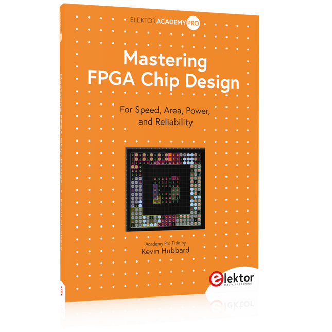
Elektor Publishing Mastering FPGA Chip Design
For Speed, Area, Power, and Reliability This book teaches the fundamentals of FPGA operation, covering basic CMOS transistor theory to designing digital FPGA chips using LUTs, flip-flops, and embedded memories. Ideal for electrical engineers aiming to design large digital chips using FPGA technology. Discover: The inner workings of FPGA architecture and functionality. Hardware Description Languages (HDL) like Verilog and VHDL. The EDA tool flow for converting HDL source into a functional FPGA chip design. Insider tips for reliable, low power, and high performance FPGA designs. Example designs include: Computer-to-FPGA UART serial communication. An open-source Sump3 logic analyzer implementation. A fully functional graphics controller. What you need: Digilent BASYS3 or similar FPGA eval board with an AMD/Xilinx FPGA. Vivado EDA tool suite (available for download from AMD website free of charge). Project source files available from author’s GitHub site.
€ 39,95
Leden: € 35,96
-

Elektor Digital Mastering the I²C Bus (E-book)
Mastering the I²C Bus takes you on an exploratory journey of the I²C Bus and its applications. Besides the Bus protocol, plenty of attention is given to the practical applications and designing a stable system. The most common I²C compatible chip classes are covered in detail. Two experimentation boards are available that allow for rapid prototype development. These boards are completed by a USB to I²C probe and a software framework to control I²C devices from your computer. All samples programs can be downloaded from the 'Attachments/Downloads' section on this page. Projects built on Board 1: USB to I²C Interface, PCA 9534 Protected Input, PCA 9534 Protected Output, PCA 9553 PWM LED Controller, 24xxx EEPROM Module, LM75 Temperature Sensor, PCA8563 Real-time Clock with Battery Backup, LCD and Keyboard Module, Bus Power Supply. Projects built on Board 2: Protected Input, Protected Output, LM75 Temperature Sensor, PCF8574 I/O Board, SAA1064 LED Display, PCA9544 Bus Expander, MCP40D17 Potentiometer, PCF8591 AD/DA, ADC121 A/D Converter, MCP4725 D/A Converter, 24xxx EEPROM Module.
€ 34,95
Leden: € 31,46
-
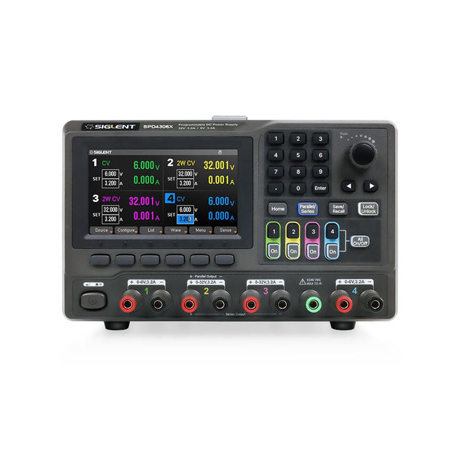
Siglent Siglent SPD4306X 4-kanaals Voeding (400 W)
The Siglent SPD4306X is a 4-channel DC Linear Programmable Power Supply equipped with a 4.3-inch TFT-LCD display, friendly human-machine interface, and excellent performance indicators. Real-time waveform display provides engineers with an informative user interface. SPD4306X offers a total output power of 400 W with a resolution of 1 mV/1 mA. The maximum voltage and current for each channel are as follows: CH1: 15 V/1.5 A CH2: 30 V/6 A CH3: 30 V/6 A CH4: 15 V/1 A Kenmerken Rated output power: 400 W Rated voltage: 32 V, 12 V, 30 V Up to four high-precision power supplies with independent controllable outputs, supporting CH2 and CH3 series and parallel connections Clear graphical interface with waveform and timer display modes 5-digit voltage and current display with minimum resolution of 1 mV, 1 mA Fast output response time: <50us The high current channel support remote voltage compensation sense function. The maximum compensation voltage is 0.6 V Overvoltage protection and overcurrent protection or safe and accurate operation Equipped with a 4.3-inch TFT-LCD display (480 x 272 resolution) USB and LAN standard communication USB-GPIB module is optional Excellent channel density with up to 4 channels in a 3U half rack package Internal data storage for setups and parameters Embedded Web Server with instrument communication that doesn’t require software installation Fully SCPI programming command set support as well as a LabView driver for remote control and system automation Specificaties SPD4323X SPD4121X SPD4306X Channel Output CH1: Voltage 0 to 6 V Current 0 to 3.2 ACH2: Voltage 0 to 32 V Current 0 to 3.2 ACH3: Voltage 0 to 32 V Current 0 to 3.2 ACH4: Voltage 0 to 6 V Current 0 to 3.2 A CH1: Voltage 0 to 15 V Current 0 to 1.5 ACH2: Voltage 0 to 12 V Current 0 to 10 ACH3: Voltage 0 to 12 V Current 0 to 10 ACH4: Voltage 0 to 15 V Current 0 to 1.5 A CH1: Voltage 0 to 15 V Current 0 to 1.5 ACH2: Voltage 0 to 30 V Current 0 to 6 ACH3: Voltage 0 to 30 V Current 0 to 6 ACH4: Voltage 0 to 15 V Current 0 to 1 A Resolution 1 mV, 1 mA 1 mV, 1 mA 1 mV, 1 mA Setting Accuracy Voltage: ±(0.03% of reading+10) mV, Current: ±(0.3% of reading+10) mA Voltage: ±(0.03% of reading+10) mV, Current: ±(0.3% of reading+10) mA Voltage: ±(0.03% of reading+10) mV, Current: ±(0.3% of reading+10) mA Readback Accuracy Voltage: ±(0.03% of reading+10) mV, Current: ±(0.3% of reading+10) mA Voltage: ±(0.03% of reading+10) mV, Current: ±(0.3% of reading+10) mA Voltage: ±(0.03% of reading+10) mV, Current: ±(0.3% of reading+10) mA Display 4.3" TFT-LCD 5-digit voltage and current display 4.3" TFT-LCD 5-digit voltage and current display 4.3" TFT-LCD 5-digit voltage and current display Output power 240 W 285 W 400 W Inbegrepen 1x Siglent SPD4306X Power Supply 1x Power cord (EU) 1x Output test cord (3 A) 1x USB cable 1x Quick start guide Downloads Datasheet Manual Quick start
€ 1.101,10
-

Rigol Rigol DG2072 Function/Arbitrary Waveform Generator (70 MHz)
Highlights Output Frequency (Sine): 70 MHz Output Frequency (Square): 20 MHz Channels: 2 Arbitrary Waveform Length: 16 Mpts Kenmerken Unique SiFi II (Signal Fidelity II) technology: generate the arbitrary waveforms point by point; recover the signal without distortion; sample rate accurate and adjustable; jitter of all the output waveforms (including Sine, Pulse, etc.) as low as 200 ps 16 Mpts memory depth per channel for arbitrary waveforms Standard dual-channel with the same performance, equivalent to two independent signal sources High frequency stability: ±1 ppm; low phase noise: -105 dBc/Hz Built-in high-order harmonic generator (at most 8-order harmonics) Built-in 7 digits/s, 240 MHz bandwidth full featured frequency counter Up to 160 built-in arbitrary waveforms, covering the common signals in engineering application, medical electronics, auto electronics, math processing, and other various fields Sample rate up to 250 MSa/s, vertical resolution 16 bits Arbitrary waveform sequence editing function available; arbitrary waveforms also can be generated through the PC software Various analog and digital modulation functions: AM, FM, PM, ASK, FSK, PSK, and PWM. Standard waveform combine function, capable of outputting specified waveforms combined with the basic waveforms Standard channel tracking function, when enabled, all the parameters of both channels are updated based on users' configurations Standard interface: USB Host&Device and LAN (LXI Core 2011 Device); USB-GPIB function supported 4.3'' TFT Inbegrepen 1x Rigol DG2072 Function/Arbitrary Waveform Generator 1x Power cord 1x USB cable
€ 882,09
-

Elektor Digital Visual Basic für Elektroniksteuerungen und Entwicklung (E-book)
Der PC wird schon lange nicht mehr nur als einfacher Computer verwendet, sondern hat sich zu einem Universalwerkzeug entwickelt. Dieses Buch richtet sich an diejenigen, die vorhandene oder selbstgebaute Hardware über den Computer steuern wollen. Der Einsatz von Visual Basic für die schnelle Entwicklung von Elektronikapplikationen öffnet Ihnen eine Welt, die über die Anschlüsse des PCs hinausreicht. Sobald Sie sich mit Visual Basic, seiner Entwicklungsumgebung und den angebotenen Toolsets vertraut gemacht haben, werden Dinge wie die serielle Kommunikation, Druckerports, Bitbanging, Protokoll-Emulation, die ISA-, USB- und Ethernet-Schnittstellen und die Fernsteuerung von Mess- und Testaufbauten über den GPIB-Bus in allen Einzelheiten behandelt. Zu jedem Punkt gibt es einen übersichtlichen und lauffähigen Programmcode und wo nötig existieren Schaltpläne, mit denen Sie Ihr Projekt in kurzer Zeit einsatzfähig machen können. Darüber hinausgehend erläutert dieses Buch den Umgang mit Debug-Tools bei der Suche nach Hardware-Adressen, den Aufbau einer Verbindung über TCP/IP- und UDP-Sockets und Sie lernen sogar eigene Internetserver zu programmieren. Oder wollen Sie Ihre Hardware über USB oder Ethernet anbinden und mit Visual Basic steuern? Auch die Kommunikation zwischen Programmen, DDE und das neue Grafik-Interface von Windows XP werden behandelt. Alle Programmbeispiele lassen sich mit Visual Basic 5.0, 6.0, .NET oder 2005 kompilieren. Auch die Unterschiede zwischen Visual Basic Classic und Visual Basic NET/2005 sind ausführlich erläutert.
€ 39,80
Leden: € 35,82
-
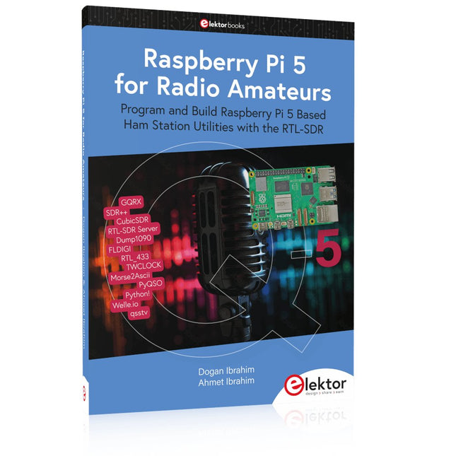
Elektor Publishing Raspberry Pi 5 for Radio Amateurs
Program and Build Raspberry Pi 5 Based Ham Station Utilities with the RTL-SDR The RTL-SDR devices (V3 and V4) have gained popularity among radio amateurs because of their very low cost and rich features. A basic system may consist of a USB based RTL-SDR device (dongle) with a suitable antenna, a Raspberry Pi 5 computer, a USB based external audio input-output adapter, and software installed on the Raspberry Pi 5 computer. With such a modest setup, it is possible to receive signals from around 24 MHz to over 1.7 GHz. This book is aimed at amateur radio enthusiasts and electronic engineering students, as well as at anyone interested in learning to use the Raspberry Pi 5 to build electronic projects. The book is suitable for both beginners through experienced readers. Some knowledge of the Python programming language is required to understand and eventually modify the projects given in the book. A block diagram, a circuit diagram, and a complete Python program listing is given for each project, alongside a comprehensive description. The following popular RTL-SDR programs are discussed in detail, aided by step-by-step installation guides for practical use on a Raspberry Pi 5: SimpleFM GQRX SDR++ CubicSDR RTL-SDR Server Dump1090 FLDIGI Quick RTL_433 aldo xcwcp GPredict TWCLOCK CQRLOG klog Morse2Ascii PyQSO Welle.io Ham Clock CHIRP xastir qsstv flrig XyGrib FreeDV Qtel (EchoLink) XDX (DX-Cluster) WSJT-X The application of the Python programming language on the latest Raspberry Pi 5 platform precludes the use of the programs in the book from working on older versions of Raspberry Pi computers.
€ 39,95
Leden: € 35,96


