De OWON SDS1102 is een betaalbare benchtop digitale oscilloscoop die solide prestaties combineert met essentiële meetfuncties. Deze 2-kanaals oscilloscoop biedt een bandbreedte van 100 MHz, een sample rate van 1 GS/s, een 7-inch LCD-display en een geheugendiepte van 10 kpts. Daarmee is het een praktische keuze voor dagelijkse elektronicatests, foutopsporing en onderwijs.
De SDS1102 beschikt over een vereenvoudigd triggersysteem met niveau- en flanktriggering, waardoor gangbare signalen eenvoudig kunnen worden vastgelegd en geanalyseerd. Het apparaat is ontworpen voor toepassingen waarvoor geen grote geheugendiepte of geavanceerde triggerfuncties nodig zijn, en biedt een eenvoudige en kostenefficiënte oplossing voor basis-signaalanalyse.
Kenmerken
Bandbreedte: 100 MHz
2 kanalen
Bemonsteringssnelheid: 1 GS/s
Ultradunne behuizing
7-inch lcd met hoge resolutie
Ondersteuning voor SCPI en LabVIEW
Specificaties
Bandbreedte
100 MHz
Horizontale schaal (s/div)
5 ns/div - 1000 s/div
Kanalen
2
Verticale gevoeligheid
5 mV/div - 5 V/div (bij ingang)
DC Gain nauwkeurigheid
3%
Verticale resolutie (A/D)
8 bits (2 kanalen tegelijk)
Ingang
Ingangsimpedantie
1 MΩ, 10 pF
Ingangskoppeling
AC, DC, GND
Max ingangsspanning
± 400 V, CATI, CATII
Passieve probes
x1; 10
Probe verzwakkingsfactor
x1; x10; x100; x1000
Triggersysteem
Trigger mode
Auto, Normal, Single
Trigger type
Flank, Video
Flank triggerbron
CH1, CH2
Video trigger
Sampletype
Real-time
Samplefrequentie
1 GS/s
Equivalente samplesnelheid
No
Golflengte
10K pts
Interpolatie
sin(x)/x
Meet- en rekenkundig bewerkingssysteem
Automatische meting
Vpp, Vavg, RMS, Frequency, Period, Vmax, Vmin, Vtop, Vbase, Width, Overshoot, Pre-shoot Rise time, Fall time, +Width, -Width, +Duty, -Duty, Delay A->B, Delay A->B, area, cycle area
Rekenkundige functies
Addition, Subtraction, Multiplication, Division, FFT
Algemene kenmerken
Display maat
7" color LCD
Display resolutie
800 x 480
Voeding
100-240 V, 45-440 Hz, <15 W
Afmetingen
301 x 70 x 152 mm
Gewicht
1,1 kg
Inbegrepen
1x OWON SDS1102 Oscilloscoop
2x Oscilloscoopsonde
1x Sonde aanpassen
1x Netsnoer
1x USB-kabel
1x CD-Rom
1x Snelstartgids
Downloads
Quick Guide
Manual
PC Software
SCPI Commands
Get Cracking with the Arduino Nano V3, Nano Every, and Nano 33 IoT
The seven chapters in this book serve as the first step for novices and microcontroller enthusiasts wishing to make a head start in Arduino programming. The first chapter introduces the Arduino platform, ecosystem, and existing varieties of Arduino Nano boards. It also teaches how to install various tools needed to get started with Arduino Programming. The second chapter kicks off with electronic circuit building and programming around your Arduino. The third chapter explores various buses and analog inputs. In the fourth chapter, you get acquainted with the concept of pulse width modulation (PWM) and working with unipolar stepper motors.
In the fifth chapter, you are sure to learn about creating beautiful graphics and basic but useful animation with the aid of an external display. The sixth chapter introduces the readers to the concept of I/O devices such as sensors and the piezo buzzer, exploring their methods of interfacing and programming with the Arduino Nano. The last chapter explores another member of Arduino Nano family, Arduino Nano 33 IoT with its highly interesting capabilities. This chapter employs and deepens many concepts learned from previous chapters to create interesting applications for the vast world of the Internet of Things.
The entire book follows a step-by-step approach to explain concepts and the operation of things. Each concept is invariably followed by a to-the-point circuit diagram and code examples. Next come detailed explanations of the syntax and the logic used. By closely following the concepts, you will become comfortable with circuit building, Arduino programming, the workings of the code examples, and the circuit diagrams presented. The book also has plenty of references to external resources wherever needed.
An archive file (.zip) comprising the software examples and Fritzing-style circuit diagrams discussed in the book may be downloaded free of charge below.
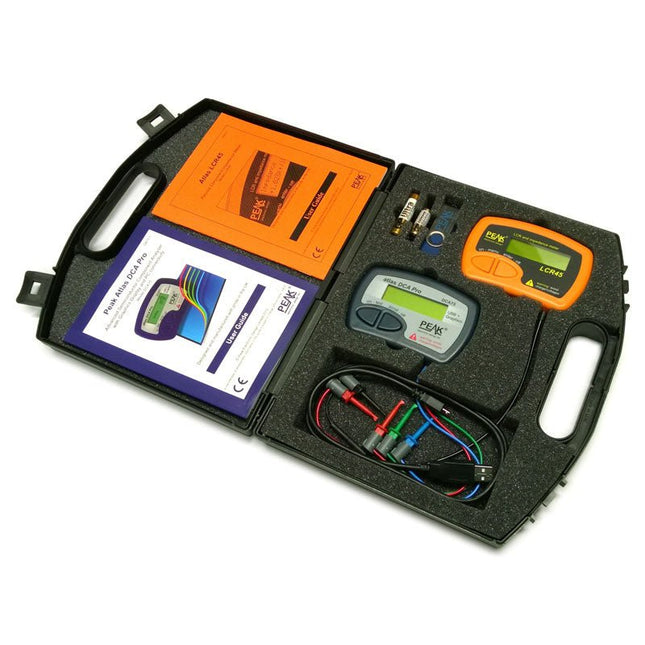
This pack contains the LCR45 Passive Component Impedance Meter, great for advanced hobbyists and professionals. It also contains the very popular DCA Pro (model DCA75), fantastic for component identification, pinout identification, detailed characteristic measurement and curve tracing on a PC. Complete with USB cable and software on a USB flash drive.
DCA75
Building on the continued success of Peak's existing component identification and analysis instruments, the DCA Pro brings an array of exciting new features for the hobbyist and professional alike.
The DCA Pro is an advanced new design that features a graphics display, USB communications, PC Software and an enhanced component identification library.
Automatic component type identification
Automatic pinout identification (connect any way round)
The DCA Pro supports all the components that the popular Peak Atlas DCA55 supports, but adds plenty more. Components supported include:
Transistors (including Darlingtons), Silicon and Germanium types. Measures gain, Vbe and leakage
MOSFETs, enhancement mode and depletion mode types. Measure on-threshold (at 5 mA) and approx transconductance (for span of 3-5 mA)
JFETs, including normally off SiC types. Measures pinch-off voltage (at 1 uA) and approx transconductance (for span of 3-5 mA)
IGBTs (insulated gate bipolar transistors). Measures on-threshold (at 5 mA)
Diodes and Diode networks
LEDs and bicolour LEDs (2 lead and 3 lead types)
Zener Diodes with measurement of zener voltage up to 9 V at 5 mA
Voltage regulators (measures regulation voltage, drop-out voltage, quiescent current)
Triacs and Thyristors that require less than 10 mA of gate current and holding current
Stand-alone or with a PC
The instrument can be used stand-alone or connected to a PC. Either way, the DCA Pro will automatically identify the component type, identify the pinout and also measure a range of component parameters such as transistor gain, leakage, MOSFET and IGBT threshold voltages, pn characteristics and much more.
Curve Tracing
When connected to a PC using the supplied USB cable, a range of low current curve-tracing functions can be performed. Various graph types are available, with more to follow:
Bipolar transistor output characteristics, IC vs VCE
Bipolar transistor gain characteristics, HFE vs VCE
Bipolar transistor gain characteristics, HFE vs IC
MOSFET and IGBT output function, ID vs VDS
MOSFET and IGBT transfer function, ID vs VGS
JFET output function, ID vs VDS
JFET transfer function, ID vs VGS
Voltage regulator, VOUT vs VIN
Voltage regulator, IQ vs VIN.
PN junction I/V curves, forward and reverse options (for Zener diodes)
Curve tracing is performed using test parameters in the range of +/-12 V or +/-12 mA. All curve-tracing data can be instantly pasted into Excel for further graphing and analysis. PC Software is included with the DCA Pro on a Peak USB memory stick. Software designed for Windows 7 and higher (all 32 or 64 bit).
LCR45
A great handheld LCR analyser that can measure the value of your passive component (inductor, capacitor or resistor) and also measure the detailed impedance in a number of modes. The LCR45 offers enhanced measurement resolution (better than 0.1 uH!) whilst also giving you continuous fluid measurements. Additionally, the test frequencies of DC, 1 kHz, 15 kHz and 200 kHz can be set to automatic or manual modes. Supplied with removable gold plated hook probes, battery and user guide. Compatible with standard 2 mm test connectors. Not designed for in-circuit use.
Automatic or manual component type selection: Inductor, Capacitor or Resistor
Automatic or manual test frequency selection: DC, 1 kHz, 15 kHz and 200 kHz
Inductance from 0.1 uH to 10 H
Capacitance from 0.1 pF to 10,000 uF
Resistance from 0.1 Ohm to 2 MOhm
Inductance measurement also shows DC winding resistance
Display of "Component type and values", "Complex Impedance", "Magnitude/Phase" and "Admittance"
Test frequency displayed for all measurements
Typical accuracy of 1.5% for inductors and capacitors (see spec table for details)
Typical accuracy of 1% for resistors
Test lead complete with gold plated 2 mm plugs and sockets
Supplied with removable gold plated hook probes
Inbegrepen
LCR45
DCA75
Extra GP23 Battery
Extra AAA cell
Dual Carry Case
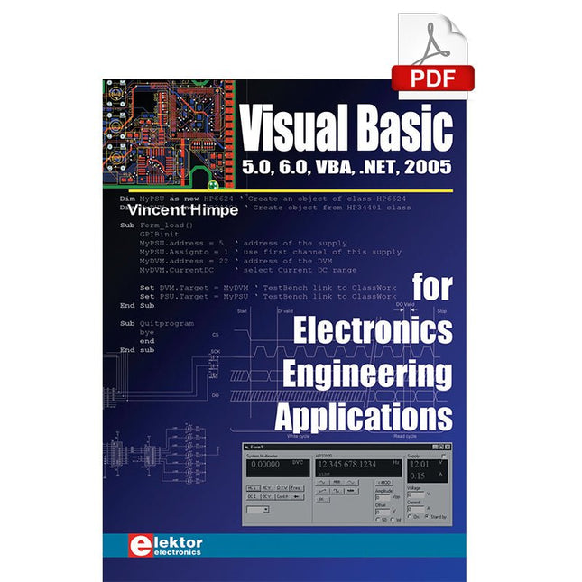
The PC has long-time outgrown its function as a pure computer and has become an all-purpose machine. This book is targeted towards those people that want to control existing or self-built hardware from their computer.
Using Visual Basic as Rapid Application Development tool we will take you on a journey to unlock the world beyond the connectors of the PC.
After familiarising yourself with Visual Basic, its development environment and the toolset it offers, items such as serial communications, printer ports, bit-banging, protocol emulation, ISA, USB and Ethernet interfacing and the remote control of test-equipment over the GPIB bus, are covered in extent. Each topic is accompanied by clear, ready to run code, and where necessary, schematics are provided that will get your projects up to speed in no time.
This book will show you advanced things like: using tools like Debug to find hardware addresses, setting up remote communication using TCP/IP and UDP sockets and even writing your own internet servers. Or how about connecting your own block of hardware over USB or Ethernet and controlling it from Visual Basic. Other things like internet-program communication, DDE and the new graphics interface of Windows XP are covered as well.
All examples are ready to compile using Visual Basic 5.0, 6.0, NET or 2005. Extensive coverage is given on the differences between what could be called Visual Basic Classic and Visual basic .NET / 2005.
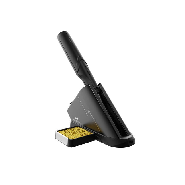
Het Miniware draadloze soldeerstation TS1C (met ingebouwd OLED-scherm en Bluetooth) is een intelligent soldeer tool dat in minder dan 20 seconden opwarmt tot 400°C. Dankzij de ingebouwde accu ligt de draadloze soldeerbout prettig in de hand en is hij gemakkelijk in gebruik.
Kenmerken
Nieuwe energieopslag technologie met hoogrenderende supercondensator, 10.000-level laad- en ontlaadtijden
Separaat ontwerp + true wireless, geniet daardoor van het draadloos solderen
BLE4.2 Bluetooth technologie voor het op afstand bedienen en instellen
Standaard PD2 20 V met 45 W max opgenomen vermogen, en tot 36 W soldeervermogen, kan continu meer dan 180 soldeerverbindingen (0805) solderen met één enkele volledige lading
Voorverwarming in het control station, om de verwarmingsefficiëntie te verbeteren
Drie uitbreidingssleuven voor accessoires
Control station
Standard PD2 20 V met 45 W max opgenomen vermogen, overstroom beveiliging
OLED-scherm met 128x64 pixels, weergave van de status van de soldeerbout in realtime
Voorverwarming in het control station, om de verwarmingsefficiëntie te verbeteren
Afstandsbediening en instelling: temperatuurregeling, menu instelling, weergave van informatie en status van het apparaat, enzovoort.
Functioneert als soldeerstandaard en laadstation
Drie uitbreidingssleuven voor meerdere aanvullende accessoires, zoals een sponssleuf
Soldeerbout
Ingebouwde 750F supercondensator voor energieopslag met hoog rendement, kan worden opgeladen via het control station (of in noodgevallen via de USB type-C-interface)
36 W maximaal verwarmingsvermogen, kan continu meer dan 180 soldeerverbindingen (0805) solderen met één enkele volledige lading
Compatibel met Miniware 3,5 mm audio-interface soldeerpunten (TS80/80P soldeerstift serie)
Boost modus (de knop op de pen ingedrukt houden)
Inbegrepen
TS1C Soldeerbout
TS1C Control Station
Soldeerstift (TS-B02)
Siliconen kabel
Sponsgleuf incl. spons
Handleiding
It is becoming important for microcontroller users to quickly learn and adapt to new technologies and architecture used in high performance 32-bit microcontrollers. Many manufacturers now offer 32-bit microcontrollers as general purpose processors in embedded applications.
ARM provide 32 and 64-bit processors mainly for embedded applications. These days, the majority of mobile devices including mobile phones, tablets, and GPS receivers are based on ARM technology. The low cost, low power consumption, and high performance of ARM processors makes them ideal for use in complex communication and mixed signal applications.
This book makes use of the ARM Cortex-M family of processors in easy-to-follow, practical projects. It gives a detailed introduction to the architecture of the Cortex-M family. Examples of popular hardware and software development kits are described.
The architecture of the highly popular ARM Cortex-M processor STM32F107VCT6 is described at a high level, taking into consideration its clock mechanisms, general input/output ports, interrupt sources, ADC and DAC converters, timer facilities, and more. The information provided here should act as a basis for most readers to start using and programming the STM32F107VCT6 microcontroller together with a development kit.
Furthermore, the use of the mikroC Pro for ARM integrated development environment (IDE) has been described in detail. This IDE includes everything required to create a project; namely an editor, compiler, simulator, debugger, and device programmer.
Although the book is based on the STM32F107VCT6 microcontroller, readers should not find it difficult to follow the projects using other ARM processor family members.
Raspberry Pi 5 provides two four-lane MIPI connectors, each of which can support either a camera or a display. These connectors use the same 22-way, 0.5 mm-pitch “mini” FPC format as the Compute Module Development Kit, and require adapter cables to connect to the 15-way, 1 mm-pitch “standard” format connectors on current Raspbery Pi camera and display products.These mini-to-standard adapter cables for cameras and displays (note that a camera cable should not be used with a display, and vice versa) are available in 200 mm, 300 mm and 500 mm lengths.
AVR Architecture and Programming An in-depth look at the 8-bit AVR architecture found in ATtiny and ATmega microcontrollers, mainly from a software and programming point of view. Explore the AVR architecture using C and assembly language in Microchip Studio (formerly Atmel Studio) with ATtiny microcontrollers. Learn the details of how AVR microcontrollers work internally, including the internal registers and memory map of ATtiny devices. Program ATtiny microcontrollers using an Atmel-ICE programmer/debugger, or use a cheap hobby programmer, or even an Arduino Uno as a programmer. Most code examples can be run using the Microchip Studio AVR simulator. Learn to write programs for ATtiny microcontrollers in assembly language. See how assembly language is converted to machine code instructions by the assembler program. Find out how programs written in the C programming language end up as assembly language and finally as machine code instructions. Use the Microchip Studio debugger in combination with a hardware USB programmer/debugger to test assembly and C language programs, or use the Microchip Studio AVR simulator. DIP packaged ATtiny microcontrollers are used in this volume for easy use on electronic breadboards, targeting mainly the ATtiny13(A) and ATtiny25/45/85. Learn about instruction timing and clocks in AVR microcontrollers using ATtiny devices. Be on your way to becoming an AVR expert with advanced debugging and programming skills.
De ZD-915 is een digitaal desoldeerstation met ESD-bescherming en digitale weergave van zowel de actuele als de ingestelde waarde op een LCD-scherm. Dit desoldeerstation heeft een hoog vermogen in een compacte en robuuste behuizing en maakt desolderen eenvoudig, omdat het met één hand kan worden bediend.
De ZD-915 heeft een soldeerpistool dat een filter bevat dat eventueel opgezogen materiaal opvangt, zodat u alleen de filters hoeft te vervangen om weer door te kunnen gaan. Er zit ook een temperatuursensor in de punt, zodat temperatuurschommelingen snel kunnen worden opgevangen.
Features
De temperatuur is eenvoudig in te stellen met eenvoudige omhoog/omlaag knoppen.
140 W temperatuurgeregeld soldeerstation met instelbaar bereik van 160°C tot 480°C.
Het desoldeerstation is speciaal ontworpen voor loodvrij desolderen.
De zijkant van het station is voorzien van een standaard houder met spons.
Een verlichte aan/uit-schakelaar is op de voorzijde aangebracht.
Specificaties
Station
Voeding
220-240 V
Vermogen
140 W
Vacuum druk
600 mm HG
Desoldeerpistool
Vermogen
24 V AC 80 WOpwarmbegrenzing 130 W
Temperatuur
160-480 °C
Verwarmingselement
Keramisch element
Inbegrepen
1x ZD-915 Desoldeerstation
2x Reserve soldeerstift
3x Reinigingsnaald voor desoldeerstiften
1x Reserve filter voor desoldeerpistool
1x Handleiding
Dit is een ideaal boek voor hobbyisten, studenten en ingenieurs die op een leuke manier C en het gebruik van een mbed ARM microcontroller willen leren, rechtstreeks op internet zonder ingewikkelde software-installatie.
De projecten in dit boek zijn bedoeld voor gevorderden op het gebied van ARM microcontrollers of de programmeertaal C. Dat wil zeggen dat de kennis uit deel 1 van deze serie bekend verondersteld wordt.
Cloud technologie
De in dit boek gebruikte mbed NXP LPC1768 maakt gebruik van cloud-technologie, een revolutionair concept voor software-ontwikkeling. Dit houdt in dat u geen software hoeft te installeren om de mbed te kunnen programmeren!
Het enige dat u nodig heeft, is een internet-browser zoals Microsoft Internet Explorer, en een USB-poort op uw PC. U kunt vanaf elke willekeurige PC waar dan ook ter wereld toegang krijgen tot uw project en er aan verder werken. Wanneer u klaar bent, kunt u met een paar eenvoudige klikjes met uw muis het programma overzetten naar uw mbed-hardware. Uiteraard kunt u de projecten ook downloaden en op uw eigen PC opslaan wanneer u dat liever heeft.
In een deel van de projecten wordt Visual Basic gebruikt; dit gratis pakket is nog niet in de cloud beschikbaar en moet wel op uw PC geïnstalleerd worden.
Onderwerpen die aan de orde komen
Leer het programmeren van een ARM microcontroller via cloud-technologie. Geen ARM ontwikkelsoftware-installatie op uw eigen PC.
Leer hoe u een ARM microcontroller met internet kunt verbinden, hoe u via internet uw ARM kunt bedienen en hoe u vanaf de ARM microcontroller tweets kunt versturen.
Leer hoe u een CMUcam camera kunt aansturen en toepassen in uw applicaties, bijvoorbeeld als alarm.
Leer hoe u met behulp van de gratis PC programmeertaal Visual Basic met uw ARM microcontroller kunt communiceren met gebruik van multi-threading.
Voorbeelden van projecten in dit boek: internet-server, automatisch twitteren, digitaal naar analoog conversie, USB HID, automatisch metingen in een spreadsheet plaatsen, met een camera bewegingen waarnemen, seriële communicatie met een zelfgeschreven PC-programma, gebruik van een LCD en SPI en I²C communicatie.
Deze doorzichtige acryl behuizing is de officiële behuizing voor het HackRF One/Pro board. Hij kan de standaard zwarte plastic behuizing van de HackRF One/Pro vervangen.
Montage-instructies
Gebruik een plectrum of spudger om de HackRF One/Pro printplaat uit de zwarte plastic behuizing te halen.
Steek een lange schroef in elke hoek van het onderste acrylpaneel. Zet elke lange schroef vast met een kort afstandsstuk (5 mm) aan de tegenoverliggende kant van het paneel.
Plaats de HackRF One/Pro printplaat (naar boven gericht) bovenop het onderpaneel en steek de uiteinden van de lange schroeven door de bevestigingsgaten in de hoeken van de print.
Zet de printplaat vast met een lang afstandsstuk (6 mm) in elke hoek.
Plaats het bovenste acrylpaneel op de printplaat en lijn de uitsparingen uit met de extension headers op de print.
Zet elke hoek vast met een korte schroef.
Opmerking: Niet te strak aandraaien! Na elke stap alleen met de hand aandraaien.
This kit includes iFixit's widest assortment of bits, complete with every driver head you’ll need to tackle any repair or DIY project. It includes standard bits like Phillips and Flathead in a full range of sizes to handle everything from precision electronics repair to home DIY projects. And it wouldn’t be an iFixit bit set if it didn’t include all the exotic bits from Pentalobes for Apple iPhone and MacBook repair to Gamebits for your vintage Nintendo consoles.
All of the next-gen bit sets have been re-designed in order to maximize convenience and usability. The bit set lid is held in place with magnets to increase product lifespan (no more broken hinges or clasps) and also mounts to the back of the bit set case to keep it out of the way while you do your work. If you need help keeping your screws and parts organized, you can use the lid’s integrated sorting tray. The 4 mm bits have been adjusted and have now a longer neck for a deeper and more precise reach.
Toolkit bevat
Easy-to-Open Magnetized Case
Lid with Built-in Sorting Tray
4 mm Aluminum Bit Driver
1/4' Aluminum Bit Driver
4 mm Screwdriver Bits
Phillips - 000, 00, 0
Flathead - 1, 1.5, 2, 2.5, 3, 3.5 mm
Torx - T2, T3, T4, T5
Torx Security - TR6, TR7, TR8
Pentalobe - P2, P5, P6
JIS - 000, 00, 0, 1
Hex - 0.7, 0.9, 1.3, 1.5 mm
Hex Security - 2, 2.5, 3, 3.5 mm
Tri-point - Y000, Y00, Y0, Y1
Nut driver - 2.5, 3, 3.5, 4, 4.5, 5, 5.5 mm
Gamebit - 3.8, 4.5 mm
Spanner - 4, 6
Triangle - 2, 2.2, 2.6, 3 mm
Oval Bit
iPhone Standoff Bit
Sim Eject Bit
Magnetic Pickup Bit
1/4' Screwdriver Bits
Phillips - 1, 2, 3
Flathead - 4, 5, 6, 7, 8 mm
Hex Security - 4, 5, 6, 7, 8 mm
Hex Security SAE - 1/8, 9/64, 5/32, 3/16, 7/32, 1/4
Pozidriv - PZ0, PZ1, PZ2, PZ3
Torq-set - 6, 8, 10
Spanner - 8, 10, 12
Square - 0, 1, 2, 3
Spline - M5, M6, M8
Torx Security - TR9, TR10, TR15, TR20, TR25, TR27, TR30, TR35, TR40
Tri-wing 1, 2, 3, 4
Clutch 1, 2, 3
Schrader Valve
Hook Drive
1/4' to 4 mm Adapter
1/4' Driver to 1/4' Socket
1/4' Driver to 3/8' Socket
1/4' Socket to 1/4' Driver
Specificaties
Bit Metal: 6150 Steel
Driver Material: Anodized Aluminum
Case Material: ABS
Foam: EVA