
Zoekresultaten voor "esp OR 32s OR pinboard OR breakout OR modules"
-
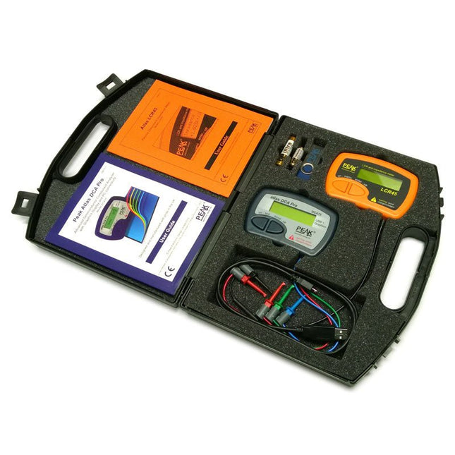
Peak Atlas Pro Pack (LCR45 & DCA75)
This pack contains the LCR45 Passive Component Impedance Meter, great for advanced hobbyists and professionals. It also contains the very popular DCA Pro (model DCA75), fantastic for component identification, pinout identification, detailed characteristic measurement and curve tracing on a PC. Complete with USB cable and software on a USB flash drive. DCA75 Building on the continued success of Peak's existing component identification and analysis instruments, the DCA Pro brings an array of exciting new features for the hobbyist and professional alike. The DCA Pro is an advanced new design that features a graphics display, USB communications, PC Software and an enhanced component identification library. Automatic component type identification Automatic pinout identification (connect any way round) The DCA Pro supports all the components that the popular Peak Atlas DCA55 supports, but adds plenty more. Components supported include: Transistors (including Darlingtons), Silicon and Germanium types. Measures gain, Vbe and leakage MOSFETs, enhancement mode and depletion mode types. Measure on-threshold (at 5 mA) and approx transconductance (for span of 3-5 mA) JFETs, including normally off SiC types. Measures pinch-off voltage (at 1 uA) and approx transconductance (for span of 3-5 mA) IGBTs (insulated gate bipolar transistors). Measures on-threshold (at 5 mA) Diodes and Diode networks LEDs and bicolour LEDs (2 lead and 3 lead types) Zener Diodes with measurement of zener voltage up to 9 V at 5 mA Voltage regulators (measures regulation voltage, drop-out voltage, quiescent current) Triacs and Thyristors that require less than 10 mA of gate current and holding current Stand-alone or with a PC The instrument can be used stand-alone or connected to a PC. Either way, the DCA Pro will automatically identify the component type, identify the pinout and also measure a range of component parameters such as transistor gain, leakage, MOSFET and IGBT threshold voltages, pn characteristics and much more. Curve Tracing When connected to a PC using the supplied USB cable, a range of low current curve-tracing functions can be performed. Various graph types are available, with more to follow: Bipolar transistor output characteristics, IC vs VCE Bipolar transistor gain characteristics, HFE vs VCE Bipolar transistor gain characteristics, HFE vs IC MOSFET and IGBT output function, ID vs VDS MOSFET and IGBT transfer function, ID vs VGS JFET output function, ID vs VDS JFET transfer function, ID vs VGS Voltage regulator, VOUT vs VIN Voltage regulator, IQ vs VIN. PN junction I/V curves, forward and reverse options (for Zener diodes) Curve tracing is performed using test parameters in the range of +/-12 V or +/-12 mA. All curve-tracing data can be instantly pasted into Excel for further graphing and analysis. PC Software is included with the DCA Pro on a Peak USB memory stick. Software designed for Windows 7 and higher (all 32 or 64 bit). LCR45 A great handheld LCR analyser that can measure the value of your passive component (inductor, capacitor or resistor) and also measure the detailed impedance in a number of modes. The LCR45 offers enhanced measurement resolution (better than 0.1 uH!) whilst also giving you continuous fluid measurements. Additionally, the test frequencies of DC, 1 kHz, 15 kHz and 200 kHz can be set to automatic or manual modes. Supplied with removable gold plated hook probes, battery and user guide. Compatible with standard 2 mm test connectors. Not designed for in-circuit use. Automatic or manual component type selection: Inductor, Capacitor or Resistor Automatic or manual test frequency selection: DC, 1 kHz, 15 kHz and 200 kHz Inductance from 0.1 uH to 10 H Capacitance from 0.1 pF to 10,000 uF Resistance from 0.1 Ohm to 2 MOhm Inductance measurement also shows DC winding resistance Display of "Component type and values", "Complex Impedance", "Magnitude/Phase" and "Admittance" Test frequency displayed for all measurements Typical accuracy of 1.5% for inductors and capacitors (see spec table for details) Typical accuracy of 1% for resistors Test lead complete with gold plated 2 mm plugs and sockets Supplied with removable gold plated hook probes Inbegrepen LCR45 DCA75 Extra GP23 Battery Extra AAA cell Dual Carry Case
€ 325,49
-
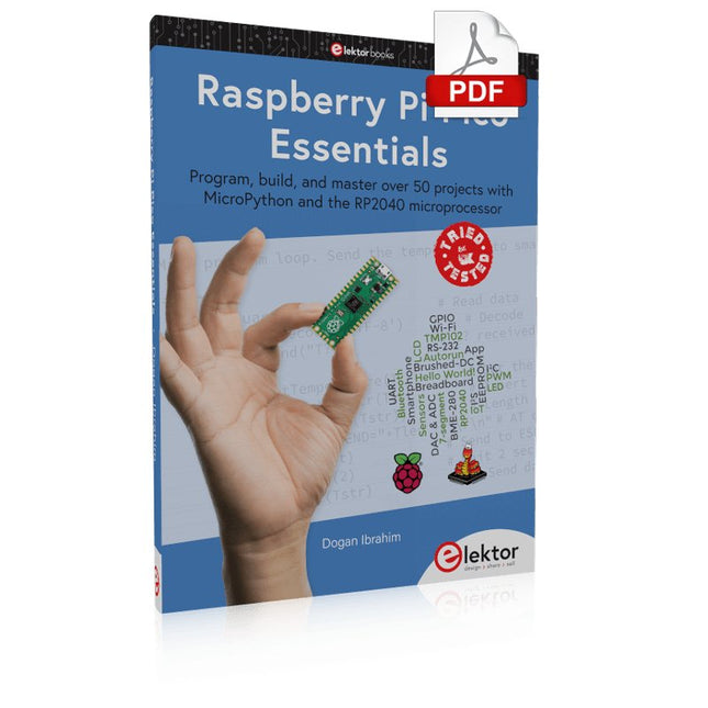
Elektor Digital Raspberry Pi Pico Essentials (E-book)
Program, build, and master over 50 projects with MicroPython and the RP2040 microprocessor The Raspberry Pi Pico is a high-performance microcontroller module designed especially for physical computing. Microcontrollers differ from single-board computers, like the Raspberry Pi 4, in not having an operating system. The Raspberry Pi Pico can be programmed to run a single task very efficiently within real-time control and monitoring applications requiring speed. The ‘Pico’ as we call it, is based on the fast, efficient, and low-cost dual-core ARM Cortex-M0+ RP2040 microcontroller chip running at up to 133 MHz and sporting 264 KB of SRAM, and 2 MB of Flash memory. Besides its large memory, the Pico has even more attractive features including a vast number of GPIO pins, and popular interface modules like ADC, SPI, I²C, UART, and PWM. To cap it all, the chip offers fast and accurate timing modules, a hardware debug interface, and an internal temperature sensor. The Raspberry Pi Pico is easily programmed using popular high-level languages such as MicroPython and or C/C++. This book is an introduction to using the Raspberry Pi Pico microcontroller in conjunction with the MicroPython programming language. The Thonny development environment (IDE) is used in all the projects described. There are over 50 working and tested projects in the book, covering the following topics: Installing the MicroPython on Raspberry Pi Pico using a Raspberry Pi or a PC Timer interrupts and external interrupts Analogue-to-digital converter (ADC) projects Using the internal temperature sensor and external temperature sensor chips Datalogging projects PWM, UART, I²C, and SPI projects Using Wi-Fi and apps to communicate with smartphones Using Bluetooth and apps to communicate with smartphones Digital-to-analogue converter (DAC) projects All projects given in the book have been fully tested and are working. Only basic programming and electronics experience is required to follow the projects. Brief descriptions, block diagrams, detailed circuit diagrams, and full MicroPython program listings are given for all projects described. Readers can find the program listings on the Elektor web page created to support the book.
€ 32,95
Leden: € 29,66
-

Elektor Digital Elektor September/Oktober 2023 (PDF)
Elektor GREEN en GOLD leden kunnen deze uitgave hier downloaden.Nog geen lid? Klik hier om een lidmaatschap af te sluiten. Raspberry Pi Pico als spectrumanalyzerFFT’s met goedkope hardware ±40 V lineaire spanningsregelaaralternatieve voeding voor de Fortissimo-100 eindversterker... en andere! Flexibele draadloze communicatie met een MCUEEPROM opent netwerkmogelijkheden voor draadloze MCU’s € 5000 voor het oprapen!doe mee aan de STM32 Wireless Innovation Design Contest 2023: een AI-odysseeaan de slag met Code Interpreter van ChatGPT LoRa – een Zwitsers zakmesdeel 1: het LoRa-protocol en zijn voordelen Instelbare current sink met geïntegreerde klokgeneratortest voedingen, spanningsconverters en accu’s Twee nieuwe Arduino UNO R4-boards: Minima en WiFi Logaritmische potentiometersze zijn exponentieel! Motordriver breakout-boardeen BoB voor een 5 A DC-motordriver van 3×3 mm Uit het leven gegrepenelektronica periculosa Biedt cellulair het laagste stroomverbruik voor IoT?energie-eisen van LTE-M en NB-IoT in LPWAN-implementaties Draadloze communicatie in IoT-systemen met Arduino MKR-moduleshet juiste board voor WiFi, LoRa en andere standaarden AC-verliezen in magnetische componentenvoorkom hete spoelen! Meten voor optimale cloud-connectiviteit Matter implementatie: Wat is er nodig om Matter-devices in te zetten? YARD Stick Onesub-1 GHz draadloos testtool Houdrelaisvreemde onderdelen PIC voor tien – precies op tijdontwerp van een SDR-tijdseinontvanger Due Diligence DirectiveBusiness as Usual Will Not Do Alle begin......versterkt spanningen Infrageluid-recorder met de Arduino Pro Minieen voorbeeldproject uit de Elektor-uitgave “Arduino & Co” Cloud-gebaseerde energiemetermet een ESP32-module en een PZEM-004T spanning/stroom-sensor Een gids voor puristisch programmeren (deel 2)nauwkeurige timing, de UART en debugging
€ 9,95
-

Elektor Digital 50 PIC Microcontroller Projects (E-book)
This book contains 50 fun and exciting projects for PIC microcontrollers such as a laser alarm, USB teasing mouse, eggtimer, youth repellent, soundswitch, capacitive liquid level gauge, 'finger in the water' sensor, guarding a room using a camera, mains light dimmer (110-240 volts), talking microcontroller and much more. Several different techniques are discussed such as relay, alternating current control including mains, I²C, SPI, RS232, USB, pulse width modulation, rotary encoder, interrupts, infrared, analog-digital conversion (and the other way around), 7-segment display and even CAN bus. You can use this book to build the projects for your own use. The clear explanations, schematics and even pictures of each project make this a fun activity. For each project the theory is discussed and why the project has been executed in that particular way. That means you can also use this book as a studybook, or as basis for larger and more complicated projects. All projects use a breadboard so modification and expansion is easy. Three PIC microcontrollers are used, the 16f877A, 18f4455 and 18f4685. It is also discussed how you can migrate your project from one microcontroller to another – 15 types are supported - including two example projects. All software that is used in this book can be downloaded for free. That also applies to the open source programming language JAL. This powerful and yet easy to learn language is used by hobbyists as well as professionals. This book can also be used as a reference guide. It explains all JAL commands, as well as the expansion libraries. Using the index you can easily find example projects that illustrate the use of these commands. Even when you have built all projects in this book you will still want to keep it within arm's reach.
€ 34,95
Leden: € 31,46
-

Elektor Labs Elektor Low-noise Labvoeding
De low-noise labvoeding van Elektor is een volledig analoge, instelbare, symmetrische unit met gemiddeld vermogen, zonder schakelende of digitale componenten. De uitgangsspanning is instelbaar tussen 0 V en ±22 V, en de uitgangsstroom kan worden ingesteld van 0 A tot 1 A. Doordat elke vorm van schakeltechniek wordt vermeden, levert het ontwerp extreem weinig ruis. Voor de weergave van beide uitgangsspanningen en -stromen worden vier kleine analoge paneelmeters met draaispoel gebruikt. De meeste moderne laboratoriumvoedingen en AC-adapters maken gebruik van schakelende technieken. Zelfs de beste uitvoeringen vertonen onvermijdelijk hoogfrequente rimpel en andere schakelartefacten op hun uitgang, die het testen van gevoelige analoge schakelingen kunnen verstoren en metingen van kleine signalen kunnen beïnvloeden. Om dit te voorkomen, is het concept hier een volledig analoge voeding. Hoewel deze minder efficiënt is dan vergelijkbare schakelende voedingen, is de lagere efficiëntie bij gebruik op de testbank nauwelijks van belang en zorgt deze voor schonere en betrouwbaardere meetresultaten. Omdat veel analoge schakelingen een symmetrische voeding vereisen, levert dit ontwerp positieve en negatieve uitgangsspanningen van gelijke grootte. Een kleine hoeveelheid afregeling is beschikbaar om eventuele onbalans te compenseren. Uiteraard is ook een instelbare stroombegrenzing aanwezig. De kit bevat de onderdelen die nodig zijn om de voeding te bouwen, met uitzondering van de transformatoren. Specificaties Uitgangsspanning 0…+22 V, 0, −22 V Uitgangsstroom 0…+1 A, 0…−1 A Ruis −85 dBV (bij 0,95 A/20 V, B = 22 kHz) −84 dBV (bij 0,95 A/20 V, B > 500 kHz) Rimpelspanning 50 µVRMS (bij 950 mA/20 V, B = 22 kHz, voornamelijk 100-Hz-component) Inbegrepen 3x printplaten: regelaar (PCB-1), netfilter (PCB-2) en transformator (PCB-3) Alle componenten, behalve de AC-transformatoren 4x draaispoelmeters Extra onderdelen voor de bedrading (draden, banaanstekkerbussen, IEC-voedingsmodule, enz.) Niet inbegrepen De drie AC-transformatoren Een behuizing Onderdelenlijst Voor de regelaar-printplaat (240386-1) Weerstanden (250 mW, 1%) R1 = 12 Ω R2, R8, R37, R62 = 1 MΩ R3, R7, R10, R13, R17, R20, R22, R30, R35, R42, R45, R47, R55, R60 = 100 Ω, 600 mW R4, R5 = 4.7 kΩ R6 = 100 kΩ R9, R12, R14, R36, R38, R39, R61, R63, R66, R72, R78, R79 = 10.0 kΩ, 600 mW R11 = 9.76 kΩ, 600 mW R15, R40 = 44.2 kΩ, 600 mW R16, R41, R77 = 1 kΩ R18, R43 = 1.5 kΩ, 1 W, 5% R19, R44 = 470 Ω, 1 W, 5% R21, R46 = 330 Ω, 600 mW R23, R24, R48, R49 = 1.0 Ω, 1 W R25, R50 = 1 kΩ, 1 W, 5% R26, R28, R51, R53 = 1.000 kΩ 0.1%, 15 ppm/C R27, R29, R52, R54 = 10.00 kΩ 0.1%, 15 ppm/C R31, R56 = 1.2 kΩ, 1 W, 5% R32, R57 = 47 kΩ R33, R58 = 270 Ω R34, R59 = 27 kΩ R64, R69 = 12.0 kΩ R65 = 3.0 kΩ, 600 mW R67, R80 = 470 Ω, 600 mW R68, R70 = 6.8 kΩ, 600 mW R71 = 30.0 kΩ,, 600 mW R73, R74, R75, R76 = 10 MΩ P1, P2, P3 = 10 kΩ, 200 mW, 20%, potentiometer, 1 turns, single, lin., panel mount P4, P5 = 500 Ω, 500 mW, 10%, trimmer, 25 turns, 3296Y-1-501LF Bourns P6, P7 = 10 kΩ, 500 mW, 10%, trimmer, 25 turns, 3296Y-1-501LF Bourns Condensatoren C1 = 100 nF, 50 V, 10%, ceramic X7R, LS 5 mm C2, C3, C6, C7, C30 = 10 µF, 63V, 20%, LS 2.5 mm, 3000hours@105°C C4, C5, C8, C9, C13, C14, C18, C19, C23, C24, C28, C29, C31, C32, C38, C39 = 100 nF, 250 V, 10%, PET, LS 7.5 mm C10, C20 = 47 nF, 100 V, 5%, PET, LS 5 mm C11, C21 = 10 nF, 100 V, 5%, PET, LS 5 mm C12, C22 = 220 µF, 35 V, 20%, 0.024 Ω, LS2.5/3.5 mm, Ir 3.4 A, 2000hours@125°C, polymer C15, C25 = 120 µF, 50 V, 20%, ESR 0.02 Ω, Diam. 10 mm max., LS 5 mm C16, C26 = 15 nF, 100 V, 5%, PET, LS 5 mm C17, C27 = 47 nF, 100 V, 5%, PET, LS 5 mm C33, C34 = 22 µF, 50 V, 20%, LS 2 mm, 10000 hours @ 105°C C35, C36, C44, C45 = 1 µF, 100 V, 10%, LS 5 mm, ceramic X7R C37 = 100 uF, 50 V, 20%. LS 3.5 mm C40, C41, C42, C43, C46, C47, C48, C49 = 1000 µF, 50 V, 20%, LS 5/7.5 mm, Ir 3.32 A, 10000hours@105°C, D 16 mm C50, C51, C52, C53 = 47 nF, 100 V, 10%, ceramic X7R, LS 5 mm Spoelen L1, L2 = 4.7 µH, 3.2 A, 0.033 Ω, LS 5 mm, RLB0914-4R7ML Bourns L3 = Commom mode choke, 14.5 mH, 3 A, SSRH24NH-30145 Kemet Halfgeleiders D1, D2, D3, D4, D5, D9, D10, D11, D15 = BAT85, DO-34 D6, D7, D12, D13 = SR560, DO-201AD D8, D14, D16 = 1N4148, DO-35 D17 = Zenerdiode, 5.6 V, 0.5 W, DO-41 D18, D19 = 1N4004, DO-41 D20, D21 D22, D23 = V30100CI-M3/P, dual common cathode, TO-220 D24 = Zener diode, 30 V, 1 W, DO-41 LED1, LED2 = LED, red, T-1 (3 mm) LED3, LED4 = LED, green, T-1 (3 mm) TVS1, TVS2 = BZW50-33B, R6 T1, T2, T4 = BC337.25, TO-92 T3 = NJW0302G, TO-3P T5, T6, T8 = BC327.25, TO-92 T7 = NJW0281G, TO-3P T9 = BD139, TO-126 (SOT-32) IC1 = LM334Z, TO-92 IC2 = LM4040AIZ-5.0/NOPB, TO-92 (TO-226AA-3) IC3, IC4 = OPA2992IDR, SOIC-8 IC5, IC6 = OPA4992IDR, SOIC-14 IC7 = OPA992IDBVR, SOT-23-5 IC8 = LM339N, DIP-14 IC9 = LM317, TO-220 IC10 = LM337, TO-220 Overige F1, F2 = 5×20 mm fuse, 1.6 A, fast acting HS1, HS2 = Heatsink MC33271 (for T3/T7), 2.7°C/W, PCB mount, height 63.5 mm K1, K4 = 3-way screw terminal block, LS 3.5 mm, max. 1.5 mm² K2, K3 = 3-way screw terminal block, LS 3.5 mm, max. 1 mm² M1, M3 = Moving coil meter, Range 30 V, type 91C4, 45×45 mm M2, M4 = Moving coil meter, Range 1 A, type 91C4, 45×45 mm² RE1 = Relay DPDT,5V, UA2-5NU Diversen 3× 3-way screw terminal block, LS 3.5 mm, max. 1 mm² (for P1, P2, P3) 4× Pin header, 1×2, vertical, pitch 2.54 mm (for LED1, LED2, LED3, LED4) 4× Pin socket, 1×2, vertical. pitch 2.54 mm (for LED1, LED2, LED3, LED4) 2× Heatsink FK222SA220, 20°C/W, PCB mount (for IC9 & IC10) 2× Mica thermal pad for TO-220, 12×18×0.05 mm (for IC9 & IC10) 2× Insulating bushing IB 6, TO-220 (for IC9 & IC10) 2× Ceramic thermal pad, 23×20×2 mm (for T3 & T7) 2× PCB Fuse Holder, for 5×20 mm fuse, 10 A (for F1, F2) 2× Cover for PCB Fuse Holder, transparent (for F1, F2) 2× 2-way screw terminal block, LS 3.5 mm, max. 1 mm² (for M1 & M3) 2× 2-way screw terminal block, LS 3.5 mm, max. 1.5 mm² (for M2 & M4) 8× M3 solder lug, thickness 0.35 mm (for M1…M4) M4 solder lug, thickness 0.35 mm (to connect 4 mm banana connectors) Screened cable, 1 pair, 2×24 AWG/0.22 mm², 1 m (for P1, P2 & P3) IC socket, DIP, 14 contacts (for IC8) M3 washer, plain, steel M3 screw, 16 mm, steel, pan head M3 nut M3 spring washer 50 mm M3 standoff, steel, male-female 12 mm M3 standoff, steel, male-female 10 mm M3 standoff, steel, male-female M3 screw, 8 mm, steel, pan head Voor de netfilter-printplaat (240386-2) Weerstand R1 = 220 kΩ, 1 W, 500 V, 5% Condensatoren C1, C2 = 470 nF, 305 VAC, Class X2, 11 × 27 mm max., LS 15/22.5 mm C3, C4, C5, C6 = 2.2 nF, 300 VAC, Class Y2, 13 × 4 mm, LS 10 mm, PP Spoelen L1, L2 = Common-mode choke, 6.8 mH, 1.7 A, TDK B82732R2172B030 Halfgeleider MOV1 = TVS varistor, 300 VAC, S14K300 (230 VAC, B72214S0301K101) and SK14K150 (150 VAC, B72214S0151K101) Overige K1, K2 = 3-way screw terminal block, LS 7.62 mm F1 = Time-delay fuse, 0.5 A (230 VAC) or 1 A (115 VAC) Diversen 1× Fuse holder, 5×20 mm, 10 A, 500 VAC 1× Transparent fuse cover 4× 10 mm M3 standoff, steel, male–female 4× M3 screw, 8 mm, steel, pan head 4× M3 nut Voor de transformator-printplaat (240386-3) Weerstanden R1, R2 = 2.7 kΩ, 600 mW, 1% R3 = 10.0 kΩ, 600 mW, 1% Condensator C1 = 220 µF, 50 V, 20%, Ø10 mm, LS 5 mm, 4000 h @ 105°C Transformatoren (niet inbegrepen in deze kit!) TR1, TR2, TR3 = 2×7 V, 25 VA, PCB-mounted toroid, 70060K Talema Halfgeleiders D1–D4 = 1N4148, DO-35 D5, D6 = 1N4004, DO-41 D7 = Zener 5.6 V, 1.3 W, DO-41 LED1 = LED, red, T-1 (3 mm) IC1, IC2 = MOC8021M, CTR ≥ 1000%, DIP-6 Overige F1, F2, F3 = 160 mA time-delay fuse (230 VAC) or 315 mA time-delay fuse (115 VAC) K1 = 2-way screw terminal block, LS 7.62 mm K2 = 3-way screw terminal block, LS 3.5 mm, max 1.5 mm² K3, K4 = 3-way screw terminal block, LS 3.5 mm, max 1 mm² RE1, RE2 = Relay DPDT, 5 A/250 VAC / 24 VDC Diversen 1× Pin header 1×2, pitch 2.54 mm + matching socket for LED1 3× Fuse holder 5 × 20 mm, 10 A, 500 VAC + transparent cover 3× M4 screw, 8 mm, pan head + washer for TR1-TR3 8× M3 screw, 8 mm, pan head + nut + washer 8× 10 mm M3 standoff, steel, male–female 2× IC socket, DIP-6 for IC1 & IC2 Extra onderdelen 1 m red insulated wire, stranded, 1.5 mm² 0.5 m blue insulated wire, stranded, 1.5 mm² 0.5 m black insulated wire, stranded, 1.5 mm², 0.5 m 2 m red insulated wire, stranded, D 0.56 mm (0.25 mm²) 2 m black insulated wire, stranded, D 0.56 mm (0.25 mm²) 0.5 m Multicore Cable, Flexible, 3 Core, 0.75 mm² (24 x 0.2 mm) Red banana socket Black banana socket Blue banana socket Green banana socket IEC Power Entry Module with switch, IEC C14 3 crimp terminals, FASTON, 4.75 x 0.81 mm 3 knobs Links Elektor Labs JumpStarter Page Artikel (deel 1) Artikel (deel 2)
€ 299,00€ 249,00Beste prijs
-

Elektor Digital Elektor Septembre/Octobre 2023 (PDF)
Le chargeur intégré est disponible pour nos clients OR et VERT sur le site d'Elektor Magazine ! Pas encore membre ? Cliquez ici . Raspberry Pi Pico comme analyseur de spectre des FFT avec du matériel bon marché régulateur de tension linéaire ±40 V une alimentation de qualité pour l'amplification du Fortissimo-100... et d'autres ! la communication sans fil des microcontrôleurs devient flexible l'EEPROM du point de vue de la mise en réseau pour les microcontrôleurs sans fil 5000 ? à gagner! participez au concours de conception d'innovation sans fil STM32 2023 : l'odyssée de l'IA en savoir plus sur le code ChatGPT LoRa, un couteau suisse (1) le protocole LoRa et ses avantages du courant réglable avec générateur de montre intégré testez vos alimentations, convertisseurs de tension et batteries les nouvelles cartes Arduino UNO R4 Minima et WiFi des potentiomètres logarithmiques qui sont exponentielles ! Carte d'interface pour pilote de moteur Un BoB pour un pilote continu de 5 A avec une taille de 3×3 mm sur le vif danger de l'électronique une architecture cellulaire de plus d'une consommation pour l'Internet des objets (IdO) ? Caractéristiques des technologies LTE-M et NB-IoT pour le développement de la basse consommation (LPWAN) communication sans utilisation de systèmes et d'aides IoT dans les modules Arduino MKR normes de communication pour les modules Arduino pour l'IoT pertes en courant alternatif dan les composants magnétiques évitez la surchauffe des inductances ! optimiser son déploiement cloud grâce aux équipements de mesure mise en œuvre de Matter : à quoi sert le déploiement des équipements de Matter ? le YARD Stick One en utilisant la méthode de test pour les fréquences de 1 GHz relais à verrouillage drôle de composant, la série PIC O?Horloge ? prendre le pouls du temps conception d'un récepteur de signaux horaires SDR Directive sur le devoir de diligence Le statu quo ne suffira pas démarrer en électronique ?amplificateur de tension activateur d'infrasons avec l'Arduino Pro Mini un projet extrait du livre 'Arduino & Co.' d'Elektor compteur d'énergie base sur le cloud avec un module ESP32 et un capteur tension/courant PZEM-004T guide de programmation Bare-Metal (2) timer précis, UART et débogage Hexadoku
€ 10,95
-
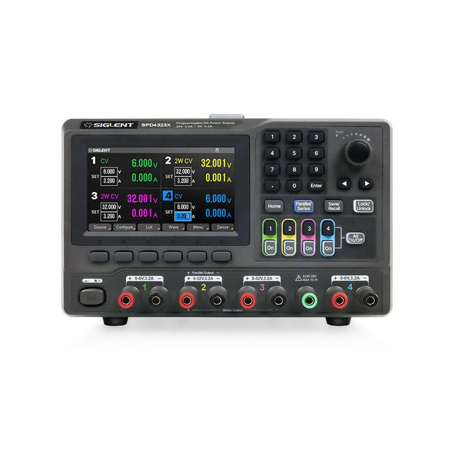
Siglent Siglent SPD4323X 4-kanaals Voeding (240 W)
The Siglent SPD4323X is a 4-channel DC Linear Programmable Power Supply equipped with a 4.3-inch TFT-LCD display, friendly human-machine interface, and excellent performance indicators. Real-time waveform display provides engineers with an informative user interface. SPD4323X offers a total output power of 240 W with a resolution of 1 mV/1 mA. The maximum voltage and current for each channel are as follows: CH1: 6 V/3.2 A CH2: 32 V/3.2 A CH3: 32 V/3.2 A CH4: 6 V/3.2 A Kenmerken Rated output power: 240 W Rated voltage: 32 V, 12 V, 30 V Up to four high-precision power supplies with independent controllable outputs, supporting CH2 and CH3 series and parallel connections Clear graphical interface with waveform and timer display modes 5-digit voltage and current display with minimum resolution of 1 mV, 1 mA Fast output response time: <50us The high current channel support remote voltage compensation sense function. The maximum compensation voltage is 0.6 V Overvoltage protection and overcurrent protection or safe and accurate operation Equipped with a 4.3-inch TFT-LCD display (480 x 272 resolution) USB and LAN standard communication USB-GPIB module is optional Excellent channel density with up to 4 channels in a 3U half rack package Internal data storage for setups and parameters Embedded Web Server with instrument communication that doesn’t require software installation Fully SCPI programming command set support as well as a LabView driver for remote control and system automation Specificaties SPD4323X SPD4121X SPD4306X Channel Output CH1: Voltage 0 to 6 V Current 0 to 3.2 ACH2: Voltage 0 to 32 V Current 0 to 3.2 ACH3: Voltage 0 to 32 V Current 0 to 3.2 ACH4: Voltage 0 to 6 V Current 0 to 3.2 A CH1: Voltage 0 to 15 V Current 0 to 1.5 ACH2: Voltage 0 to 12 V Current 0 to 10 ACH3: Voltage 0 to 12 V Current 0 to 10 ACH4: Voltage 0 to 15 V Current 0 to 1.5 A CH1: Voltage 0 to 15 V Current 0 to 1.5 ACH2: Voltage 0 to 30 V Current 0 to 6 ACH3: Voltage 0 to 30 V Current 0 to 6 ACH4: Voltage 0 to 15 V Current 0 to 1 A Resolution 1 mV, 1 mA 1 mV, 1 mA 1 mV, 1 mA Setting Accuracy Voltage: ±(0.03% of reading+10) mV, Current: ±(0.3% of reading+10) mA Voltage: ±(0.03% of reading+10) mV, Current: ±(0.3% of reading+10) mA Voltage: ±(0.03% of reading+10) mV, Current: ±(0.3% of reading+10) mA Readback Accuracy Voltage: ±(0.03% of reading+10) mV, Current: ±(0.3% of reading+10) mA Voltage: ±(0.03% of reading+10) mV, Current: ±(0.3% of reading+10) mA Voltage: ±(0.03% of reading+10) mV, Current: ±(0.3% of reading+10) mA Display 4.3" TFT-LCD 5-digit voltage and current display 4.3" TFT-LCD 5-digit voltage and current display 4.3" TFT-LCD 5-digit voltage and current display Output power 240 W 285 W 400 W Inbegrepen 1x Siglent SPD4323X Power Supply 1x Power cord (EU) 1x Output test cord (3 A) 1x USB cable 1x Quick start guide Downloads Datasheet Manual Quick start
€ 762,30
-

Elektor Digital Elektor 09-10/2026 (PDF) DE
Diese Ausgabe steht allen GOLD- und GREEN-Mitgliedern auf der ElektorMagazine-Website zum Download bereit! Sie sind noch kein Mitglied? Hier klicken! Der ESP-BLASTEine Mini-Raketendrohne mit ESP32, die über 100 km/h erreicht Wireless Workshop (1)Freigeschaltetes Funkmodul: 433-MHz-CC1101-Sub-GHz-Transceiver AM-Sendermit Rechteck-/Sinuswellengenerator auf Raspberry Pi Pico STM32Cube Innovations ChallengeTreten Sie mit Ihrem besten STM32C5-Design an CoffeeCallerWie ein langer Flur zu einer maßgefertigten Mesh-Netzwerk-Platine führte AudiotronicsKlirrfaktor Elektor ist 65Projekte aus früheren September/Oktober-Ausgaben Geräteortung durch Bluetooth Channel SoundingZentimetergenaue Entfernungsmessung im IoT der nächsten Generation 2026: Eine KI-OdysseeQuantencomputing ist nicht die nächste GPU Cloud-Schutz durch Edge-Sicherheit Erste Erfahrungen mit dem HackRF ProPraktische Tests mit der neuen SDR-Hardware Herausforderung ElektromobilitätEffiziente Lötlösungen für moderne Fahrzeugtechnik Modem-Update von GPRS/2G auf LTE/4Gam Beispiel einer Funk-Alarmzentrale Loop-Antenne mit RF BricksTeil 1: Kurzwellen-Antenne mit einstellbarer Richtwirkung im Selbstbau Internetradio-zu-AM-KonverterVerwendung eines ESP32-S3 als Sender Projekt 2.0 mioty – ein ÜberblickLPWAN à la Fraunhofer Werkbank-WeisheitPraktische Tipps von Experten Walter, das kompakte IoT-ModulTeil 2: Zugriff auf Wetter- und Datendienste
€ 11,90
-

Elektor Digital Inside an Open-Source Processor (E-book)
An Introduction to RISC-V RISC-V is an Instruction Set Architecture (ISA) that is both free and open. This means that the RISC-V ISA itself does not require a licensing fee, although individual implementations may do so. The RISC-V ISA is curated by a non-profit foundation with no commercial interest in products or services that use it, and it is possible for anyone to submit contributions to the RISC-V specifications. The RISC-V ISA is suitable for applications ranging from embedded microcontrollers to supercomputers. This book will first describe the 32-bit RISC-V ISA, including both the base instruction set as well as the majority of the currently-defined extensions. The book will then describe, in detail, an open-source implementation of the ISA that is intended for embedded control applications. This implementation includes the base instruction set as well as a number of standard extensions. After the description of the CPU design is complete the design is expanded to include memory and some simple I/O. The resulting microcontroller will then be implemented in an affordable FPGA development board (available from Elektor) along with a simple software application so that the reader can investigate the finished design.
€ 32,95
Leden: € 29,66
-

Elektor Digital Elektor 01-02/2023 (PDF)
Diese Ausgabe steht allen GOLD- und GREEN-Mitgliedern auf der ElektorMagazine-Website zum Download bereit! Sie sind noch kein Mitglied? Hier klicken! Für Augen und Ohren Videoausgabe mit MikrocontrollernTeil 1: Composite Video electronica 2022Neues von der Weltleitmesse ESP32-KameraSo einfach, dass sie nicht einmal WLAN braucht ATX-Netzteil für Raspberry Pi 32-?-KopfhörerverstärkerEinfache, aber hochqualitative 3-Chip-Lösung SDR-FunkuhrenFünf Zeitzeichen, sechs Anzeigen Aller Anfang ...muss nicht schwer sein: Spezielle Dioden Aus dem Leben gegriffenÜber die Qualität der Dinge Reverse-Engineering eines LED-Displays mit Bluetooth Low EnergyWie man ein BLE-Gerät mit einem Python-Skript steuert MakePython ESP32 Development KitAlles in einer Box THD-Messung mit Oszilloskop und FFTDen Klirrfaktor einfach berechnen Allsehende MaschinenDie Technologie hinter modernen industriellen Bildverarbeitungssystemen Infografik Die Entwicklung der Sprach- und Audiosteuerung für elektronische Geräte WEEF 2022 im Rückblick Im Rückblick: FFWD electronica 2022Innovatoren beeindrucken weiterhin! The TubeEin Röhrenverstärker der anderen Art Biomaterialien in der Elektronik: Bereit oder nicht? Opera-Cake-Antennenumschalter für HackRF OneSchließen Sie bis zu acht Antennen an Ihr SDR an Technik mit Arduino und mehrEin Interview mit Autor Ashwin Pajankar LiDAR-PräzisionsmetermaßMisst bis zu zwölf Meter Audio mit dem ESP32Das Framework ESP-ADF in der Praxis Elektor-Leistungsverstärker-Bausatz Fortissimo-100 Licht für Klangeffekte nutzenLDR-basiertes spannungsgesteuertes 24 dB/Okt.-Synthesizer-Filter Hochleistungsverstärker GigantDer Lauteste von allen!! Betreten für Unbefugte verboten!Ein volumetrisches Display Made in Canada Projekt 2.0Korrekturen, Updates und Leserbriefe Hexadoku
€ 11,90
-

Elektor Digital Elektor Januari/Februari 2023 PDF (NL)
Elektor GREEN en GOLD leden kunnen deze uitgave hier downloaden.Nog geen lid? Klik hier om een lidmaatschap af te sluiten. Voor ogen en oren Video-output met microcontrollers (1)Composiet Video electronica 2022nieuws van 's werelds grootste elektronicabeurs ESP32-camerazo simpel – heeft niet eens WiFi ATX-voeding voor Raspberry Pi 32 Ω KoptelefoonversterkerEenvoudige maar hoogwaardige 3-chip oplossing SDR-radioklokkenvijf tijdsignalen, zes displays Alle begin......zet een streep onder de diode Uit het leven gegrepenover de kwaliteit der dingen Reverse-engineering van een Bluetooth Low Energy LED-badgeeen BLE-apparaat besturen met een Python-script MakePython ESP32 Development KitAlles in een doosje THD-meting met een oscilloscoop en FFTgemakkelijke berekening van de vervormingsfactor Allesziende machinesde technologie achter moderne industrële visionsystemen Infographics De evolutie van spraak- en audiogestuurde elektronische apparaten WEEF 2022 terugblik FFWD elektronica 2022 terugblikde vernieuwers hebben niet nagelaten indruk te maken The Tubeeen ongebruikelijke buizenversterker Biomateriaal in elektronica: klaar of niet De Opera Cake antenne switch voor HackRF OneSluit tot acht antennes aan op uw SDR Engineering met de Arduino, en meerEen interview met auteur Ashwin Pajankar LiDAR-precisiemetermeet tot 12 meter Audiosignalen en de ESP32De ESP-ADF-omgeving in de praktijk Elektor Fortissimo-100 einversterker-kit Lichtgestuurde geluidseffectenSpanningsgestuurd 24 dB/oct synthesizerfilter (VCF) met LDR's De kilo-watter van Elektuurmeer volume gaat niet! Oost West Lab Besteen volumetrisch display in Canada Project 2.0Correcties, Updates en Brieven van lezers Hexadoku
€ 9,95
-

Elektor Mars/Avril 2025 (FR)
Le téléchargement intégral de ce numéro est disponible pour nos membres GOLD et GREEN sur le site Elektor Magazine ! Pas encore membre ? Cliquez ici. L'architecture de processeur open-source RISC-V16 cartes et MCU à connaître un lecteur audio avec égaliseur basé sur un FPGAMixage audio numérique avec un Arduino MKR Vidor 4000 tête laser pour l’horloge de sable basé sur Raspberry Pi PicoDessiner avec la lumière participez au concours STM32 Edge AI système de contrôle environnemental multi-capteurs pour les plantesMesure sans fil de l'approvisionnement en eau et de la luminosité porte automatique contrôlée par l'IA et MaixduinoReconnaissance faciale avec une caméra l’électronique embarquée en 2024L’IA va redéfinir l’industrie Calcul en mémoire basé sur la charge chez EnCharge AI des opérations d'IA avec 10 fois moins d'énergie et des coûts divisés par 20 Une carte pour le développement et l’entraînement des modèles ML d’analyse des vibrations Elektor Mini-WheelieKit robot gyropode (robot autostabilisé) MCUViewerMCUViewer outil de débogage open source multiplateforme isolateur USB 2.0Isolation éléctrique pour les périphériques USB anticipation et actionApplication pratique de la maintenance prédictive SPoE – compatibilité électromagnétiquePaire unique avec Power-over-Ethernet à travers les yeux d'EMC rétro-techCréer un monde nouveau avec la télévision couleur surveillance ECGavec des modules Hexabitz et STM32CubeMonitor la bataille pour l’IA en périphérie HaLow atteint une distance Wifi record de 16 km à 900 MHz première puce embarquée CHERI RISC-V et programme d'accès anticipé la détection des incendies de forêt de troisième génération utilise des liaisons satellites sur le vifDélices et supplices du choix démarrer en électronique......Filtrage et contrôle de la tonalité Kit d'horloge quasi-analogiqueNouvelle version d'un classique d'Elektor une approche modulaire de test des capteursCarte de test de capteurs basée sur l'ESP32-S3 2025 : une odyssée de l'IAL'essor des modèles de fondation et leur impact sur l'accessibilité de l'IA Synthétiseur MIDI autonome Raspberry Pi (1)Préparation d'une plateforme pour des expériences d’IA en périphérie projet 2.0Corrections, mises à jour et courrier des lecteurs Le RISC-V AI, un processeur à tout faire : CPU, GPU, DSP, FPGA paroles de PDG : fraîcheur, silence et finesse programmation Dual-Core avec le Raspberry Pi PicoLe monde de la programmation parallèle
€ 15,50


