
Zoekresultaten voor "sdr"
-

Elektor Digital Elektor July/August 2020 (PDF) EN
Home Information SystemUsing Windows on a Raspberry Pi Starting with Node-REDAn open-source visual block-based programming tool Elektor Summer GiveAway Simple Function Generator: With Reverse-Order Signal Creation GreatScott! Builds a LoRa Alarm System Review: Joy-iT RD6006 Benchtop Power Supply Kit Review: The GreatFET One Interface Board Small Circuits Revival – XXLEscaped from the Suggestions Box Poorest Man's External 2.4 GHz Wi-Fi Antenna Simple On-Off Temperature Controller with Raspberry Pi HAT How to Take (Successful) Photos of ElectronicsShowing your projects in their best light Review: The I2CDriver Tool Review: JOY-iT Joy-View Portable Touchscreen LED Booster for MicrocontrollersWith just one component Experimental Ultrasonic Clothes Washer Review: The Joy-iT JDS2915 Signal GeneratorA 2-Channel Signal Generator and Frequency Counter Traffic Lights Programmed in PIC Assembly Code E-E-E-ternal Blinker Experimental Hall Sensor Tracing Shorts with the Milli-Ohm or ESR Meter Review: Elektor SDR Hands-on Kit Elektor Labs Pipeline Elektor KickstarterWell, you get the idea. Do You Really Need All That Stuff???This is where I spend many hours working on electronics projects Homelab Tours: The Kinetic Clock MakerStargate jigsawed! Hello, World! We’re Elektor, and We’re Social M4 + 2x A7 + GPU: An Unbalanced Dream TeamLatest STM32MP1-SoCs can tackle demanding applications Test Rig for 16F18877 & Similar Big PICs Inter-Microcontroller Traffic with the SPI Bus and ATmega328p Six Shades of LF/AF OSC (and the Miller’s Tale) BBC micro:bit Absolute Minimalist Oscilloscope with LED Display ‘Knight Rider’ LED Chaser with the ESP32 LW/MW AM Signal Generator with ATtiny13 Absolute Minimalist Dip Meter Photovoltaic Regulator UpdateNew function for measuring battery temperature Wireless SignallingTransmitting switching signals over LPR Ultrasonic Reverse Parking Aid with Arduino Uno Distortion Pedal with Op Amp and Space Charge Tubes Electronics Workspace Essentials Hexadoku Artificial Intelligence for Beginners (2)Neural networks with Linux and Python
€ 7,50
-

Siglent Siglent SDS1204X-E 4-kanaals Oscilloscoop (200 MHz)
The Siglent SDS1204X-E is a powerful 200 MHz four-channel oscilloscope that is built on the same platform as the very popular SDS1202X-E but with several significant improvements, including two 1 GSa/s ADCs and two 14 Mpt memory modules. Waveform capture rates are up to 100,000 wfms/s in normal mode and 400,000 wfms/s in sequence mode. The SDS1000X-E scopes feature a large 7” 256-level color display with intensity grading and color temperature features. Specificaties Bandwidth 200 MHz Sampling Rate (Max.) 1 GSa/s Channels 2CH+EXT4CH Memory Depth (Max.) 7 Mpts/CH (not interleave mode); 14 Mpts/CH (interleave mode) Waveform Capture Rate (Max.) 100,000 wfms/s (normal mode), 400,000 wfms/s (sequence mode) Trigger Types Edge, Slope, Pulse width, Window, Runt, Interval, Dropout, Pattern, Video Serial Trigger (Standard) I2C, SPI, UART/RS232, CAN, LIN Decode Type (Standard) I2C, SPI, UART/RS232, CAN, LIN 16 Digital Channels (four channel series only, option) Maximum waveform capture rate up to 1 GSa/s, Record length up to 14 Mpts/CH USB AWG module (four channel series only, option) One channel, 25 MHz, sample rate of 125 MHz, wave length of 16 kpts Bode plot ( four channel series only) Minimum start frequency of 10 Hz, minimum scan bandwith of 500 Hz, maximum scan bandwidth of 120 MHz (dependent on Oscilloscope and AWG bandwidth), 500 maximum scan frequency points USB WIFI adapter (four channel series only, option) 802.11b/g/b, WPA-PSK, the adapter must be supplied by Siglent to ensure proper functioning Downloads Datasheet Manual Programming Guide
€ 781,44
-

Elektor Labs Elektor Super Servo Tester Kit
De Elektor Super Servo Tester kan servo's aansturen en servosignalen meten. Hij kan tot vier servokanalen tegelijkertijd testen. De Super Servo Tester wordt geleverd als bouwpakket. Alle onderdelen die nodig zijn om de Super Servo Tester in elkaar te zetten zijn inbegrepen in de set. Het bouwen van de kit vereist enige basisvaardigheid met solderen. De microcontroller is al geprogrammeerd. De Super Servo Tester beschikt over twee bedrijfsmodi: Control/Manual en Measure/Inputs. In de modus Control/Manual genereert de Super Servo Tester besturingssignalen op zijn uitgangen voor maximaal vier servo's, of voor de flight controller of ESC. De signalen worden ingeregeld door de vier potentiometers. In de modus Measure/Inputs meet de Super Servo Tester de servosignalen die op de ingangen zijn aangesloten. Deze signalen kunnen afkomstig zijn van bijvoorbeeld een ESC, een flight controller, of de ontvanger, of een ander apparaat. De signalen worden ook naar de uitgangen geleid om de servo's of de flight controller of ESC aan te sturen. De resultaten worden op het display weergegeven. Specificaties Operating modi Control/Manual & Measure/Inputs Kanalen 3 Servosignaal ingangen 4 Servosignaal uitgangen 4 Alarm Zoemer & LED Weergave 0,96" OLED (128 x 32 pixels) Ingangsspanning op K5 7 - 12 VDC Ingangsspanning op K1 5 - 7,5 VDC Ingangsstroom 30 mA (9 VDC op K5, en niets aangesloten op K1 en K2) Afmetingen 113 x 66 x 25 mm Gewicht 60 g Inbegrepen Weerstanden (0,25 W) R1, R3 1 k?, 5% R2, R4, R5, R6, R7, R9, R10 10 k?, 5% R8 22 ?, 5% P1, P2, P3, P4 10 k?, lin/B, verticale potentiometer Condensatoren C1 100 ?F 16 V C2 10 ?F 25 V C3, C4, C7 100 nF C5, C6 22 pF Halfgeleiders D1 1N5817 D2 LM385Z-2.5 D3 BZX79-C5V1 IC1 7805 IC2 ATmega328P-PU, geprogrammeerd LED1 LED, 3 mm, rood T1 2N7000 Diversen BUZ1 Piëzo-zoemer met oscillator K1, K2 2-rijige, 12-voudige pinheader, 90° K5 Barrel jack K4 1-rijige, 4-polige pinvoet K3 2-rijige, 6-voudige boxed pinheader S1 Schuifschakelaar DPDT S2 Schuifschakelaar SPDT X1 Kristal, 16 MHz 28-voudige DIP-voet voor IC2 Elektor printplaat OLED-scherm, 0,96", 128 x 32 pixels, 4-pins I²C-interface Links Elektor Magazine Elektor Labs
€ 59,95€ 49,95Beste prijs
-
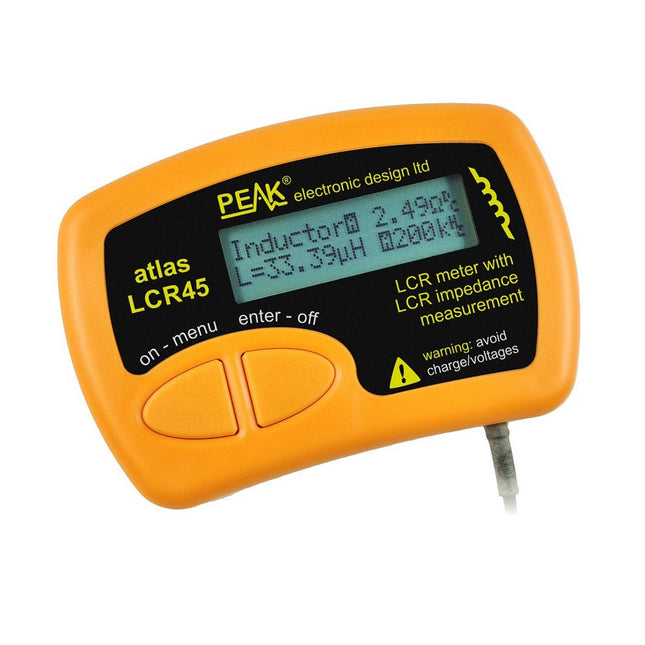
Peak Peak Atlas LCR45 LCR-meter
The LCR45 does everything that the popular LCR40 does, but it has some significant enhancements. The LCR45 features a new high capacity micro and high resolution ADCs. LCR45 incorporates advanced maths, based on Complex Impedance analysis. This allows for enhanced component value measurement as well as a comprehensive and detailed impedance display. Kenmerken Supplied with gold plated removable hook probes. Fluid measurements with hold function. Automatic or manual component type. Automatic or manual test frequency, DC, 1 kHz, 15 kHz or 200 kHz. Enhanced measurement resolution: 0.2 µH, 0.2 pF and 0.2 Ohms. Easy menu system for user settings. Enhanced compensation for component parasitics and losses (such as core losses etc). Automatic or manual power-off. Specificaties Analyser type LCR and component impedance Component types Auto/Manual for L,C & R Measurement types Inductance, Capacitance and Resistance Other measurements Complex impedance/admittance More measurements Magnitude and Phase of impedance Inductance range 0uH to 2H Capacitance range 0 pF to 10000 uF Resistance range 0R to 2MR Test frequency Auto and manual: DC, 1 kHz, 15 kHz, 200 kHz Display type Alphanumeric LCD (not backlit) Measurement scheme Continuous (with optional hold) Battery GP23 (12 V/55 mAH type), ~700 ops Inbegrepen LCR45 Passive Component Impedance Meter 2 mm plugs and sockets and removeable hook probes Comprehensive illustrated user guide 2 Batteries, one installed and one spare. GP23 Alkaline battery. (12 V/55 mAH) Downloads Datasheet (EN) User Guide (EN)
€ 131,89
-
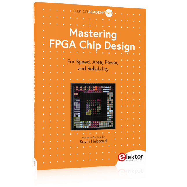
Elektor Publishing Mastering FPGA Chip Design
For Speed, Area, Power, and Reliability This book teaches the fundamentals of FPGA operation, covering basic CMOS transistor theory to designing digital FPGA chips using LUTs, flip-flops, and embedded memories. Ideal for electrical engineers aiming to design large digital chips using FPGA technology. Discover: The inner workings of FPGA architecture and functionality. Hardware Description Languages (HDL) like Verilog and VHDL. The EDA tool flow for converting HDL source into a functional FPGA chip design. Insider tips for reliable, low power, and high performance FPGA designs. Example designs include: Computer-to-FPGA UART serial communication. An open-source Sump3 logic analyzer implementation. A fully functional graphics controller. What you need: Digilent BASYS3 or similar FPGA eval board with an AMD/Xilinx FPGA. Vivado EDA tool suite (available for download from AMD website free of charge). Project source files available from author’s GitHub site.
€ 39,95
Leden: € 35,96
-
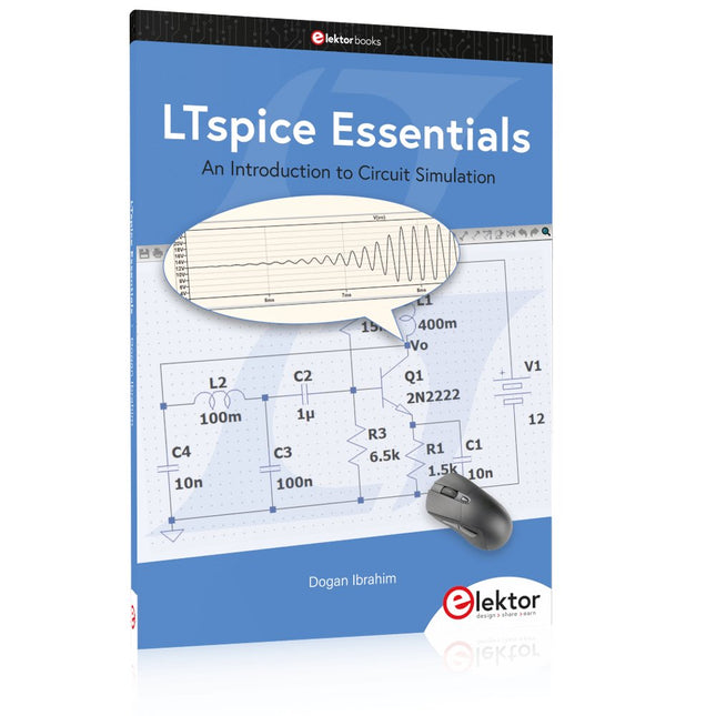
Elektor Publishing LTspice Essentials
An Introduction to Circuit Simulation LTspice, developed by Analog Devices, is a powerful, fast, and free SPICE simulator, schematic capture, and waveform viewer with a large database of components supported by SPICE models from all over the world. Drawing a schematic in LTspice is easy and fast. Thanks to its powerful graphing features, you can visualize the voltages and currents in a circuit, and also the power consumption of its components and much more. This book is about learning to design and simulate electronic circuits using LTspice. Among others, the following topics are treated: DC and AC circuits Signal diodes and Zener diodes Transistor circuits including oscillators Thyristor/SCR, diac, and triac circuits Operational amplifier circuits including oscillators The 555 timer IC Filters Voltage regulators Optocouplers Waveform generation Digital logic simulation including the 74HC family SPICE modeling LTspice is a powerful electronic circuit simulation tool with many features and possibilities. Covering them all in detail is not possible in a book of this size. Therefore, this book presents the most common topics like DC and AC circuit analysis, parameter sweeping, transfer functions, oscillators, graphing, etc. Although this book is an introduction to LTspice, it covers most topics of interest to people engaged in electronic circuit simulation. The book is aimed at electronic/electrical engineers, students, teachers, and hobbyists. Many tested simulation examples are given in the book. Readers do not need to have any computer programming skills, but it will help if they are familiar with basic electronic circuit design and operation principles. Readers who want to dive deeper can find many detailed tutorials, articles, videos, design files, and SPICE circuit models on the Internet. All the simulation examples used in the book are available as files at the webpage of this book. Readers can use these example circuits for learning or modify them for their own applications.
€ 39,95
Leden: € 35,96
-

Elecrow Elecrow AI Starter Kit voor Jetson Orin Nano
Alles-in-één AI-leer- en ontwikkelplatform voor Edge Intelligence Deze op NVIDIA Jetson gebaseerde AI-starterkit is een veelzijdig platform voor leren, ontwikkelen en praktisch experimenteren met Edge AI. De kit is ontworpen voor gebruik met de NVIDIA Jetson Orin Nano en combineert een 11,6-inch IPS-scherm, een 8-megapixel pan-tilt-camera en een AI-systeem voor spraakinteractie. Het pakket bevat 30 functionele modules en 38 zorgvuldig samengestelde Python-cursussen die variëren van beginners- tot gevorderd niveau. De cursusinhoud behandelt de basisbeginselen van Python, sensortechnologie, AI-vision en beeldherkenning. Dankzij stapsgewijze praktijkoefeningen – variërend van basisprogrammering tot praktische toepassingen van computer vision – vormt deze kit een ideaal platform voor studenten, makers, ontwikkelaars en iedereen die zich wil verdiepen in kunstmatige intelligentie en edge computing. Let op: De NVIDIA Jetson Orin Nano is niet inbegrepen. Kenmerken Ontworpen voor de NVIDIA Jetson Orin Nano AI-module voor spraakinteractie 8 MP-camera met pan-tilt-besturing Ondersteunt object- en gezichtstracking Geen solderen of complexe bedrading nodig Ingebouwd 11,6-inch IPS-scherm 30 functionele modules 38 stapsgewijze Python-lessen Uitbreidingsinterfaces voor I²C, UART en GPIO Inclusief draagtas Specificaties Hoofdprocessor Jetson Orin Nano Aantal sensoren 30 Ontwerp sensorbord Geïntegreerd sensorbord; solderen of complexe bedrading niet nodig Scherm 11,6-inch IPS-scherm Schermresolutie 1366 x 768 Camera IMX219 8MP Uitbreidingsinterfaces 2x I²C, 1x UART, 1x IO D13, 1x IO D12 Programmeeromgeving Gebaseerd op Python Aantal tutorials 38 creatieve tutorials Doelgroep Studenten, docenten, hardware-enthousiastelingen Toepassingen Ideaal voor het leren programmeren van AI en de basisbeginselen van de Jetson Orin Nano Afmetingen 300 x 200 x 100 mm Modulelijst Module Aantal Temperatuur- en vochtigheidssensor 1 st. Drukknop 4 st. Ultrasone afstandssensor 1 st. Lichtsensor 1 st. Lineaire potentiometer 1 st. Zoemer 1 st. LCD-scherm 1 st. Infraroodafstandsbediening 1 st. Relais 1 st. NFC-module 1 st. PIR-bewegingssensor 1 st. Joystick 1 st. 4-cijferig display 1 st. LED 1 st. Microfoon 1 st. Luidspreker 1 paar Trilmotor 1 st. Aanraaksensor 1 st. 8x8 RGB-matrix 1 st. Luchtdruksensor 1 st. Kantelschakelaar 1 st. Stappenmotor 1 st. Versnellingsmeter & gyroscoop 1 st. Gassensor (MQ2) 1 st. Hallsensor 1 st. Draai-encoder 1 st. U-vormige optische schakelaar 1 st. NTC-sensor 1 st. Servomotor 2 st. Monoculaire camera 1 st. Inbegrepen 1x Elecrow AI Starter Kit voor Jetson Orin Nano 1x Infraroodafstandsbediening 1x NFC-kaart 1x 128 GB SD-kaart 1x 40-pins GPIO-kabel 2x 22-pins FPC-kabel 2x 24-pins FPC-kabel 1x Jetson DP- & USB-adapterbord Niet inbegrepen NVIDIA Jetson Orin Nano Downloads Manual Wiki OpenClaw Install and Config Guide
€ 249,00
Leden: € 224,10
-

Elektor Digital The ESP32 Cheap Yellow Display Book (PDF)
Projects Using Arduino IDE and the LVGL Graphics Library The ESP32 is probably one of the most popular microcontrollers used by many people, including students, hobbyists, and professional engineers. Its low cost, coupled with rich features makes it a popular device to use in many projects. Recently, a board called the ESP32 Cheap Yellow Display (CYD for short) is available from its manufacturers. The board includes a standard ESP32 microcontroller together with a 320x240 pixel TFT display. Additionally, the board provides several connectors for interfaces such as GPIO, serial port (TX/RX), power and Ground. The inclusion of a TFT display is a real advantage as it enables users to design complex graphics-based projects without resorting to an external LCD or graphics displays. The book describes the basic hardware of the ESP32 CYD board and provides details of its on-board connectors. Many basic, simple, and intermediate-level projects are given in the book based on the ESP32 CYD, using the highly popular Arduino IDE 2.0 integrated development environment. The use of both the basic graphics functions and the use of the popular LVGL graphics library are discussed in the book and projects are given that use both types of approaches. All the projects given in the book have been tested and are working. The block diagram, circuit diagram, and the complete program listings and program descriptions of all the projects are given with explanations. Readers can use the LVGL graphics library to design highly popular eye-catching full-color graphics projects using widgets such as buttons, labels, calendars, keypads, keyboards, message boxes, spinboxes, sliders, charts, tables, menus, bars, switches, drop-down lists, animations, and many more widgets.
€ 29,95
Leden: € 26,96
-
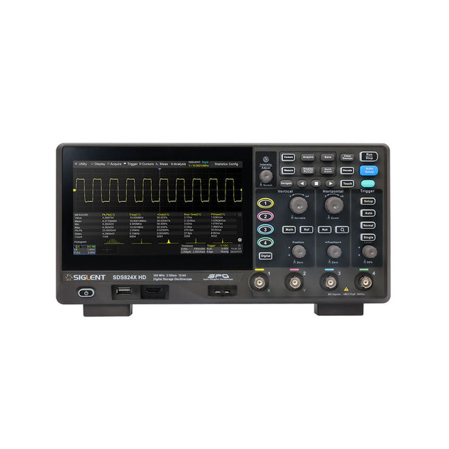
Siglent Siglent SDS814X HD 4-kanaals Oscilloscoop (100 MHz)
The Siglent SDS814X HD digital storage oscilloscope is based on 2 GSa/s, 12-bit Analog-Digital Converters and front ends with excellent noise floor performance. With a 100 MHz bandwidth, and a maximum record length of 50 Mpts, and the capability to analyze 4 analog channels alongside 16 digital channels, the SDS814X HD is perfectly suited for mixed signal analysis. Kenmerken 12-bit High Resolution 12-bit Analog-Digital Convertors with sample rate up to 2 GSa/s Front ends with 70 μVrms noise floor @ 100 MHz bandwidth 2/4 analog channels, up to 700 MHz bandwidth SPO technology Waveform capture rate up to 80,000 wfm/s (normal mode), and 500,000 wfm/s (sequence mode) Supports 256-level intensity grading and color temperature display modes. Up to 50 Mpts record length Digital trigger system Intelligent trigger: Edge, Slope, Pulse width, Window, Runt, Interval, Dropout, Pattern, Video (HDTV supported), Qualified, Nth edge, Delay, Setup/Hold time. Serial bus triggering and decoder, supports protocols I²C, SPI, UART, CAN, LIN. Segmented acquisition (Sequence) mode, dividing the maximum record length into multiple segments (up to 80,000), according to trigger conditions set by the user, with a very small dead time between segments to capture the qualifying event. History waveform record (History) function, the maximum recorded waveform length is 80,000 frames. Automatic measurements on 50+ parameters, supports statistics with histogram, track, trend, Gating measurement, and measurements on Math, History and Ref. 4 Math traces (2 Mpts FFT, addition, subtraction, multiplication, division, integration, differential, square root, etc.), supports formula editor. Abundant data analysis functions such as Search, Navigate, Counter, Bode plot and Power Analysis High Speed hardware-based Mask Test function, with Mask Editor tool for creating user-defined masks 16 digital channels (optional) 25 MHz waveform generator (optional) 7" TFT-LCD display with 1024 x 600 resolution; Capacitive touch screen supports multi-touch gestures. Interfaces include: USB Hosts, USB Device (USBTMC), LAN (VXI-11/Telnet/Socket), Pass/Fail, Trigger Out Built-in web server supports remote control over the LAN port using a web browser. Supports SCPI remote control commands. Supports external mouse and keyboard. Supports NTP. Specificaties Analog Channels 4 Bandwidth 100 MHz Vertical resolution 12-bit Sample rate (Max.) One channel mode: 2 GSa/sTwo channel mode: 1 GSa/sFour channel mode: 500 MSa/s Memory depth (Max.) One channel mode: 50 Mpts/chTwo channel mode: 25 Mpts/chFour channel mode: 10Mpts/ch Waveform capture rate (Max.) Normal mode: 80,000 wfm/sSequence mode: 500,000 wfm/s Trigger type Edge, Slope, Pulse width, Window, Runt, Interval, Dropout, Pattern, Video, Qualified, Nth edge, Delay, Setup/Hold time, Serial Serial trigger and decode (Standard) I²C, SPI, UART, CAN, LIN Measurement 50+ parameters, statistics, histogram, trend, and track supported Math 4 traces 2 Mpts FFT, Filter, +, -, x, ÷, ∫dt, d/dt, √, Identity, Negation, Absolute, Sign, ex, 10x, ln, lg, Interpolation, MaxHold, MinHold, ERES, Average. Supports formula editor Data analysis Search, Navigate, History, Mask Test, Counter, Bode plot, and Power Analysis Digital channel (optional) 16-channel; maximum sample rate up to 1 GSa/s; record length up to 10 Mpts USB AWG module (option) One channel, 25 MHz, sample rate of 125 MHz, wave length of 16 kpts, isolated output I/O 2x USB 2.0 Host, USB 2.0 Device, 10/100 M LAN, Auxiliary output (TRIG OUT, PASS/FAIL), SBUS (Siglent MSO) Probe (Standard) Passive probe PB470 for each channel Display 7 TFT-LCD with capacitive touch screen (1024x600) Inbegrepen 1x Siglent SDS814X Oscilloscope 4x Passive probe (100 MHz) PP510 1x Power cord (EU) 1x USB cable 1x Certificate of calibration 1x Quick start Downloads Datasheet Manual Programming guide
€ 586,85
-
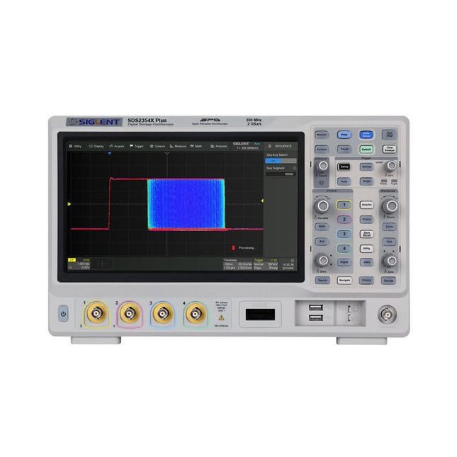
Siglent Siglent SDS2354X Plus 4-ch Oscilloscope (350 MHz)
Siglent's SDS2000X Plus series Digital Storage Oscilloscopes are available in bandwidths of 100 MHz, 200 MHz, and 350 MHz, have a maximum sample rate of 2 GSa/s, a maximum record length of 200 Mpts/ch, and up to 4 analog channels + 16 digital channels mixed-signal analysis ability. The SDS2000X Plus series employs Siglent’s SPO technology with a maximum waveform capture rate of up to 120,000 wfm/s (normal mode, up to 500,000 wfm/s in Sequence mode), 256-level intensity grading display function plus a color temperature display mode. It also employs an innovative digital trigger system with high sensitivity and low jitter. The trigger system supports multiple powerful triggering modes including serial bus triggering. History waveform recording, Sequence acquisition, Search and Navigate functions allow for extended waveform records to be captured, stored, and analyzed. An impressive array of measurement and math capabilities, options for a 50 MHz waveform generator, as well as serial decoding, mask test, bode plot, and power analysis are also features of the SDS2000X Plus. A 10-bit acquisition mode helps to satisfy applications that require more than 8-bit resolution. The large 10.1’’ capacitive touch screen supports multi-touch gestures, while the remote web control, mouse and external keyboard support greatly improve the operating efficiency of the SDS2000X Plus. Features 100 MHz, 200 MHz, 350 MHz (upgradable to 500 MHz) models Real-time sampling rate up to 2 GSa/s Record length up to 200 Mpts Serial bus triggering and decoder, supports I²C, SPI, UART, CAN, LIN, CAN FD, FlexRay, I²S and MIL-STD-1553B Provide 10 bit mode, Vertical and Horizontal Zoom Capacitive touch screen supports multi-touch gestures Siglent SDS2000X Plus Oscilloscopes SDS2102X Plus SDS2104X Plus SDS2204X Plus SDS2354X Plus Bandwidth 100 MHz 100 MHz 200 MHz 350 MHz Channels 2 4 4 4 Real-time sampling rate 2 GSa/s 2 GSa/s 2 GSa/s 2 GSa/s Capture rate 120,000 wfm/s 120,000 wfm/s 120,000 wfm/s 120,000 wfm/s Memory depth 200 Mpts/ch 200 Mpts/ch 200 Mpts/ch 200 Mpts/ch Included Siglent SDS2354X Plus Oscilloscope Passive probes Power cord USB cable Manual Downloads Datasheet Manual Quick guide User manual Firmware
€ 2.515,83
-

Elektor Digital Elektor Circuit Special 2026 (PDF) DE
Diese Ausgabe steht allen GOLD- und GREEN-Mitgliedern auf der ElektorMagazine-Website zum Download bereit! Sie sind noch kein Mitglied? Hier klicken! Stromquelle zum Testen von (Z-)DiodenPrüfen von Z-Dioden von 1 bis 54 V bei 1 bis 50 mA ESD-Armband-TesterEin Tool zur Funktionsprüfung von Erdungsarmbändern Transientenmesser für LabornetzteileEin reproduzierbarer Lastsprung-Generator für Labornetzteile 3D-Viewer für HTML-SeitenEinfach und fast ohne Code LED-Blinkleuchte für Tore und mehr mit akustischem Alarm Benötigen Sie Leiterplatten? Der Elektor-Leiterplattenservice ist für Sie da. Zahnbürsten-TimerMit einem kleinen PIC Ein berührungsloses magnetisches Kombinationsschlossmit dem AS5600-Drehpositionssensor Rauscharmer, batteriebetriebener Vorverstärkerfür dynamische Mikrofone Das Arduino Nano TestLabMessen, Steuern, Regeln Rhythmische BassleuchteBetonen Sie den Rhythmus Ihrer Musik Low-cut-FilterKein Risiko von Audio-Rückkopplungen in Ihrem System Präziser 1-Hz-Rechteckwellengenerator für SteckbrettEine zuverlässige CMOS-basierte Taktquelle 555 auf den Kopf gestelltTastverhältnisse bis hinunter auf Null Vom „Halfgeleidergids“ zu Circuit Specials65 Jahre Elektronik-Innovation Galvanische TrennungCAN-Schnittstelle mit Digitalisolator und Powermodul SpongillatorEin schwammbasierter Oszillator Echter Zufallszahlengeneratormit integriertem Chi-Quadrat-Test Euklidischer Sequencer ohne MikrocontrollerTrigger-Pattern und CV-Sequenzen mit einfacher CMOS-Logik Programmieren mit TLScriptEine Skriptsprache zum Messen, Testen und Steuern Schaltungsdesign: Tipps von Experten RückkopplungWas ist das und warum ist sie wichtig? Ein Board, endlose Ideen: Arduino UNO QVon Retro-Gaming zur Echtzeit-Umweltüberwachung So bringen Sie eine Donut-Antenne in Ordnung Standby-KillerEin echter Ein-/Ausschalter für den Fernseher Akkus im TestAkkus vermessen mit dem Arduino Nano Stromversorgung für Audio-EndstufenEin gutes Netzteil ohne Netzbrummen Lochrasterplatinen für HFSchnelle Aufbauten mit DIY-Prototyping-Boards T3-ÜberspannungsschutzEin Typ-3-Schutzmodul für empfindliche Geräte IoT-Raumthermostat-Platinemit dem Xiao-MCU-Modul auf Basis des ESP32-C3/S3 Von starr zu smartFlexible und gedruckte Elektronik – zwischen Vision und industrieller Realität
€ 11,90
-

Elektor Digital Programming with STM32 Nucleo Boards (E-book)
STM32 Nucleo family of processors are manufactured by STMicroelectronics. These are low-cost ARM microcontroller development boards. This book is about developing projects using the popular Nucleo development board. In the early chapters of the book, the architecture of the Nucleo family is briefly described. Software development tools that can be used with the Nucleo boards such as the Mbed, Keil MDK, TrueSTUDIO, and the System Workbench are described briefly in later Chapters. The book covers many projects using most features of the STM32 Nucleo development boards where the full software listings for Mbed and System Workbench are given for every project. The projects range from simple flashing LEDs to more complex projects using modules and devices such as GPIO, ADC, DAC, I²C, LCD, analog inputs and others. In addition, several projects are given using the Nucleo Expansion Boards, including popular expansion boards such as solid-state relay, MEMS and environmental sensors, DC motor driver, Wi-Fi, and stepper motor driver. These Expansion Boards plug on top of the Nucleo development boards and simplify the task of project development considerably. Features of this book Learn the architecture of the STM32 microcontrollers Learn how to use the Nucleo development board in projects using Mbed and System Workbench Toolchains Learn how to use the Nucleo Expansion Boards with the Nucleo development boards Update The Mbed compiler has been replaced with two software packages: The Mbed Studio and Keil Studio Cloud. Both of these software packages are free of charge and are available on the Internet. If you need assistance using the Keil Studio Cloud, please download the Guide below.
€ 34,95
Leden: € 31,46


