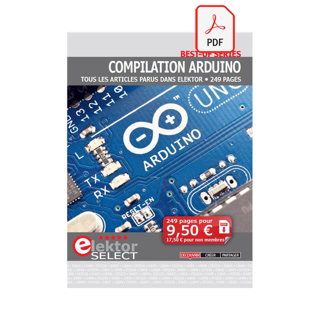
Cette compilation comprend des articles intégrés de l'actuel Elektor entre juillet 2012 et novembre 2014.
Les documents suivants sont inclus dans le numéro de document (PDF) avec la fonction de navigation disponible et les articles sont intéressants.
Voor thuis en op school
Dit boekje is gericht op leerlingen en natuurkunde docenten in het voortgezet onderwijs. Met voorbeelden op verschillende gebieden van de fysica, geeft het aan hoe een populair microprocessor platform als Arduino toegepast kan worden in het natuurkunde practicum. We passen Arduino onder andere toe als nauwkeurig meetinstrument, zodat metingen uitgewerkt kunnen worden in een spread sheet.
Hoewel enige handigheid niet overbodig is, kunnen de beschreven experimenten kunnen ook uitstekend thuis worden uitgevoerd. In dat opzicht wil dit boek met name bij de jeugd de interesse wekken voor de toepassing van microprocessoren. In de hobbysfeer is dat niet alleen een zinvolle tijdsbesteding, maar bovenal interessant en leuk.
Veiligheid staat uiteraard voorop bij het doen van experimenten. Energie, licht en warmte zijn onuitputtelijke bronnen, maar ze kunnen ook gevaar opleveren. Voor dit boek geldt dan ook het motto: Eerst denken, dan doen.
De Joy-Pi Advanced is een compact en krachtig instrument waarmee je snel en eenvoudig je projecten kunt realiseren. Of je nu veel of weinig ervaring hebt, met de Joy-Pi Advanced kun je je creativiteit de vrije loop laten. Dankzij de compatibiliteit met een groot aantal platformen, waaronder Raspberry Pi, Raspberry Pi Pico, Arduino Nano, BBC micro:bit en NodeMCU ESP32, kun je eenvoudig en snel toegang krijgen tot het platform van je voorkeur.
Daarnaast heeft de Joy-Pi Advanced meer dan 30 stations, lessen en modules, waardoor je een onbeperkt aantal manieren hebt om je projecten uit te voeren. Met het zelfontwikkelde leercentrum kun je niet alleen je vaardigheden verbeteren, maar ook nieuwe projecten maken. Het leercentrum biedt een schat aan informatie en tutorials die je stap voor stap door je projecten begeleiden.
Joy-Pi Advanced wordt in het bijzonder gekenmerkt door zijn intelligente schakeleenheden, die een uitgebreid gebruik van de beschikbare pinnen mogelijk maken. In totaal zijn er drie schakeleenheden geïntegreerd, elk voorzien van 12 individuele schakelaars die zorgen voor een nauwkeurige aansturing van de aangesloten sensoren en modules. Dit systeem lost het bekende probleem van het beperkte aantal pinnen op dat optreedt bij conventionele microcontrollers. Met de schakeleenheden kun je een groot aantal sensoren en modules parallel aansturen door ze afzonderlijk aan en uit te schakelen. Dit simuleert meervoudige pintoewijzing, waardoor je het volledige vermogen van je projecten kunt benutten zonder afbreuk te doen aan de functionaliteit.
Door onze innovatieve adapter boards en het micro:bit slot te combineren, bereiken we naadloze compatibiliteit met een breed scala aan microcontrollers zoals Raspberry Pi Pico, NodeMCU ESP32, micro:mit en Arduino Nano. De speciaal ontwikkelde adapterkaarten zijn zo ontworpen dat ze perfect passen bij de betreffende microcontroller. Door de microcontroller op het juiste adapterboard aan te sluiten en deze vervolgens in het micro:bit slot te steken, wordt de Joy-Pi Advanced snel en eenvoudig compatibel met de verschillende microcontrollers. Dit zorgt voor een naadloze integratie van het platform van je voorkeur en de mogelijkheid om de sterke punten van de verschillende microcontrollers te combineren in je projecten. Op deze manier kun je je volledig richten op je creatieve projecten zonder dat je je zorgen hoeft te maken over de compatibiliteit van verschillende microcontrollers. De Joy-Pi Advanced vereenvoudigt het ontwikkelproces en geeft je de mogelijkheid om je projecten flexibel en individueel te ontwerpen.
Kenmerken
Sterk geïntegreerd ontwikkelplatform & leercentrum
Snel, eenvoudig & draadloos combineren van verschillende sensoren & actuatoren
Installatieoptie voor Raspberry Pi 4
Compatibel met verschillende microcontrollers
Zelfontwikkeld, didactisch leerplatform voor Raspberry Pi & Windows
Specificaties
Compatibel met
Raspberry Pi 4, Arduino Nano, NodeMCU ESP32, BBC micro:bit, Raspberry Pi Pico
Geïnstalleerde sensoren, actuatoren & componenten
39
Leerplatform
Meer dan 40 items in de kennisdatabase, 10 projecten, 10 lessen, 14 visies
Displays
7-segment display, 16x2 display, 1,8' TFT-display, 0,96" OLED-display, 8x8 RGB-matrix
Sensoren
DS18B20, schoksensor, hallsensor, barometer, geluidssensor, gyroscoop, PIR-sensor, Lichtbarrière, NTC, Lichtsensor, 6x aanraaksensor, kleurensensor, ultrasone afstandssensor, DHT11 temperatuur- & vochtigheidssensor
Controle
Joystick, 5x schakelaars, potentiometer, draaiencoder, 4x4 knoppenmatrix, relais, PWM-ventilator
Motoren
Servo-interface, Stappenmotorinterface, Trilmotor
Meet- en conversiemodules
Analoog-digitaalomzetter, niveauomzetter, voltmeter, variabele spanningsbron
Andere onderdelen
RTC real-time klok, zoemer, EEPROM-geheugen, infrarood ontvanger, breadboard, RFID-lezer
Adapterkaarten
Adapter voor NodeMCU ESP32, Arduino Nano & Raspberry Pi Pico, Board connectors voor Raspberry Pi & externe boards
Elektronische onderdelen
Infrarood afstandsbediening, RFID-chip, RFID-kaart, 6x krokodillenklemmen, microSD-kaartlezer, servomotor, stappenmotor, 32 GB microSD-kaart
Onderdelen
40x weerstanden, 3x groene LED's, 3x gele LED's, 3x rode LED's, 1x transistor, 5x knoppen, 1x potentiometer, 2x condensatoren
Andere accessoires
Schroevenassortiment, schroevendraaier, accessoire-opbergtas, voeding & voedingskabel, servo bevestiging
Stroomvoorziening
Ingebouwde voeding: 36 W, 12 V, 3 A Behuizingsconnector: Kleine apparaat stekker C8
Spanningsuitgangen
12 V, 5 V, 3,3 V, variabele spanningsuitgang (2-11 V)
Databussen & signaaluitgangen
I²C, SPI, Analoog naar digitaal converter
Batterij (RTC)
CR2032
Afmetingen
327 x 200 x 52 mm
Inbegrepen
Raspberry Pi 4 (8 GB RAM)
Downloads
Joy-Pi website
Datasheet
Manual
Concrétisez vos rêves, réalisez les projets les plus fous : un odomètre pour la roue de votre hamster, la surveillance complètement automatisée de votre fourmilière avec interface web, ou le Sandwich-O-Mat – une machine qui grille les sandwichs de votre choix.Avec les cartes Arduino et le mouvement DIY (« fais-le toi-même ») ou maker, se mettre à programmer des microcontrôleurs est devenu un jeu d'enfant. Une deuxième révolution a eu lieu : des développeurs ingénieux ont mis sur le marché de petites cartes – appelées « shields » ou modules – qui simplifient considérablement l'utilisation d'autres dispositifs. Ces petits modules contiennent tous les composants électroniques nécessaires pour la connexion au microcontrôleur ; quelques fils avec des fiches suffisent pour le raccordement, ce qui évite d'avoir à câbler et fait gagner du temps. En outre, il est également possible de manipuler de minuscules composants dépourvus de pattes de connexion (ceux de type CMS).ProjetsArduino et le monde extérieurCapteur BMP180, introduction aux bibliothèques et à l'I²CInitiation aux entrées/sorties avec un shield polyvalentAdaptateur I²C pour LCD et afficheurs à matrice de pointsShield clavier & LCDConvertisseur de niveauW5100 : connexion à internetShields d'extension des entrées/sortiesRelais et relais statiquesShield multifonction : unité de commande universelleConnexion d'un lecteur de carte SD par SPITouches et afficheurs à 7 segmentsConvertisseur analogique/numérique à 16 bitsConvertisseur numérique/analogique MCP4725Pilote de servomoteurs à 16 voies PWMLecteur MP3Enregistreur de données GPS avec stockage sur carte SDCapteur tactileJoystickSHT31 : température et humiditéCapteur d'UV-A VEML6070Temps de vol VL53L0XMesure de distance à ultrasonsAfficheur matriciel à LED à base de MAX7219Horloge en temps réel DS3231Circuit d'extension de port MCP23017Communication radio à 433 MHzGyroscope MPU-6050Accéléromètre ADXL345LED RVB WS2812Cartes d'alimentationCapteurs de gaz MQ-xxCapteur de dioxyde de carbone (CO2)Capteur de courant ACS712Capteur de courant INA219Pilote de moteur L298Kit RFID MFRC522Moteur pas à pas 28BYJ-48Carte avec pilote de moteur ultra-silencieux TMC2209Potentiomètre numérique X9C10xÉcran couleur TFT avec contrôleur/pilote ST7735Écran à encre électroniqueModule BluetoothCompteur GeigerModule GSM SIM800LMultiplexeur I²CModule CAN (Controller Area Network)
De OWON SDS1102 is een betaalbare benchtop digitale oscilloscoop die solide prestaties combineert met essentiële meetfuncties. Deze 2-kanaals oscilloscoop biedt een bandbreedte van 100 MHz, een sample rate van 1 GS/s, een 7-inch LCD-display en een geheugendiepte van 10 kpts. Daarmee is het een praktische keuze voor dagelijkse elektronicatests, foutopsporing en onderwijs.
De SDS1102 beschikt over een vereenvoudigd triggersysteem met niveau- en flanktriggering, waardoor gangbare signalen eenvoudig kunnen worden vastgelegd en geanalyseerd. Het apparaat is ontworpen voor toepassingen waarvoor geen grote geheugendiepte of geavanceerde triggerfuncties nodig zijn, en biedt een eenvoudige en kostenefficiënte oplossing voor basis-signaalanalyse.
Kenmerken
Bandbreedte: 100 MHz
2 kanalen
Bemonsteringssnelheid: 1 GS/s
Ultradunne behuizing
7-inch lcd met hoge resolutie
Ondersteuning voor SCPI en LabVIEW
Specificaties
Bandbreedte
100 MHz
Horizontale schaal (s/div)
5 ns/div - 1000 s/div
Kanalen
2
Verticale gevoeligheid
5 mV/div - 5 V/div (bij ingang)
DC Gain nauwkeurigheid
3%
Verticale resolutie (A/D)
8 bits (2 kanalen tegelijk)
Ingang
Ingangsimpedantie
1 MΩ, 10 pF
Ingangskoppeling
AC, DC, GND
Max ingangsspanning
± 400 V, CATI, CATII
Passieve probes
x1; 10
Probe verzwakkingsfactor
x1; x10; x100; x1000
Triggersysteem
Trigger mode
Auto, Normal, Single
Trigger type
Flank, Video
Flank triggerbron
CH1, CH2
Video trigger
Sampletype
Real-time
Samplefrequentie
1 GS/s
Equivalente samplesnelheid
No
Golflengte
10K pts
Interpolatie
sin(x)/x
Meet- en rekenkundig bewerkingssysteem
Automatische meting
Vpp, Vavg, RMS, Frequency, Period, Vmax, Vmin, Vtop, Vbase, Width, Overshoot, Pre-shoot Rise time, Fall time, +Width, -Width, +Duty, -Duty, Delay A->B, Delay A->B, area, cycle area
Rekenkundige functies
Addition, Subtraction, Multiplication, Division, FFT
Algemene kenmerken
Display maat
7" color LCD
Display resolutie
800 x 480
Voeding
100-240 V, 45-440 Hz, <15 W
Afmetingen
301 x 70 x 152 mm
Gewicht
1,1 kg
Inbegrepen
1x OWON SDS1102 Oscilloscoop
2x Oscilloscoopsonde
1x Sonde aanpassen
1x Netsnoer
1x USB-kabel
1x CD-Rom
1x Snelstartgids
Downloads
Quick Guide
Manual
PC Software
SCPI Commands
The Piccolino rapid development board can be used to design microcontroller circuits quickly. The Piccolino has a fast 16f887 PIC microcontroller, voltage regulator, and communications module, and can be easily extended using its four headers.
This e-book contains 30 projects based on the Piccolino. We'll use its unique communications facilities and get the Piccolino to communicate with programs on a PC. On the PC, we use the free programming language Small Basic. You can use this to create Windows programs with buttons and graphs quickly. You will learn how to analyze components such as inductors, capacitors, and OPAMPs, and how to display the measurement results in a graphical format. This will help you to design your circuits easily.
We will then start to adapt to the Piccolino. We'll add components to it to make it more powerful, with extra features such as flow control and digital to analog conversion. The clear instructions will enable you to design and build your adaptations. This way you can make your custom designed Piccolino.
We'll end up making an extension: a PCB that that can be mounted on the Piccolino headers. As an example, we'll design and build an extension for an LCD. You can use the included board layout to make your PCB or have it made for you. At the same time, you will learn how to make your extensions. The only limitation is your imagination!
The clear descriptions along with circuit diagrams and photos, will make the building of these projects an enjoyable experience. Each project has a clear explanation of the reasons why it was designed in a particular way. This helps you learn a lot about the Piccolino, as well as Small Basic, and the components that are used in this e-book. You can adapt the projects to suit your requirements or combine several projects.
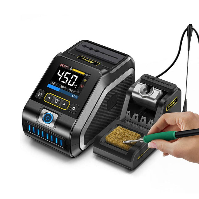
De FNIRSI DWS-200 is een krachtig 200 W slim soldeerstation, ideaal voor elektronische soldeertoepassingen. Hij wordt gevoed door een schakelende voeding en werkt soepel met een breed spanningsingangsbereik van 100-240 V. Het station biedt een instelbaar temperatuurbereik van 100°C tot 450°C en maakt eenvoudig schakelen tussen °C en °F mogelijk.
Om de efficiëntie te verbeteren, ondersteunt het maximaal drie vooraf ingestelde temperatuurwaarden en kan het worden aangesloten op een soldeerboutstandaard voor activering van de standby-modus. Het station beschikt ook over een dynamische temperatuurcurvemodus voor realtime gegevensbewaking, waardoor nauwkeurige en consistente prestaties bij veeleisende soldeertaken worden gegarandeerd.
Kenmerken
Maximaal uitgangsvermogen van 200 W, waardoor snelle verwarming mogelijk is
Brede adaptieve spanningsingang van 100-240 V
2,8" HD-TFT-kleurenscherm met intelligente bediening
Meerdere vooraf ingestelde groepen om snel tussen verschillende instellingen te schakelen
Ondersteunt de typen soldeerhandgrepen F245 en F210 en biedt flexibiliteit voor verschillende soldeertoepassingen
Realtime slaapmodus om de levensduur van de soldeerpunt te verlengen
Multi-mode real-time monitoring van de stroom- en temperatuurstatus, waardoor de veiligheid en precisie worden verbeterd
Specificaties
Piekvermogen
200 W (max)
Temperatuurbereik
100°C~450°C
Display
2,8" TFT HD-kleurenscherm
Verwarmingstijd
1 seconde
Smelttijd
3 seconden
Ingangsspanning
100-240 V (AC)
Ingangszekering
3 A
Type soldeergreep
F245
Afmetingen (station)
156 x 96 x 103 mm
Gewicht (station)
475 g
Inbegrepen
1x FNIRSI DWS-200 soldeerstation
1x Soldeerhandgreep F245
6x Soldeertips (B, KU, K, C2, I, JS)
1x Verbindingskabel
2x Helpende handen
1x Voedingskabel (EU)
Downloads
Manual
Firmware V1.3
Bouw je eigen vintage radiozender
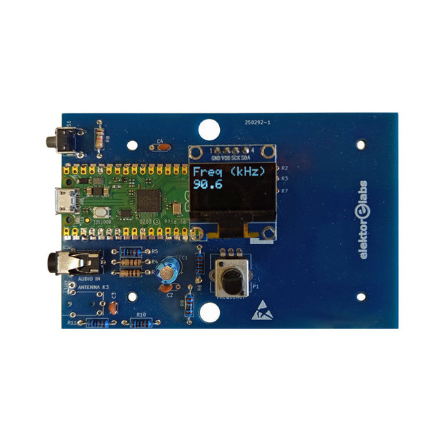
De Elektor AM-zender kit maakt het mogelijk om audio te streamen naar vintage AM-radiotoestellen. Gebaseerd op een Raspberry Pi Pico microcontroller-module kan de AM-zender uitzenden op 32 frequenties in de AM-band, van 500 kHz tot 1,6 MHz in 32 stappen van ca. 35 kHz.
De frequentie wordt gekozen met een potentiometer en weergegeven op een 0,96" OLED-display. Een drukknop maakt het mogelijk om de zendmodus te schakelen tussen Aan en Uit. Het bereik van de zender hangt af van de antenne. De ingebouwde antenne biedt een bereik van enkele centimeters, waardoor de AM-zender dicht bij of in de radio moet worden geplaatst. Een externe lusantenne (niet inbegrepen) kan worden aangesloten om het bereik te vergroten.
De Elektor AM-zender kit wordt geleverd als een bouwpakket dat je zelf op de printplaat moet solderen.
Kenmerken
De printplaat is compatibel met een Hammond 1593N-behuizing (niet inbegrepen).Een 5 VDC-voeding met micro-USB-connector (bijv. een oude telefoonoplader) is nodig om de kit van stroom te voorzien (niet inbegrepen). Stroomverbruik: 100 mA.
De Arduino-software (vereist het RP2040-boards-pakket van Earle Philhower) voor de Elektor AM-zenderkit plus meer informatie is beschikbaar op de Elektor Labs-pagina van dit project.
Componentenlijst
Weerstanden
R1, R4 = 100 Ω
R2, R3, R8 = 10 kΩ
R5, R6, R9, R10, R11 = 1 kΩ
R7 = optioneel (niet inbegrepen)
P1 = potentiometer 100 kΩ, lineair
Condensatoren
C1 = 22 µF 16V
C2, C4 = 10 nF
C3 = 150 pF
Diversen
K1 = 4×1 pinheader
K2, K3 = 3,5 mm-aansluiting
Raspberry Pi Pico
Drukknop, haaks gemonteerd
0,96" monochroom I²C OLED-display
PCB 150292-1
The XIAO ESP32-C3 board combines the ultra-compact form factor of the XIAO series with the full capabilities of the ESP32-C3 chip, including integrated Wi-Fi and Bluetooth 5.0. This book is a comprehensive, hands-on guide to getting the most out of this powerful yet affordable development board.
The author takes readers from the fundamentals to advanced projects. Starting with LED blinking and dimming, the book progresses to ADC and PWM for precise sensor interfacing and PWM-controlled lighting effects before moving on to building practical, real-world applications, including:
A Wi-Fi weather station with an OLED display and real-time online weather data
An ultrasonic parking assistant with audible feedback
A refrigerator monitoring probe with climate sensing and Deep Sleep for years of battery operation
A retro Pong game controlled by a touch-free sensor
A microphone-based party app that responds to claps
And much more: lighting control, reaction-time measurement, mains frequency analysis, soil moisture sensing, ambient LED lighting, and 7-segment displays
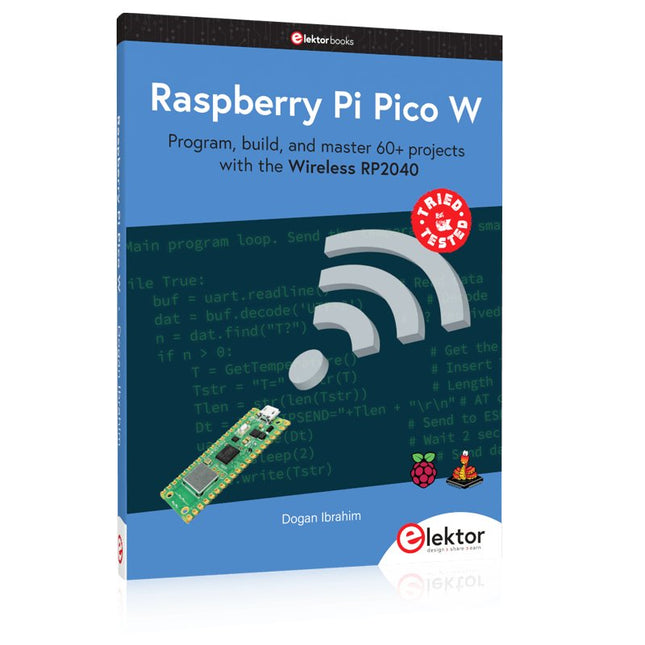
Program, build, and master 60+ projects with the Wireless RP2040
The Raspberry Pi Pico and Pico W are based on the fast, efficient, and low-cost dual-core ARM Cortex M0+ RP2040 microcontroller chip running at up to 133 MHz and sporting 264 KB of SRAM and 2 MB of Flash memory. Besides spacious memory, the Pico and Pico W offer many GPIO pins, and popular peripheral interface modules like ADC, SPI, I²C, UART, PWM, timing modules, a hardware debug interface, and an internal temperature sensor.
The Raspberry Pi Pico W additionally includes an on-board Infineon CYW43439 Bluetooth and Wi-Fi chipset. At the time of writing this book, the Bluetooth firmware was not yet available. Wi-Fi is however fully supported at 2.4 GHz using the 802.11b/g/n protocols.
This book is an introduction to using the Raspberry Pi Pico W in conjunction with the MicroPython programming language. The Thonny development environment (IDE) is used in all of the 60+ working and tested projects covering the following topics:
Installing the MicroPython on Raspberry Pi Pico using a Raspberry Pi or a PC
Timer interrupts and external interrupts
Analogue-to-digital converter (ADC) projects
Using the internal temperature sensor and external sensor chips
Using the internal temperature sensor and external temperature sensor chips
Datalogging projects
PWM, UART, I²C, and SPI projects
Using Bluetooth, WiFi, and apps to communicate with smartphones
Digital-to-analogue converter (DAC) projects
All projects are tried & tested. They can be implemented on both the Raspberry Pi Pico and Raspberry Pi Pico W, although the Wi-Fi-based subjects will run on the Pico W only. Basic programming and electronics experience are required to follow the projects. Brief descriptions, block diagrams, detailed circuit diagrams, and full MicroPython program listings are given for all projects.
Dieses E-Book enthält 53 originale Arduino-Artikel, die in der Zeitschrift Elektor zwischen März 2009 und Juli/August 2015 veröffentlicht wurden.
Das 268 Seiten umfassende PDF steckt voller Ideen, Erklärungen, Tipps, Grafiken, Programme, Platinenlayouts und vieles mehr. Die Artikel sind informativ, unterhaltsam und anregend zugleich. Lassen Sie sich inspirieren!
Das Inhaltsverzeichnis ist komplett verlinkt, so dass Sie Ihr gewünschtes Projekt sofort öffnen und lesen oder auch zwischen den Projekten schnell wechseln können.
PC USB Logic Analyzers with Arduino, Raspberry Pi, and Co.
Step-by-step instructions guide you through the analysis of modern protocols such as I²C, SPI, UART, RS-232, NeoPixel, WS28xx, HD44780 and 1-Wire. With the help of numerous experimental circuits based on the Raspberry Pi Pico, Arduino Uno and the Bus Pirate, you will learn the practical application of popular USB logic analyzers.
All the experimental circuits presented in this book have been fully tested and are fully functional. The necessary program listings are included – no special programming or electronics knowledge is required for these circuits. The programming languages used are MicroPython and C along with the development environments Thonny and Arduino IDE.
This book uses several models of flexible and widely available USB logic analyzers and shows the strengths and weaknesses of each price range.
You will learn about the criteria that matter for your work and be able to find the right device for you.
Whether Arduino, Raspberry Pi or Raspberry Pi Pico, the example circuits shown allow you to get started quickly with protocol analysis and can also serve as a basis for your own experiments.
After reading this book, you will be familiar with all the important terms and contexts, conduct your own experiments, analyze protocols independently, culminating in a comprehensive knowledge set of digital signals and protocols.