Zoekresultaten voor "greatfet OR one"
-

Great Scott Gadgets Acryl behuizing voor HackRF One/Pro SDR
Deze doorzichtige acryl behuizing is de officiële behuizing voor het HackRF One/Pro board. Hij kan de standaard zwarte plastic behuizing van de HackRF One/Pro vervangen. Montage-instructies Gebruik een plectrum of spudger om de HackRF One/Pro printplaat uit de zwarte plastic behuizing te halen. Steek een lange schroef in elke hoek van het onderste acrylpaneel. Zet elke lange schroef vast met een kort afstandsstuk (5 mm) aan de tegenoverliggende kant van het paneel. Plaats de HackRF One/Pro printplaat (naar boven gericht) bovenop het onderpaneel en steek de uiteinden van de lange schroeven door de bevestigingsgaten in de hoeken van de print. Zet de printplaat vast met een lang afstandsstuk (6 mm) in elke hoek. Plaats het bovenste acrylpaneel op de printplaat en lijn de uitsparingen uit met de extension headers op de print. Zet elke hoek vast met een korte schroef. Opmerking: Niet te strak aandraaien! Na elke stap alleen met de hand aandraaien.
€ 19,95
Leden € 17,96
-

Elektor Labs Elektor Eénarmige Bandiet
Trek de hendel naar beneden voor de hoogste score!Deze Elektor Circuit Classic uit 1984 toont een speelse toepassing van logische IC's uit de CMOS 400x serie in combinatie met leds, destijds een zeer populaire combinatie. Het project imiteert een gokkast met ronddraaiende cijfers.Het spelVoordat het spel start dient u eerst het aantal rondes af te spreken. Speler 1 trekt de schakelhendel naar beneden zo lang als hij wenst en laat hem dan los. De leds tonen vervolgens de score die de som is van de 20-10-5-2-1 leds die oplichten. Mocht het Play Again! ledje gaan branden dan heeft speler 1 een extra 'gratis' ronde. Zo niet, dan is speler 2 aan de beurt. De spelers houden hun scores bij en de hoogste score wint.Kenmerken Leds geven de score aan Meerdere spelers en Play Again! Elektor Heritage circuit symbolen Uitgeprobeerd en getest door Elektor Labs Educatief en nerdy project Through-hole onderdelen Inbegrepen Printplaat Alle componenten Houten standaard Stuklijst Weerstanden (5%, 250 mW) R1, R2, R3, R4 = 100 kΩ R5, R6, R7, R8, R9, R10 = 1 kΩ Condensatoren C1 = 4,7 nF, 10 %, 50 V, 5 mm C2 = 4,7 μF, 10%, 63 V, axiale C3, C4 = 100 nF, 10 %, 50 V, keramiek X7R, 5 mm Halfgeleiders Led1 – Led6 = rood, 5 mm (T1 3/4) IC1 = 74HC4024 IC2 = 74HC132 Diversen S1 = schakelaar, tuimel, 21 mm hendel, SPDT, kortstondig S2 = schakelaar, tactiel, 24 V, 50 mA, 6x6 mm S3 = schakelaar, schuif, SPDT IC1, IC2 = IC-voetje, DIP14 BT1 = CR2032 PCB batterijhoudertje Tafel standaard PCB 230098-1 Niet inbegrepen: BT1 = CR2032 knoopcel batterij
€ 39,95€ 15,98
Leden identiek
-

Elektor Digital Elektor Juli/Augustus 2020 (PDF)
ELEKTOR AIDE L'électronique dans des temps difficiles AFFICHAGE D'INFORMATION POUR LA MAISON avec Windows sur le Raspberry Pi DÉMARRER AVEC NODE-RED un outil de programmation open source basé sur des blocs visuels LA tombola d'ÉTÉ d'ELEKTOR GREATSCOTT ! CONSTRUIRE UN SYSTÈME D'ALARME LORA REVUE : ALIMENTATION DE LABORATOIRE JOY-IT RD6006 (KIT) REVUE : INTERFACEBOARD GREATFET ONE QUI N'HONNE PAS LES PETITS – XXL de la boîte à suggestions d'Elektor ANTENNE WIFI EXTERNE 2,4 GHZ POORLUIS CONTRÔLE FACILE DE LA TEMPÉRATURE MARCHE/ARRÊT AVEC CHAPEAU RASPBERRY PI COMMENT PRENDRE DE (BONNES) PHOTOS DÈS L'IMPRESSION... ...et les composants électroniques ? REVUE : NOYAU I2CDRIVER ÉCRAN TACTILE JOY-VIEW 13 DE JOY-IT BOOSTER LED POUR MICROCONTRÔLEURS avec un seul composant ! MACHINE À LAVER À ULTRASONS EXPÉRIMENTALE REVUE : GÉNÉRATEUR DE SIGNAUX JOY-IT JDS2915 générateur de signaux doubles avec compteur de fréquence dans un boîtier métallique PROGRAMMATION DES FEUX DE SIGNALISATION EN LANGAGE PIC ASSEMBLY LED CLIGNOTANT PERMANENT CAPTEUR DE HALL EXPÉRIMENTAL DÉTECTER LES COURT-CIRCUITS AVEC UN MILLIOHM OU ESR MÈTRE KIT PRATIQUE ÉLECTRIQUE SDR PIPELINE DE LABORATOIRES ÉLECTRIQUES KICK-STARTER ÉLECTRIQUE ....eh bien, vous voyez ce que nous voulons dire. AVEZ-VOUS VRAIMENT BESOIN DE TOUT ÇA ??? ici, je passe de nombreuses heures sur des projets électroniques... LABORATOIRE EST OUEST MEILLEUR un aperçu du plus saint des saints, où naissent des projets intéressants BONJOUR LE MONDE! NOUS SOMMES ELEKTOR ET NOUS SOMMES SOCIAUX M4 + A7 + GPU : UNE ÉQUIPE DE RÊVE INÉGALE le nouveau SoC STM32MP1 pour les travaux plus lourds CONFIGURATION DE TEST POUR LE 16F18877 ET AUTRES GRANDES PHOTOS COMMUNICATION INTER-ΜC AVEC LE BUS SPI ET ATMEGA328P SIX VARIANTES DE L'OSCILLATEUR LF/AF (et la capacité de M. Miller) BBC MICRO:BIT oscilloscope absolument minimaliste avec affichage LED FEU DE RUNNING À LED 'KNIGHT RIDER' AVEC ESP32 GÉNÉRATEUR DE SIGNAUX AM LW/MW AVEC ATTINY13 DIPMÈTRE ABSOLUMENT MINIMALISTE SCOOTERS ÉLECTRIQUES BON MARCHÉ quelle est la qualité d'un scooter électrique « homologué » à 300 euros de Lidl ? AIDE AU STATIONNEMENT À ULTRASONS AVEC ARDUINO UNO PÉDALE DE DISTORSION AVEC AMPLI OP ET TUBES DE CHARGE SPATIALE INDISPENSABLE POUR CHAQUE LABORATOIRE D'ÉLECTRONIQUE HEXADOKU IA POUR DÉBUTANTS (2) réseaux de neurones avec Linux et Python
€ 9,95
-

Elektor Digital Oscilloscopes (E-book)
Understanding and Using Them Effectively What happens in electronics is invisible to the naked eye. The instrument that allows to accurately visualize electrical signals, the one through which the effects of electronics become apparent to us, is the oscilloscope. Alas, when one first ventures into electronics, it is often without an oscilloscope. And one is left fumbling, both physically and mentally. Observing an electrical signal on a screen for the first time is a revelation. Nobody wishes to forgo that marvel again. There is no turning back. In electronics, if one wishes to progress with both enjoyment and understanding, an oscilloscope is essential. This marks the beginning of a period of questioning: how to choose one? And no sooner is that question answered than a whole string of others arises, which can be summed up in just one: how does one use the oscilloscope in such a way that what it displays truly reflects the reality of the signals? Rémy Mallard is a passionate communicator with a gift for making complex technical subjects understandable and engaging. In this book, he provides clear answers to essential questions about using an oscilloscope and offers a wealth of guidance to help readers explore and understand the electrical signals behind electronic systems. With his accessible style and practical insights, this book is a valuable tool for anyone eager to deepen their understanding of electronics.
€ 34,95
Leden € 27,96
-

Elektor Publishing Oscilloscopes (Book)
Understanding and Using Them Effectively What happens in electronics is invisible to the naked eye. The instrument that allows to accurately visualize electrical signals, the one through which the effects of electronics become apparent to us, is the oscilloscope. Alas, when one first ventures into electronics, it is often without an oscilloscope. And one is left fumbling, both physically and mentally. Observing an electrical signal on a screen for the first time is a revelation. Nobody wishes to forgo that marvel again. There is no turning back. In electronics, if one wishes to progress with both enjoyment and understanding, an oscilloscope is essential. This marks the beginning of a period of questioning: how to choose one? And no sooner is that question answered than a whole string of others arises, which can be summed up in just one: how does one use the oscilloscope in such a way that what it displays truly reflects the reality of the signals? Rémy Mallard is a passionate communicator with a gift for making complex technical subjects understandable and engaging. In this book, he provides clear answers to essential questions about using an oscilloscope and offers a wealth of guidance to help readers explore and understand the electrical signals behind electronic systems. With his accessible style and practical insights, this book is a valuable tool for anyone eager to deepen their understanding of electronics.
€ 44,95
Leden € 40,46
-
Elektor Digital IoT Home Hacks with ESP8266 (E-book)
There are many so-called 'Arduino compatible' platforms on the market. The ESP8266 – in the form of the WeMos D1 Mini Pro – is one that really stands out. This device includes WiFi Internet access and the option of a flash file system using up to 16 MB of external flash memory. Furthermore, there are ample in/output pins (though only one analogue input), PWM, I²C, and one-wire. Needless to say, you are easily able to construct many small IoT devices! This book contains the following builds: A colourful smart home accessory refrigerator controller 230 V power monitor door lock monitor and some further spin-off devices. All builds are documented together with relevant background information for further study. For your convenience, there is a small PCB for most of the designs; you can also use a perf board. You don’t need to be an expert but the minimum recommended essentials include basic experience with a PC, software, and hardware, including the ability to surf the Internet and assemble PCBs. And of course: A handle was kept on development costs. All custom software for the IoT devices and PCB layouts are available for free download from at Elektor.com.
€ 34,95
Leden € 27,96
-

Elektor Digital Python 3 Programming and GUIs (E-book)
This is the second edition of a book aimed at engineers, scientists, and hobbyists who want to interface PCs with hardware projects using graphical user interfaces. Desktop and web-based applications are covered. The programming language used is Python 3, which is one of the most popular languages around: speed of programming being a key feature. The book has been revised and updated with an emphasis on getting the user to produce practical designs with ease – a text editor is all that is required to produce Python programs. Hardware interfacing is achieved using an Arduino Uno as a remote slave. A full description and source code of the communication interface is given in the book. The slave provides digital and analog input and outputs. Multiple Unos can be included in one project with all control code written in Python and running on a PC One project involves a PIC microcontroller with the code provided that can be loaded into the PIC using the Uno. The web applications and server are all implemented in Python, allowing you to access your electronic hardware over the Internet. The Raspberry Pi computer can be used as your web server. An introductory chapter is provided to get you started with using Linux. The book is written for use with Debian or variations including Mint or Ubuntu. All of the programs in the book are freely available, ready to use and experiment with by way of a download from Elektor.
€ 29,95
Leden € 23,96
-

Elektor Digital Vanderveen Trans Tube Amplifiers (E-book)
Menno van der Veen is well known for his research publications on tube amplifiers used in audio systems. In this book he describes one of his research projects which focuses on the question of whether full compensation for distortion in tubes and output transformers is possible. In the past, a variety of techniques have been developed. One of them has largely been forgotten: trans-conductance, which means converting current into voltage or voltage into current. Menno van der Veen has breathed new life into this technique with his research project titled “Trans”. This book discusses all aspects of this method and discusses its pitfalls. These pitfalls are addressed one by one. The end result is a set of stringent requirements for Trans amplifiers. Armed with these requirements, Menno then develops new Trans amplifiers, starting with Transie 1 and Transie 2. These DC-coupled, single-ended tube amplifiers have unusually good characteristics and are suitable for hobbyist construction. Next the Trans principle is applied to amplifiers with higher output power. A trial-and-error process ultimately leads to the Vanderveen Trans 30 amplifier, which optimizes the features of Trans. The characteristics of this amplifier are so special and unique that Menno believes he has struck gold. To ensure that variations in tube characteristics cannot interfere with optimal Trans behavior, Menno makes use of simulations and comparison with other amplifier types. This book reads like an adventure story, but it is much more – it is an account of solid research into new ways to achieve optimal audio reproduction.
€ 29,95
Leden € 23,96
-

Elektor Digital Controller Area Network Projects with ARM and Arduino (E-book)
This book details the use of the ARM Cortex-M family of processors and the Arduino Uno in practical CAN bus based projects. Inside, it gives a detailed introduction to the architecture of the Cortex-M family whilst providing examples of popular hardware and software development kits. Using these kits helps to simplify the embedded design cycle considerably and makes it easier to develop, debug, and test a CAN bus based project. The architecture of the highly popular ARM Cortex-M processor STM32F407VGT6 is described at a high level by considering its various modules. In addition, the use of the mikroC Pro for ARM and Arduino Uno CAN bus library of functions are described in detail. This book is written for students, for practising engineers, for hobbyists, and for everyone else who may need to learn more about the CAN bus and its applications. The book assumes that the reader has some knowledge of basic electronics. Knowledge of the C programming language will be useful in later chapters of the book, and familiarity with at least one microcontroller will be an advantage, especially if the reader intends to develop microcontroller based projects using CAN bus. The book should be useful source of reference to anyone interested in finding an answer to one or more of the following questions: What bus systems are available for the automotive industry? What are the principles of the CAN bus? What types of frames (or data packets) are available in a CAN bus system? How can errors be detected in a CAN bus system and how reliable is a CAN bus system? What types of CAN bus controllers are there? What are the advantages of the ARM Cortex-M microcontrollers? How can one create a CAN bus project using an ARM microcontroller? How can one create a CAN bus project using an Arduino microcontroller? How can one monitor data on the CAN bus?
€ 32,95
Leden € 26,36
-

Elektor Digital Retronics (E-book)
Quite unintentionally a one-page story on an old Heathkit tube tester in the December 2004 edition of Elektor magazine spawned dozens of ‘Retronics’ tales appearing with a monthly cadence, and attracting a steady flow of reader feedback and contributions to the series. Since launching his Retronics columns, Elektor Editor Jan Buiting has never been short of copy to print, or vintage equipment to marvel at. This book is a compilation of about 80 Retronics installments published between 2004 and 2012. The stories cover vintage test equipment, prehistoric computers, long forgotten components, and Elektor blockbuster projects, all aiming to make engineers smile, sit up, object, drool, or experience a whiff of nostalgia. To reflect that our memories are constantly playing tricks on us, and honoring that “one man’s rubbish is another man’s gem”, the tales in the book purposely have no chronological order, and no bias in favor of transistor or tube, microprocessor or discrete part, audio or RF, DIY or professional, dry or narrative style. Although vastly diff erent in subject matter, all tales in the book are told with personal gusto because Retronics is about sentiment in electronics engineering, construction and repair, be it to reminisce about a 1960s Tektronix scope with a cleaning lady as a feature, or a 1928 PanSanitor box for dubious medical use. Owners of this book are advised to not exceed one Retronics tale per working day, preferably consumed in the evening hours under lamp light, in a comfortable chair, with a piece of vintage electronic equipment close and powered up.
€ 24,95
Leden € 19,96
-
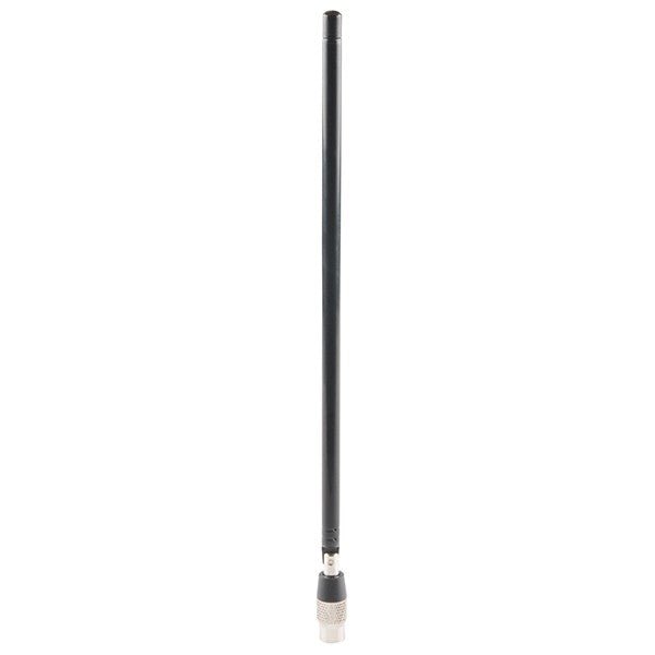
Great Scott Gadgets Great Scott Gadgets ANT500 Telescopische antenne (75 MHz – 1 GHz)
De ANT500 van Great Scott Gadgets is een telescopische antenne die is ontworpen voor gebruik tussen 75 MHz en 1 GHz. De totale lengte is instelbaar van 20 cm tot 88 cm. De ANT500 is gemaakt van roestvrij staal en heeft een SMA-mannelijke connector, een draaibare as en een verstelbare elleboog. De ANT500 is een 50 ohm antenne voor algemeen gebruik. Het is de perfecte eerste antenne voor gebruik met HackRF One/Pro.
€ 34,95
Leden € 31,46


-

, van Burkhard Kainka Review van de eerste ervaringen met HackRF One
Toen ik de HackRF One voor het eerst in mijn hand hield, wist ik er bijna niets van, behalve dat het een SDR ontvanger en...
