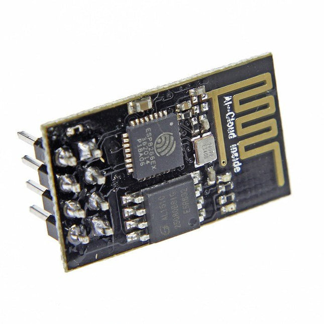
De ESP8266 is een indrukwekkende, goedkope WiFi module die geschikt is om WiFi functionaliteit toe te voegen aan een bestaand microcontroller project via een UART seriële verbinding. De module kan zelfs worden geherprogrammeerd om te fungeren als een standalone WiFi connected device – voeg gewoon stroom toe! 802.11 b/g/n protocol Wi-Fi Direct (P2P), soft-AP Geïntegreerde TCP/IP-protocolstack Deze module is een zelfstandige SOC (System On a Chip) die niet noodzakelijkerwijs een microcontroller nodig heeft om inputs en outputs te manipuleren zoals u normaal gesproken zou doen met bijvoorbeeld een Arduino, omdat de ESP-01 fungeert als een kleine computer. Je kunt dus een microcontroller internettoegang geven zoals het Wi-Fi shield doet bij de Arduino, of je kunt de ESP8266 gewoon programmeren om niet alleen toegang te hebben tot een Wi-Fi netwerk, maar ook te fungeren als een microcontroller, wat de ESP8266 zeer veelzijdig maakt.
Een retro-rol met een neonziel
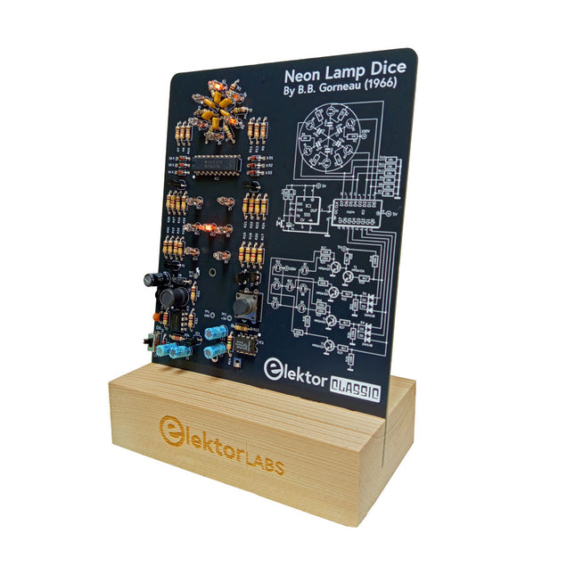
Dobbelstenen met leds zijn gebruikelijk, maar hun licht is koud. Dat geldt niet voor deze elektronische neon-dobbelsteen, die zijn waarde toont met de warme gloed van neonlampen. Hij is perfect om te spelen op koude, donkere winteravonden. De ogen van de dobbelsteen zijn neonlampen en de random number generator heeft zes neonlampen om aan te geven dat hij werkt.
Hoewel de dobbelsteen een ingebouwde 100 V-voeding heeft, is hij volkomen veilig. Zoals bij alle Elektor Classic-producten is ook bij de dobbelsteen het schema op de voorkant afgedrukt, terwijl een uitleg over de werking van de schakeling op de achterkant te vinden is.
De neonlamp-dobbelsteen wordt geleverd als een bouwpakket met eenvoudig te solderen doorlopende onderdelen. De voeding is een 9 V-batterij (niet meegeleverd).
Kenmerken
Warme vintage gloed
Elektor Heritage Circuit Symbolen
Getest en getest door Elektor Labs
Educatief en geeky project
Alleen doorlopende onderdelen
Inbegrepen
Printplaat
Alle componenten
Houten standaard
Vereist
9 V batterij
Stuklijst
Weerstanden (THT, 150 V, 0.25 W)
R1, R2, R3, R4, R5, R6, R14 = 1 MΩ
R7, R8, R9, R10, R11, R12 = 18 kΩ
R13, R15, R16, R17, R18, R21, R23, R24, R25, R26, R28, R30, R33 = 100 kΩ
R32, R34 = 1.2 kΩ
R19, R20, R22, R27, R29 = 4.7 kΩ
R31 = 1 Ω
Condensatoren
C1, C2, C3, C4, C5, C6 = 470 nF, 50 V, 5 mm pitch
C7, C9, C11, C12 = 1 µF, 16 V, 2 mm pitch
C8 = 470 pF, 50 V, 5 mm pitch
C10 = 1 µF, 250 V, 2.5 mm pitch
Spoelen
L1 = 470 µH
Halfgeleiders
D1, D2, D3, D4, D5, D6, D7 = 1N4148
D8 = STPS1150
IC1 = NE555
IC2 = 74HC374
IC3 = MC34063
IC4 = 78L05
T1, T2, T3, T4, T5 = MPSA42
T6 = STQ2LN60K3-AP
Diversen
K1 = PP3 9 V batterijhouder
NE1, NE2, NE3, NE4, NE5, NE6, NE7, NE8, NE9, NE10, NE11, NE12, NE13 = neonlicht
S2 = Miniatuurschuifschakelaar
S1 = Drukknop (12 x 12 mm)
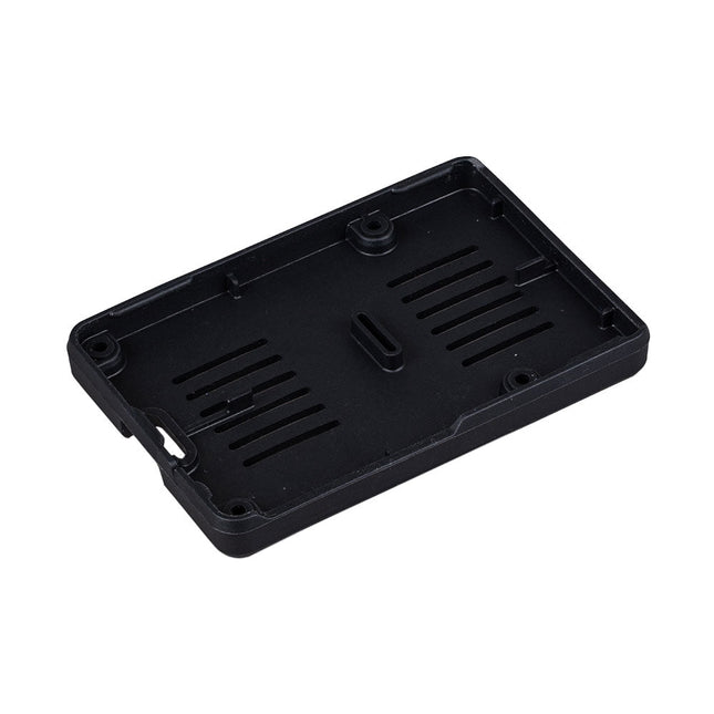
De Raspberry Pi Bumper is een opklikbare siliconen hoes die de onderkant en randen van de Raspberry Pi 5 beschermt.
Kenmerken
Flexibele siliconenrubberen bumper uit één stuk
Maakt gemakkelijke toegang tot de aan/uit-knop mogelijk
Bevestigingsgaten blijven toegankelijk onder de bumper
Downloads
Datasheet
Creëer bliksem met een aanraking van je vingers of een handgeklap
De Plasma Magic Ball is een geavanceerde technologische gadget en een opvallend kunstwerk. In de glazen bol creëert een speciaal gasmengsel betoverende lichteffecten wanneer het wordt geactiveerd door hoogfrequente stroom – alsof je een storm in je handen houdt.
Perfect voor gebruik thuis, op kantoor, op school, in hotels of in bars. Het is een uniek decoratief element dat nieuwsgierigheid opwekt. Op zoek naar een leuk en bijzonder cadeau? De Plasma Magic Ball is een geweldige keuze voor vrienden en familie.
Ondanks de verbluffende effecten verbruikt de Plasma Magic Ball zeer weinig elektriciteit. Het glas zelf is gemaakt van speciaal gehard, zeer sterk materiaal en is bestand tegen temperaturen tot 522°C.
Specificaties
Materiaal
Kunststof
Diameter bal
15 cm
Ingangsspanning
220 V
Uitgangsspanning
12 V
Vermogen
15 W
Afmetingen
25 x 15,5 x 15,5 cm
35 Touch Develop & MicroPython Projects
The BBC micro:bit is a credit sized computer based on a highly popular and high performance ARM processor. The device is designed by a group of 29 partners for use in computer education in the UK and will be given free of charge to every secondary school student in the UK.
The device is based on the Cortex-M0 processor and it measures 4 x 5 cm. It includes several important sensors and modules such as an accelerometer, magnetometer, 25 LEDs, 2 programmable push-button switches, Bluetooth connectivity, micro USB socket, 5 ring type connectors, and a 23-pin edge connector. The device can be powered from its micro USB port by connecting it to a PC, or two external AAA type batteries can be used.
This book is about the use of the BBC micro:bit computer in practical projects. The BBC micro:bit computer can be programmed using several different programming languages, such as Microsoft Block Editor, Microsoft Touch Develop, MicroPython, and JavaScript.
The book makes a brief introduction to the Touch Develop programming language and the MicroPython programming language. It then gives 35 example working and tested projects using these language. Readers who learn to program in Touch Develop and MicroPython should find it very easy to program using the Block Editor or any other languages.
The following are given for each project:
Title of the project
Description of the project
Aim of the project
Touch Develop and MicroPython program listings
Complete program listings are given for each project. In addition, working principles of the projects are described briefly in each section. Readers are encouraged to go through the projects in the order given in the book.
NRF24L01 is a universal ISM band monolithic transceiver chip works in the 2.4-2.5 GHz. Features Wireless transceiver including: Frequency generator, enhanced type, SchockBurstTM, mode controller, power amplifier, crystal amplifier, modulator, demodulator The output power channel selection and protocol settings can be set extremely low current consumption, through the SPI interface As the transmit mode, the transmit power is 6 dBm, the current is 9.0 mA, the accepted mode current is 12.3 mA, the current consumption of the power-down mode and standby mode are lower Built-in 2.4 GHz antenna, supports up to six channels of data reception Size: 15 x 29 mm (including antenna)
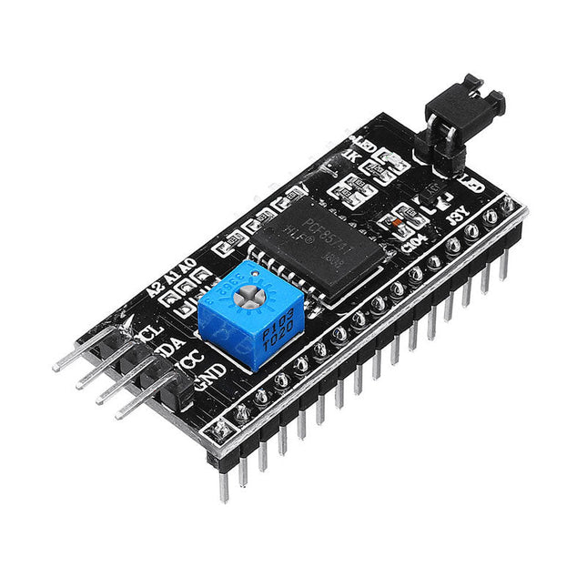
This is another great IIC/I²C/TWI/SPI Serial Interface. As the pin resources of controller is limited, your project may be not able to use normal LCD shield after connected with a certain quantity of sensors or SD card. However, with this I²C interface module, you will be able to realize data display via only 2 wires. If you already has I²C devices in your project, this LCD module actually cost no more resources at all. It is fantastic for based project. I²C Address: 0X20~0X27 (the original address is 0X20,you can change it yourself) The backlight and contrast is adjusted by potentiometer Comes with 2 IIC interface, which can be connected by Dupont Line or IIC dedicated cable I²C Address: 0x27 (I²C Address: 0X20~0X27 (the original address is 0X27,you can change it yourself) Specifications Compatible for 1602 LCD Supply voltage: 5 V Weight: 5 g Size: 5.5 x 2.3 x 1.4 cm
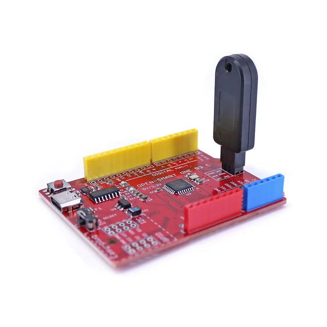
Deze programmeur is speciaal ontworpen voor het branden van bootloaders (zonder computer) op Arduino-compatibele ATmega328P/ATmega328PB-ontwikkelborden.
Sluit de programmeur eenvoudigweg aan op de ICSP-interface om de bootloader opnieuw te branden. Het is ook compatibel met nieuwe chips, op voorwaarde dat de IC functioneel is.
Opmerking: Als u een bootloader brandt, worden alle eerdere chipgegevens gewist.
Kenmerken
Werkspanning: 3,1-5,3 V
Werkstroom: 10 mA
Compatibel met op Arduino Uno R3 gebaseerde borden (ATmega328P of ATmega328PB)
Afmetingen: 39,6 x 15,5 x 7,8 mm
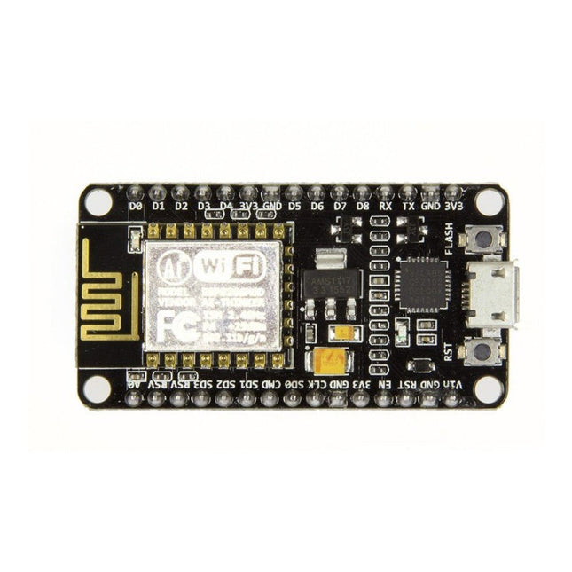
Note: NodeMCU is the name of both a firmware and a boardNodeMCU is an open source IoT platform, whose firmware runs on Espressif's SoC Wi-Fi ESP8266, based on the ESP8266 nonOS SDK. Its hardware is based on the ESP-12 module. The scripting language is Lua which allows to use many open source projects like lua-cjson and spiffs.Features
Wi-Fi Module – ESP-12E module similar to ESP-12 module but with 6 extra GPIOs.
USB – micro USB port for power, programming and debugging
Headers – 2x 2.54 mm 15-pin header with access to GPIOs, SPI, UART, ADC, and power pins
Reset & Flash buttons
Power: 5V via micro USB port
Dimensions: 49 x 24.5 x 13 mm
Features
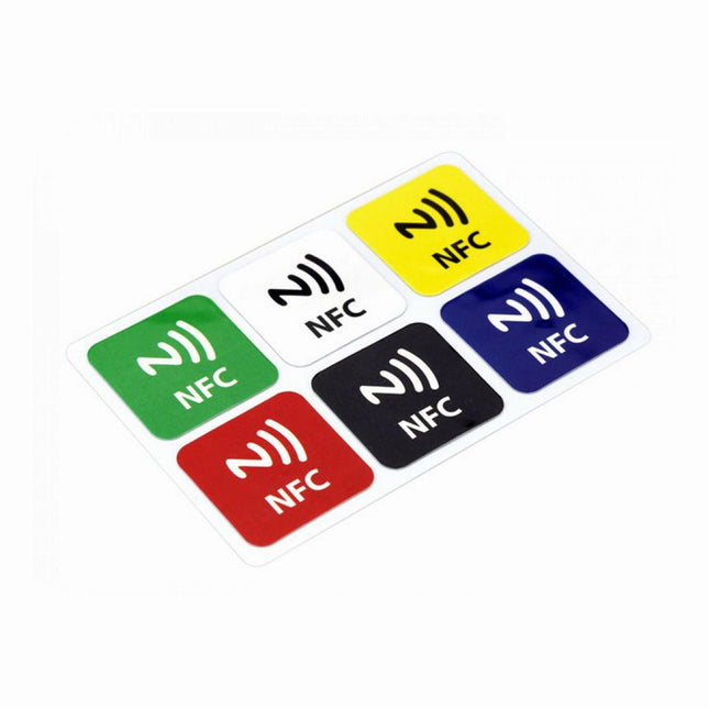
NFC chip material: PET + Etching antenna
Chip: NTAG216 (compatible with all NFC phones)
Frequency: 13.56 MHz (High Frequency)
Reading time: 1-2 ms
Storage capacity: 888 bytes
Read and write times: > 100,000 times
Reading distance: 0-5 mm
Data retention: > 10 years
NFC chip size: Diameter 30 mm
Non-contact, no friction, the failure rate is small, low maintenance costs
Read rate, verification speed, which can effectively save time and improve efficiency
Waterproof, dustproof, anti-vibration
No power comes with an antenna, embedded encryption control logic, and communication logic circuit
Included
1x NFC Stickers (6-color kit)
Een gemakkelijke manier om onderdelen tijdens het solderen aan de onderkant van een PCB vast te houden
PartLift houdt onderdelen met doorlopende gaten op hun plaats zodat u uw handen vrij heeft terwijl u de benen soldeert. Een eenvoudig maar nuttig hulpmiddel voor bij uw Stickvise. De basispad is van antislip siliconenschuim, de behuizing van het gereedschap is van ABS, wat zorgt voor een zeer lichte veerspanning om uw onderdeel op zijn plaats te houden. De punt van het gereedschap is gemaakt van siliconen die bestand zijn tegen hoge temperaturen en bestand zijn tegen soldeertemperaturen zonder beschadigd te raken.
Kenmerken
PartLift houdt doorlopende onderdelen op hun plaats tijdens het solderen
Gebruik met een Stickvise of een andere PCB-houder met laag profiel
De punt is van siliconen die bestand is tegen soldeertemperaturen
Het basiskussen is gemaakt van antislip siliconenschuim
Specificaties
Materiaal
Siliconen
Afmetingen
109 x 40 x 40 mm
Gewicht
59 g
Raspberry Pi 5 provides two four-lane MIPI connectors, each of which can support either a camera or a display. These connectors use the same 22-way, 0.5 mm-pitch “mini” FPC format as the Compute Module Development Kit, and require adapter cables to connect to the 15-way, 1 mm-pitch “standard” format connectors on current Raspbery Pi camera and display products.These mini-to-standard adapter cables for cameras and displays (note that a camera cable should not be used with a display, and vice versa) are available in 200 mm, 300 mm and 500 mm lengths.
Specificaties
Dubbele ARM Cortex-M0+ @ 133 MHz
264 kB on-chip SRAM in zes onafhankelijke banken
Ondersteuning tot 16 MB off-chip Flash memory via speciale QSPI bus
DMA-controller
Volledig aangesloten AHB crossbar
Interpolator en integer divider peripherals
On-chip programmeerbare LDO om spanning voor de core te genereren
2x on-chip PLL's om USB en core kloksignalen te genereren
30x GPIO pins, waarvan er 4 als analoge ingangen kunnen worden gebruikt
Randapparatuur
2x UARTs
2x SPI controllers
2x I²C controllers
16x PWM kanalen
USB 1.1 controller en PHY, met host en device support
8x PIO state machines
Wat je krijgt
10x RP2040 ICs
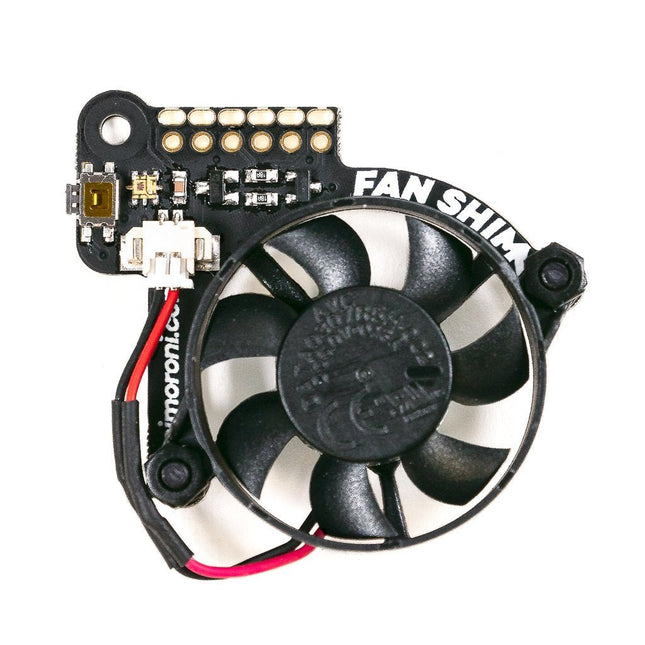
When Raspberry Pi 4's system on chip (SoC) achieves a certain temperature, it lowers its operating speed to protect itself from harm. As a result, you don't get maximum performance from the single board computer. Fan SHIM is an affordable accessory that effectively eliminates thermal throttling and boosts the performance of RPi 4. It's quite easy to attach the fan SHIM to Raspberry pi: fan SHIM uses a friction-fit header, so it just slips onto your Pi's pins and it's ready to go, no soldering required! The fan can be controlled in software, so you can adjust it to your needs, for example, toggle it on when the CPU reaches a certain temperature etc. You can also program the LED as a visual indicator of the fan status. The tactile switch can also be programmed, so you can use it to toggle the fan on or off, or to switch between temperature-triggered or manual mode. Features 30 mm 5 V DC fan 4,200 RPM 0.05 m³/min air flow 18.6 dB acoustic noise (whisper-quiet) Friction-fit header No soldering required RGB LED (APA102) Tactile switch Basic assembly required Compatible with Raspberry Pi 4 (and 3B+, 3A+)
Python library and daemon Pinout Scope of delivery Fan SHIM PCB 30 mm 5 V DC fan with JST connector M2.5 nuts and bolts Assembly The assembly is really simple and almost takes no time With the component side of the PCB facing upwards, push the two M2.5 bolts through the holes from below, then screw on the first pair of nuts to secure them and act as spacers. Push the fan's mounting holes down onto the bolts, with the cable side of the fan downwards (as pictured) and the text on the fan upwards. Attach with another two nuts. Push the fan's JST connector into the socket on Fan SHIM. Software With the help of Python library you can control the fan (on/off), RGB LED, and switch. You'll also find a number of examples that demonstrate each feature, as well as a script to install a daemon (a computer program that runs as a background process) that runs the fan in automatic mode, triggering it on or off when the CPU reaches a threshold temperature, with a manual override via the tactile switch.
Fully updated for Raspberry Pi 5
Raspberry Pi is a small, clever, British-built computer that's packed with potential. Made using a desktop-class, energy-efficient processor, Raspberry Pi is designed to help you learn coding, discover how computers work, and build your own amazing things. This book was written to show you just how easy it is to get started.
Learn how to:
Set up your Raspberry Pi, install its operating system, and start using this fully functional computer.
Start coding projects, with step-by-step guides using the Scratch 3, Python, and MicroPython programming languages.
Experiment with connecting electronic components, and have fun creating amazing projects.
New in the 5th edition:
Updated for the latest Raspberry Pi computers: Raspberry Pi 5 and Raspberry Pi Zero 2 W.
Covers the latest Raspberry Pi OS.
Includes a new chapter on the Raspberry Pi Pico.
Downloads
GitHub
Een verbeterde kakenset die bestand is tegen direct contact met een soldeerbout
Stickvise PTFE-klemkaken voor hoge temperaturen zijn bestand tegen onbedoeld contact met een soldeerbout en smelten niet. Dit is een geweldige upgrade voor je Stickvise.
Kenmerken
Gemaakt van PTFE met extreem hoog smeltpunt
Bestand tegen incidenteel contact met een soldeerbout
Dit zijn alleen de kaakplaten, er zit geen Stickvise bij
Specificaties
Materiaal
Aluminium
Afmetingen
73 x 53 x 3 mm
Gewicht
21 g
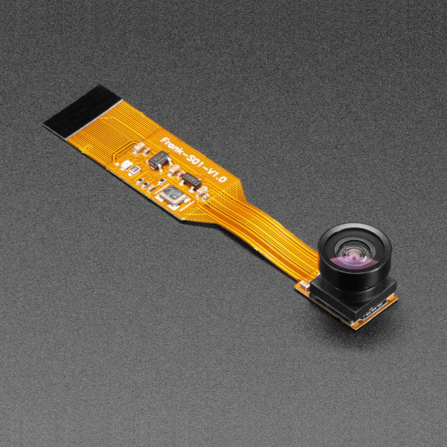
Spookt het in je huis? Of, beter gezegd, ben je ervan overtuigd dat het spookt in je huis, maar heb je het nooit kunnen bewijzen omdat je nooit een camera hebt gehad die geïntegreerd is met je Raspberry Pi Zero, maar toch klein genoeg is om de spoken niet op te merken?Gelukkig is de spionagecamera voor Raspberry Pi Zero kleiner dan een duimnagel met een resolutie die hoog genoeg is om mensen, geesten, of wat het ook is dat je zoekt, te zien. Hij is ongeveer zo groot als een mobiele telefooncamera - de module is slechts 8,6 x 8,6 mm - met slechts een 2' kabel, zodat je een extra compacte en geniepige kleine spioncamera kunt maken. Hij heeft een openingshoek van 160 graden voor een zeer breed/vervormd fisheye effect dat geweldig is voor beveiligingssystemen of om een groot deel van de woonkamer of de weg te bekijken..Net als het Raspberry Pi cameraboard wordt het op je Raspberry Pi Zero v1.3 of Zero W aangesloten via de kleine aansluiting op de rand van het board dicht bij de 'PWR in' aansluiting. Deze interface maakt gebruik van de speciale CSI interface, die speciaal is ontworpen voor interfacing met camera's. De CSI bus kan extreem hoge datasnelheden aan, en transporteert uitsluitend pixelgegevens.De camera is verbonden met de BCM2835 processor op de RPi via de CSI bus, een verbinding met hogere bandbreedte die pixelgegevens van de camera terugvoert naar de processor. Deze bus loopt via de lintkabel waarmee het cameraboard aan de Pi is bevestigd. De lintkabels zijn compatibel met zowel de RPi Zero v1.3 als de RPi Zero W.De sensor zelf heeft een native resolutie van 5 megapixels en heeft een lens met vaste focus aan boord. Hij heeft vergelijkbare specificaties als de originele RPi camera, maar is niet zo high-res als de nieuwe RPi camera v2!Specificaties
Afmetingen cameramodule: 8,6 x 8,6 mm
Diameter lens: 10 mm
Totale lengte: 60 mm
Openingshoek lens: 160 graden
Gewicht: 1,9 g
De Raspberry Pi Pico 2 H (met headers) is een nieuw microcontrollerbord van de Raspberry Pi Foundation, gebaseerd op de RP2350. Het beschikt over een hogere kloksnelheid, het dubbele van de on-chip SRAM, het dubbele van het ingebouwde flashgeheugen, krachtigere Arm-cores, optionele RISC-V-cores, nieuwe beveiligingsfuncties en verbeterde interfacemogelijkheden. De Raspberry Pi Pico 2 H biedt een aanzienlijke verbetering in prestaties en functies, terwijl de hardware- en softwarecompatibiliteit met eerdere leden van de Raspberry Pi Pico-serie behouden blijft.
De RP2350 biedt een uitgebreide beveiligingsarchitectuur gebouwd rond Arm TrustZone voor Cortex-M. Het bevat ondertekend opstarten, 8 KB antifuse OTP voor sleutelopslag, SHA-256-versnelling, een hardware TRNG en snelle glitch-detectoren.
Dankzij de unieke dual-core en dual-architectuurmogelijkheden van de RP2350 kunnen gebruikers kiezen tussen een paar industriestandaard Arm Cortex-M33-kernen en een paar open-hardware Hazard3 RISC-V-kernen. Programmeerbaar in C/C++ en Python, en ondersteund door gedetailleerde documentatie, is de Raspberry Pi Pico 2 het ideale microcontrollerbord voor zowel liefhebbers als professionele ontwikkelaars.
Specificaties
CPU
Dual Arm Cortex-M33 of dubbele RISC-V Hazard3-processors @ 150 MHz
Geheugen
520 KB SRAM op de chip; 4 MB ingebouwde QSPI-flitser
Interfaces
26 multifunctionele GPIO-pinnen, waaronder 4 die kunnen worden gebruikt voor AD
Randapparatuur
2x UART
2x SPI-controllers
2x I²C-controllers
24x PWM-kanalen
1x USB 1.1-controller en PHY, met host- en apparaatondersteuning
12x PIO-statusmachines
Ingangsvermogen
1,8-5,5 V DC
Afmetingen
21 x 51 mm
Downloads
Datasheet (Pico 2)
Datasheet (RP2350)
Universele pen voor gebruik op nagenoeg alle oppervlakken Geschikt voor OHP Ook geschikt om op CD's en DVD's te schrijven Excellente veegvastheid en waterbestendigheid op nagenoeg alle oppervlakken Droog na luttele seconden, daarom ook ideaal voor linkshandigen Permanente, nagenoeg geurloze inkt Lichtbestendige kleuren: zwart, bruin Zwart is weersbestendig Opstelbare STAEDTLER box PP lichaam en dop voor een lange levensduur DRY SAFE - kan dagenlang open liggen zonder uitdrogen (Test ISO 554) Airplane safe - automatische aanpassing van de druk voorkomt het lekken van de pen aan boord van een vliegtuig Zonder xyleen en tolueen Schitterende kleuren Ljnbreedte S - Superfijn (ca. 0.4 mm) Navulbaar
Raspberry Pi 5 provides two four-lane MIPI connectors, each of which can support either a camera or a display. These connectors use the same 22-way, 0.5 mm-pitch “mini” FPC format as the Compute Module Development Kit, and require adapter cables to connect to the 15-way, 1 mm-pitch “standard” format connectors on current Raspbery Pi camera and display products.These mini-to-standard adapter cables for cameras and displays (note that a camera cable should not be used with a display, and vice versa) are available in 200 mm, 300 mm and 500 mm lengths.
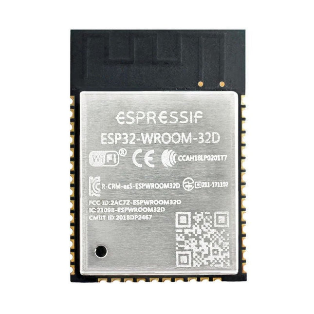
The ESP32-WROOM-32, measuring 25.2 x 18 mm only, contains the ESP32 SoC, flash memory, precision discrete components, and PCB antenna to provide outstanding RF performance in space-constrained applications.
ESP32-WROOM-32 is a powerful, generic Wi-Fi + BT + BLE MCU module that targets a wide variety of applications, ranging from low-power sensor networks to the most demanding tasks, such as voice encoding, music streaming and MP3 decoding.
At the core of this module is the ESP32-D0WDQ6 chip. The chip embedded is designed to be scalable and adaptive. There are two CPU cores that can be individually controlled, and the clock frequency is adjustable from 80 MHz to 240 MHz. The user may also power off the CPU and make use of the low-power co-processor to monitor the peripherals for changes or crossing of thresholds constantly. ESP32 integrates a rich set of peripherals, ranging from capacitive touch sensors, Hall sensors, SD card interface, Ethernet, high-speed SPI, UART, I²S and I²C.
The integration of Bluetooth, Bluetooth LE and Wi-Fi ensures that a wide range of applications can be targeted and that the module is future proof. Using Wi-Fi allows a vast physical range and direct connection to the internet through a Wi-Fi router while using Bluetooth allows the user to conveniently connect to the phone or broadcast low energy beacons for its detection.
The sleep current of the ESP32 chip is less than 5 µA, making it suitable for battery powered and wearable electronics applications. ESP32 supports a data rate of up to 150 Mbps, and 20.5 dBm output power at the antenna to ensure the broadest physical range. As such the chip does offer industry-leading specifications and the best performance for electronic integration, range, power consumption, and connectivity.
Downloads
Datasheet
Inside the RP2040 is a 'permanent ROM' USB UF2 bootloader. What that means is when you want to program new firmware, you can hold down the BOOTSEL button while plugging it into USB (or pulling down the RUN/Reset pin to ground) and it will appear as a USB disk drive you can drag the firmware onto. Folks who have been using Adafruit products will find this very familiar – Adafruit uses the technique on all thier native-USB boards. Just note you don't double-click reset, instead hold down BOOTSEL during boot to enter the bootloader!The RP2040 is a powerful chip, which has the clock speed of our M4 (SAMD51), and two cores that are equivalent to our M0 (SAMD21). Since it is an M0 chip, it does not have a floating point unit, or DSP hardware support – so if you're doing something with heavy floating-point math, it will be done in software and thus not as fast as an M4. For many other computational tasks, you'll get close-to-M4 speeds!For peripherals, there are two I²C controllers, two SPI controllers, and two UARTs that are multiplexed across the GPIO – check the pinout for what pins can be set to which. There are 16 PWM channels, each pin has a channel it can be set to (ditto on the pinout).Technical Specifications
Measures 2.0 x 0.9 x 0.28' (50.8 x 22.8 x 7 mm) without headers soldered in
Light as a (large?) feather – 5 grams
RP2040 32-bit Cortex M0+ dual core running at ~125 MHz @ 3.3 V logic and power
264 KB RAM
8 MB SPI FLASH chip for storing files and CircuitPython/MicroPython code storage. No EEPROM
Tons of GPIO! 21 x GPIO pins with following capabilities:
Four 12 bit ADCs (one more than Pico)
Two I²C, Two SPI and two UART peripherals, one is labeled for the 'main' interface in standard Feather locations
16 x PWM outputs - for servos, LEDs, etc
The 8 digital 'non-ADC/non-peripheral' GPIO are consecutive for maximum PIO compatibility
Built in 200 mA+ lipoly charger with charging status indicator LED
Pin #13 red LED for general purpose blinking
RGB NeoPixel for full color indication.
On-board STEMMA QT connector that lets you quickly connect any Qwiic, STEMMA QT or Grove I²C devices with no soldering!
Both Reset button and Bootloader select button for quick restarts (no unplugging-replugging to relaunch code)
3.3 V Power/enable pin
Optional SWD debug port can be soldered in for debug access
4 mounting holes
24 MHz crystal for perfect timing.
3.3 V regulator with 500mA peak current output
USB Type C connector lets you access built-in ROM USB bootloader and serial port debugging
RP2040 Chip Features
Dual ARM Cortex-M0+ @ 133 MHz
264 kB on-chip SRAM in six independent banks
Support for up to 16 MB of off-chip Flash memory via dedicated QSPI bus
DMA controller
Fully-connected AHB crossbar
Interpolator and integer divider peripherals
On-chip programmable LDO to generate core voltage
2 on-chip PLLs to generate USB and core clocks
30 GPIO pins, 4 of which can be used as analog inputs
Peripherals
2 UARTs
2 SPI controllers
2 I²C controllers
16 PWM channels
USB 1.1 controller and PHY, with host and device support
8 PIO state machines
Comes fully assembled and tested, with the UF2 USB bootloader. Adafruit also tosses in some header, so you can solder it in and plug it into a solderless breadboard.
Raspberry Pi Pico Wireless Pack attaches to the back of your Pico and uses an ESP32 chip to let your Pico connect to 2.4 GHz wireless networks and transfer data. There's a microSD card slot for if you want to store lots of data locally as well as a RGB LED (for status updates) and a button (useful for things like enabling/disabling Wi-Fi).Great for quickly adapting an existing Pico project to have wireless functionality, Raspberry Pi Pico Wireless Pack would come in handy for sending sensor data into home automation systems or dashboards, for hosting a web page from a matchbox or for letting your Pico interact with online APIs.Features
ESP32-WROOM-32E module for wireless connectivity (connected via SPI) (datasheet)
1x tactile button
RGB LED
Micro-SD card slot
Pre-soldered female headers for attaching your Raspberry Pi Pico
Fully assembled
No soldering required (as long as your Pico has header pins attached)
Compatible with Raspberry Pi Pico
Dimensions: approx 53 x 25 x 11 mm (L x W x H, including headers and components)
C++ and MicroPython libraries
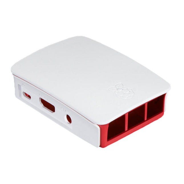
High-quality ABS construction Removable side panels and lid for easy access to GPIO, camera and display connectors Light pipes for power and activity LEDs Extraordinarily handsome Colour: white/red