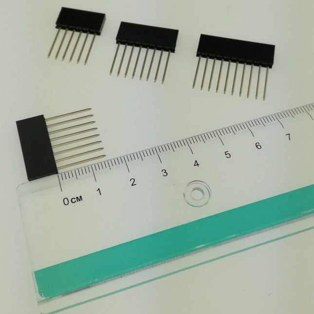
Features Build in USB to Serial interface Build-in PCB antenna Powered by Pineseed BL602 SoC using Pinenut model: 12S stamp 2 MB Flash USB-C connection Suitable to breadboard BIY project On board three color LEDs output Dimensions: 25.4 x 44.0 mm Note: USB cable is not included.
De M12-mountlens (12 MP, 8 mm) is ideaal voor gebruik met de Raspberry Pi HQ Cameramodule en levert scherpe, gedetailleerde beelden voor uiteenlopende toepassingen.
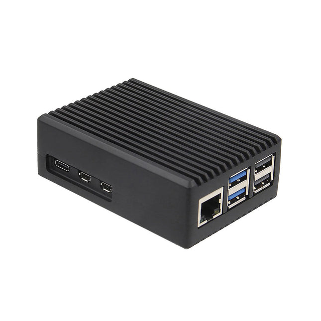
Deze robuuste, passieve aluminium koelbehuizing is speciaal gemaakt voor de Raspberry Pi 5 en biedt een strak ontwerp dat zowel duurzaamheid als effectieve warmteafvoer garandeert. De behuizing is exclusief compatibel met de Raspberry Pi 5 en biedt een passieve koeloplossing, waardoor er geen ventilator meer nodig is en de warmte toch efficiënt wordt beheerd.
Kenmerken
Hoogwaardige aluminium constructie: Deze behuizing is gemaakt van hoogwaardig aluminium en is gebouwd om lang mee te gaan en bestand te zijn tegen regelmatig gebruik.
Geoptimaliseerde warmteafvoer: Het passieve koelingsontwerp maakt gebruik van de aluminium structuur om uw Raspberry Pi 5 koel te houden zonder dat er een ventilator nodig is.
Volledige poorttoegankelijkheid: Elke poort op de Raspberry Pi 5 is gemakkelijk toegankelijk, van de microSD-kaartsleuf tot USB-, micro-HDMI- en GPIO-poorten.
GPIO-kabelondersteuning: Een gereserveerde interface voor de GPIO-kabel zorgt ervoor dat u deze belangrijke functie kunt blijven gebruiken zonder dat u de behuizing hoeft te verwijderen.
Handige aan/uit-schakelaar: De case heeft een geïntegreerde aan/uit-schakelaar waarmee u uw apparaat aan en uit kunt zetten.
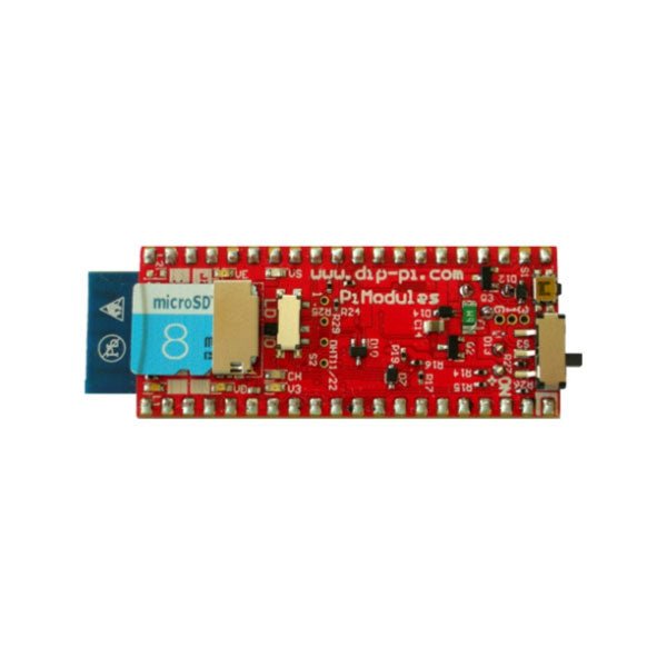
The DiP-Pi PIoT is an Advanced Powered, WiFi connectivity System with sensors embedded interfaces that cover most of possible needs for IoT application based on Raspberry Pi Pico. It can supply the system with up to 1.5 A @ 4.8 V delivered from 6-18 VDC on various powering schemes like Cars, Industrial plant etc., additionally to original micro-USB of the Raspberry Pi Pico. It supports LiPo or Li-Ion Battery with Automatic Charger as also automatic switching from cable powering to battery powering or reverse (UPS functionality) when cable powering lost. Extended Powering Source (EPR) is protected with PPTC Resettable fuse, Reverse Polarity, as also ESD.The DiP-Pi PIoT contains Raspberry Pi Pico embedded RESET button as also ON/OFF Slide Switch that is acting on all powering sources (USB, EPR or Battery). User can monitor (via Raspberry Pi Pico A/D pins) battery level and EPR Level with PICO’s A/D converters. Both A/D inputs are bridged with 0402 resistors (0 OHM) therefore if for any reason user needs to use those Pico pins for their own application can be easy removed. The charger is automatically charging connected battery (if used) but in addition user can switch charger ON/OFF if their application needs it.DiP-Pi PIoT can be used for cable powered IoT systems, but also for pure Battery Powered System with ON/OFF. Each powering source status is indicated by separate informative LEDs (VBUS, VSYS, VEPR, CHGR, V3V3).User can use any capacity of LiPo or Li-Ion type; however, must take care to use PCB protected batteries with max discharge current allowed of 2 A. The embedded battery charger is set to charge battery with 240 mA current. This current is set by resistor so if user need more/less can himself to change it. The DiP-Pi PIoT is also equipped with WiFi ESP8266 Clone module with embedded antenna. This feature open a wide range of IoT applications based on it.In Addition to all above features DiP-Pi PIoT is equipped with embedded 1-wire, DHT11/22 sensors, and micro–SD Card interfaces. Combination of the extended powering, battery, and sensors interfaces make the DiP-Pi PIoT ideal for IoT applications like data logger, plants monitoring, refrigerators monitoring etc.DiP-Pi PIoT is supported with plenty of ready to use examples written in Micro Python or C/C++.SpecificationsGeneral
Dimensions 21 x 51 mm
Raspberry Pi Pico pinout compatible
Independent Informative LEDs (VBUS, VSYS, VEPR, CHGR, V3V3)
Raspberry Pi Pico RESET Button
ON/OFF Slide Switch acting on all powering sources (USB, EPR, Battery)
External Powering 6-18 VDC (Cars, Industrial Applications etc.)
External Power (6-18 VDC) Level Monitoring
Battery Level Monitoring
Inverse Polarity Protection
PPTC Fuse Protection
ESD Protection
Automatic Battery Charger (for PCB protected LiPo, Li-Ion – 2 A Max) Automatic/User Control
Automatic Switch from Cable Powering to Battery Powering and reverse (UPS Functionality)
Various powering schemes can be used at the same time with USB Powering, External Powering and Battery Powering
1.5 A @ 4.8 V Buck Converter on EPR
Embedded 3.3 V @ 600 mA LDO
ESP8266 Clone WiFi Connectivity
ESP8266 Firmware Upload Switch
Embedded 1-wire Interface
Embedded DHT-11/22 Interface
Powering Options
Raspberry Pi Pico micro-USB (via VBUS)
External Powering 6-18 V (via dedicated Socket – 3.4/1.3 mm)
External Battery
Supported Battery Types
LiPo with protection PCB max current 2A
Li-Ion with protection PCB max current 2A
Embedded Peripherals and Interfaces
Embedded 1-wire interface
Embedded DHT-11/22 Interface
Micro SD Card Socket
Programmer Interface
Standard Raspberry Pi Pico C/C++
Standard Raspberry Pi Pico Micro Python
Case CompatibilityDiP-Pi Plexi-Cut CaseSystem Monitoring
Battery Level via Raspberry Pi Pico ADC0 (GP26)
EPR Level via Raspberry Pi Pico ADC1 (GP27)
Informative LEDs
VB (VUSB)
VS (VSYS)
VE (VEPR)
CH (VCHR)
V3 (V3V3)
System Protection
Direct Raspberry Pi Pico Hardware Reset Button
ESD Protection on EPR
Reverse Polarity Protection on EPR
PPTC 500 mA @ 18 V fuse on EPR
EPR/LDO Over Temperature protection
EPR/LDO Over Current protection
System Design
Designed and Simulated with PDA Analyzer with one of the most advanced CAD/CAM Tools – Altium Designer
Industrial Originated
PCB Construction
2 ozcopper PCB manufactured for proper high current supply and cooling
6 mils track/6 mils gap technology 2 layers PCB
PCB Surface Finishing – Immersion Gold
Multi-layer Copper Thermal Pipes for increased System Thermal Response and better passive cooling
Downloads
Datasheet
Manual
Features Dual-Core 64-bit RISC-V RV64IMAFDC (RV64GC) CPU / 400Mhz(Normal) Dual Independent Double Precision FPU 8MiB 64bit width On-Chip SRAM Neural Network Processor(KPU) / 0.8Tops Field-Programmable IO Array (FPIOA) AES, SHA256 Accelerator Direct Memory Access Controller (DMAC) Micropython Support Firmware encryption support On-board Hardware: Flash: 16M Camera :OV7740 2x Buttons Status Indicator LED External storage: TF card/Micro SD Interface: HY2.0/compatible GROVE Applications Face recognition/detection Object detection/classification Obtain the size and coordinates of the target in real-time Obtain the type of detected target in real-time Shape recognition Video recorder Included 1x UNIT-V(include 20cm 4P cable and USB-C cable)
With a 6x20 grid of 2.54 mm spaced holes for easy soldering and labelled Pico pins so you know what's what, Pico Proto is perfect for when you're happy with your breadboard project and want to give it a secure, smart and compact long-term home. Pico Proto doesn't come with any headers attached, so you will need to either solder it directly to your Pico's male header pins (for a permanent, but super slim sandwich) or solder it to some female header. Features 40 2.54 mm spaced holes for attaching to your Pico. 120 2.54 mm spaced holes (6x20 grid) for attaching other things Compatible with Raspberry Pi Pico. Dimensions: approx 51 x 25 x 1 mm (L x W x H)
Raspberry Pi 5 provides two four-lane MIPI connectors, each of which can support either a camera or a display. These connectors use the same 22-way, 0.5 mm-pitch “mini” FPC format as the Compute Module Development Kit, and require adapter cables to connect to the 15-way, 1 mm-pitch “standard” format connectors on current Raspbery Pi camera and display products.These mini-to-standard adapter cables for cameras and displays (note that a camera cable should not be used with a display, and vice versa) are available in 200 mm, 300 mm and 500 mm lengths.
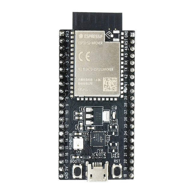
ESP32-S2-Saola-1R is a small-sized ESP32-S2 based development board. Most of the I/O pins are broken out to the pin headers on both sides for easy interfacing. Developers can either connect peripherals with jumper wires or mount ESP32-S2-Saola-1R on a breadboard.ESP32-S2-Saola-1R is equipped with the ESP32-S2-WROVER module, a powerful, generic Wi-Fi MCU module that has a rich set of peripherals. It is an ideal choice for a wide variety of application scenarios relating to Internet of Things (IoT), wearable electronics and smart home. The board a PCB antenna and features a 4 MB external SPI flash and an additional 2 MB SPI Pseudo static RAM (PSRAM).FeaturesMCU
ESP32-S2 embedded, Xtensa® single-core 32-bit LX7 microprocessor, up to 240 MHz
128 KB ROM
320 KB SRAM
16 KB SRAM in RTC
WiFi
802.11 b/g/n
Bit rate: 802.11n up to 150 Mbps
A-MPDU and A-MSDU aggregation
0.4 µs guard interval support
Center frequency range of operating channel: 2412 ~ 2484 MHz
Hardware
Interfaces: GPIO, SPI, LCD, UART, I²C, I²S, Camera interface, IR, pulse counter, LED PWM, TWAI (compatible with ISO 11898-1), USB OTG 1.1, ADC, DAC, touch sensor, temperature sensor
40 MHz crystal oscillator
4 MB SPI flash
Operating voltage/Power supply: 3.0 ~ 3.6 V
Operating temperature range: –40 ~ 85 °C
Dimensions: 18 × 31 × 3.3 mm
Applications
Generic Low-power IoT Sensor Hub
Generic Low-power IoT Data Loggers
Cameras for Video Streaming
Over-the-top (OTT) Devices
USB Devices
Speech Recognition
Image Recognition
Mesh Network
Home Automation
Smart Home Control Panel
Smart Building
Industrial Automation
Smart Agriculture
Audio Applications
Health Care Applications
Wi-Fi-enabled Toys
Wearable Electronics
Retail & Catering Applications
Smart POS Machines
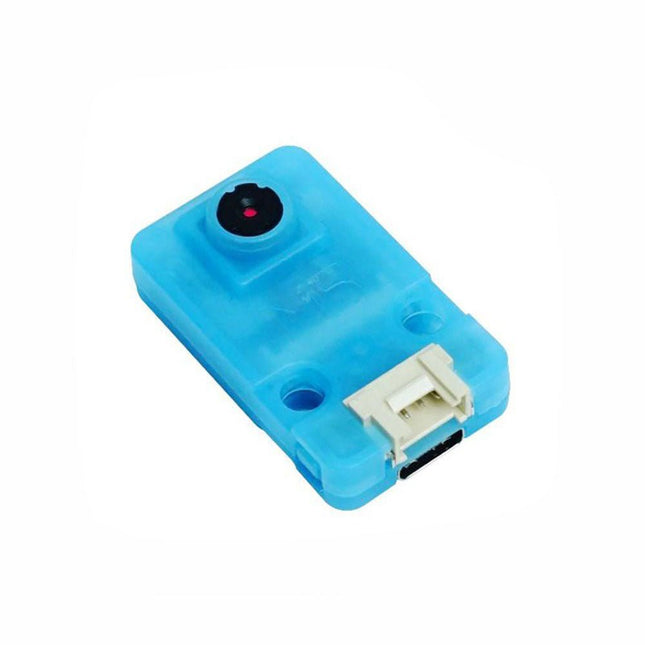
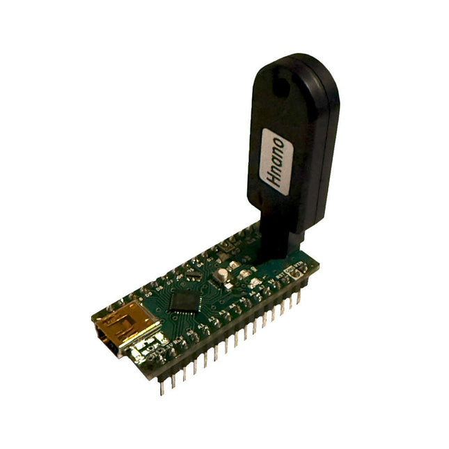
Deze programmeur is speciaal ontworpen voor het branden van bootloaders (zonder computer) op Arduino-compatibele ATmega328-ontwikkelborden.
Sluit de programmeur eenvoudigweg aan op de ICSP-interface om de bootloader opnieuw te branden. Het is ook compatibel met nieuwe chips, op voorwaarde dat de IC functioneel is.
Opmerking: Als u een bootloader brandt, worden alle eerdere chipgegevens gewist.
Kenmerken
Werkspanning: 3,1-5,3 V
Werkstroom: 10 mA
Compatibel met op Arduino Nano gebaseerde borden (ATmega328)
Afmetingen: 39,6 x 15,5 x 7,8 mm
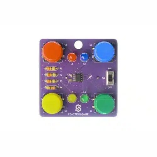
If you are looking for a simple way to learn soldering, or just want to make a small gadget that you can carry, this set is a great opportunity. Reaction game is an educational kit which teaches you how to solder, and in the end, you get to have your own small game. The goal of the game is to press the button next to the LED as soon as it turns on. With every correct answer, the game gets a bit harder – the time you have to press the button shortens. How many correct answers can you get?
It’s based on ATtiny404 microcontroller, programmed in Arduino. At its back, you’ll find CR2032 battery which makes the kit portable. There’s keychain holder as well. Soldering process is easy enough based on the mark on the PCB.
Included
1x PCB
1x ATtiny404 microcontroller
4x LEDs
4x Pushbuttons
1x Switch
4x Resistors (330 ohm)
1x CR2032 battery holder
1x Battery CR2032
1x Keychain holder
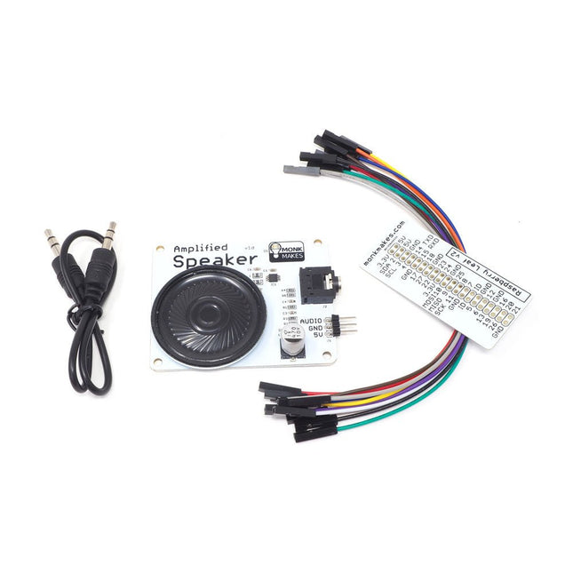
The Speaker Kit for Raspberry Pi is a small amplified speaker designed for the Raspberry Pi. Included MonkMakes Amplified Speaker Set of 10 female to female header wires Short stereo audio lead Raspberry Leaf GPIO template Downloads Instructions Datasheet
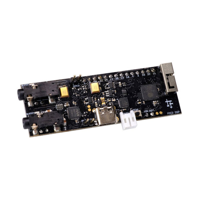
PÚCA DSP is an open-source, Arduino-compatible ESP32 development board for audio and digital signal processing (DSP) applications with expansive audio-processing features. It provides audio inputs, audio outputs, a low-noise microphone array, an integrated test-speaker option, additional memory, battery-charge management, and ESD protection all on a small, breadboard-friendly PCB.
Synthesizers, Installations, Voice UI, and More
PÚCA DSP can be used for a wide range of DSP applications, including but not limited to those in the fields of music, art, creative technology, and adaptive technology. Music-related examples include digital-music synthesis, mobile recording, Bluetooth speakers, wireless line-level directional microphones, and the design of smart musical instruments. Art-related examples include acoustic sensor networks, sound-art installations, and Internet-radio applications. Examples related to creative and adaptive technology include voice user interface (VUI) design and Web audio for the Internet of Sounds.
Compact, Integrated Design
PÚCA DSP was designed for portability. When used with an external 3.7 V rechargeable battery, it can be deployed almost anywhere or integrated into just about any device, instrument, or installation. Its design emerged from months of experimentation with various ESP32 development boards, DAC breakout boards, ADC breakout boards, Microphone breakout boards, and audio-connector breakout boards, and – despite its diminutive size – it manages to provide all of that functionality in a single board. And it dos so without compromising signal quality.
Specifications
Processor & Memory
Espressif ESP32 Pico D4 Processor
32-bit dual core 80 MHz / 160 MHz / 240 MHz
4 MB SPI Flash with 8 MB additional PSRAM (Original Edition)
Wireless 2.4 GHz Wi-Fi 802.11b/g/n
Bluetooth BLE 4.2
3D Antenna
Audio
Wolfson WM8978 Stereo Audio Codec
Audio Line In on 3.5 mm stereo onnector
Audio Headphone / Line Out on 3.5 mm stereo connector
Stereo Aux Line In, Audio Mono Out routed to GPIO Header
2x Knowles SPM0687LR5H-1 MEMS Microphones
ESD protection on all audio inputs and outputs
Support for 8, 11.025, 12, 16, 22.05, 24, 32, 44.1 and 48 kHz sample rates
1 W Speaker Driver, routed to GPIO Header
DAC SNR 98 dB, THD -84 dB (‘A’ weighted @ 48 kHz)
ADC SNR 95 dB, THD -84 dB (‘A’ weighted @ 48 kHz)
Line input impedance: 1 MOhm
Line output impedance: 33 Ohm
Form Factor and Connectivity
Breadboard friendly
70 x 24 mm
11x GPIO pins broken out to 2.54 mm pitch header, with access to both ESP32 ADC channels, JTAG and capacitive touch pins
USB 2.0 over USB Type C connector
Power
3.7/4.2 V Lithium Polymer Rechargeable Battery, USB or external 5 V DC power source
ESP32 and Audio Codec can be placed into low power modes under software control
Battery voltage level detection
ESD protection on USB data bus
Downloads
GitHub
Datasheet
Links
Crowd Supply Campaign (includes FAQs)
Hardware Overview
Programming the Board
The Audio Codec
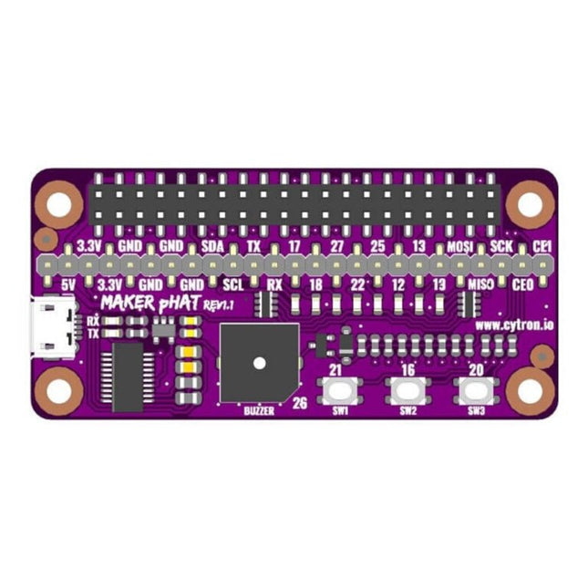
The Maker pHAT is the solution to the most common problems beginners face starting with Raspberry PI. Its intelligent and simple design makes it easy to attach to your Pi, and it helps you avoid all the tedious work of connection various other accessories. Additionally, the LEDs corresponding to each pin makes it extremely easy to see where a potential problem lies
The Maker pHat has the same size as the Raspberry Pi Zero with all 4mounting holes aligned. However, it can be used with Raspberry Pi 3B, 3B+ and 3A+, by inserting a 2 x 20 stacking header.
Kenmerken
Raspberry Pi Zero size, stack perfectly on to Raspberry Pi Zero
Compatible with standard size Raspberry Pi 3B / 3B+, medium size Raspberry Pi 3A+ and smaller size Raspberry Pi Zero / W / WH.
Standard Raspberry Pi GPIO footprint.
LED array for selected GPIO pins (GPIO 17, 18, 27, 22, 25, 12, 13, 19).
3x on board programmable push buttons (GPIO 21, 19 and 20, need to configure as input pull up).
Onboard active buzzer (GPIO 26).
Proper labels for all GPIOs, including SPI, UART, I2C, 5V, 3.3V, and GND.
Utilize USB Micro-B socket for 5V input and USB to UART communication.
USB serial facilitated by the FT231X
Input voltage: USB 5 V, from a computer, power bank or a standard USB adapter.
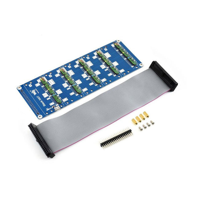
This is an I/O expansion kit designed for Raspberry Pi, which provides 5 sets of 2x20 pinheaders, that means a handy way to 'stack' multi different HATs together, and use them as a specific combination / project. Features Standard Raspberry Pi connectivity, directly pluggable OR through ribbon cable 5 sets of 2x20 pinheaders, connect multi HATs together USB external power port, provides enough power supply for multi HATs Clear and descriptive pin labels for easy use Reserved jumper pads on the bottom side, pin connections are changeable by soldering, to avoid pin conflicts Note: make sure there are no any pin conflicts between the HATs you want to use together before connecting. Specifications Dimensions: 183 × 65 mm Mounting hole size: 3 mm Included 1x Stack HAT 1x Ribbon cable 40-Pin 1x 2x20 male pinheader 1x RPi screws pack (4pcs) x1
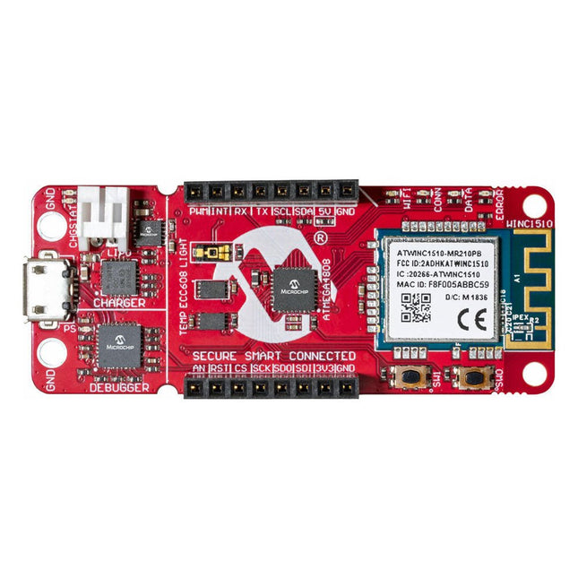
The AVR-IoT WA development board combines a powerful ATmega4808 AVR MCU, an ATECC608A CryptoAuthentication™ secure element IC and the fully certified ATWINC1510 Wi-Fi network controller – which provides the most simple and effective way to connect your embedded application to Amazon Web Services (AWS). The board also includes an on-board debugger, and requires no external hardware to program and debug the MCU.Out of the box, the MCU comes preloaded with a firmware image that enables you to quickly connect and send data to the AWS platform using the on-board temperature and light sensors. Once you are ready to build your own custom design, you can easily generate code using the free software libraries in Atmel START or MPLAB Code Configurator (MCC).The AVR-IoT WA board is supported by two award-winning Integrated Development Environments (IDEs) – Atmel Studio and Microchip MPLAB X IDE – giving you the freedom to innovate with your environment of choice.Features
ATmega4808 microcontroller
Four user LED’s
Two mechanical buttons
mikroBUS header footprint
TEMT6000 Light sensor
MCP9808 Temperature sensor
ATECC608A CryptoAuthentication™ device
WINC1510 WiFi Module
On-board Debugger
Auto-ID for board identification in Atmel Studio and Microchip MPLAB X
One green board power and status LED
Programming and debugging
Virtual COM port (CDC)
Two DGI GPIO lines
USB and battery powered
Integrated Li-Ion/LiPo battery charger
Een door een Pico W bestuurde alles-in-één industriële automatiseringscontroller met 2,46 GHz draadloze connectiviteit, diverse relais, en een overvloed aan in- en uitgangen. Hij is compatibel met systemen van 6 V tot 40 V.De Automation 2040 W is een door een Pico W / RP2040 bestuurde bewaking- en automatiseringsboard. Hij bevat alle uitstekende functies van de Automation HAT (relais, analoge kanalen, met spanning gevoede uitgangen, en gebufferde ingangen), maar nu op één compact bordje en met een breder spanningsbereik, zodat je hem met meer apparaten kunt gebruiken. Zeer geschikt voor het aansturen van ventilatoren, pompen, elektromagneten, grote motoren, elektronische sloten of statische LED-verlichting (tot 40 V).Alle kanalen (en de knoppen) hebben een bijbehorende indicatie-LED, zodat je in één oogopslag kunt zien wat er met je setup gebeurt, of waarmee je programma's kunt testen zonder dat er hardware is aangesloten.Kenmerken
De Raspberry Pi Pico W op het board
Dual Arm Cortex M0+ die op maximaal 133 MHz draait met 264 KB SRAM
2 MB QSPI flash die XiP ondersteunt
Gevoed en programmeerbaar via USB Micro-B
2,4 GHz draadloos
3x 12-bits ADC-ingangen tot 40 V
4x digitale ingangen tot 40 V
3x digitale sourcing uitgangen op V+ (voedingsspanning)
4 A maximale continue stroom
2 A max stroom bij 500 Hz PWM
3x relais (NC- en NO-klemmen)
2 A tot 24 V
1 A tot 40 V
3,5 mm schroefklemmen voor het aansluiten van ingangen, uitgangen en externe voeding
2x knopschakelaars met LED-indicatoren
Reset knop
2x Qw/ST connectoren voor het bevestigen van breakouts
M2,5 montage gaten
Volledig geassembleerd
Solderen is niet nodig.
C/C++ en MicroPython libraries
Schema
Lay-out
Voeding
Board is compatibel met 12 V, 24 V en 36 V systemen
Vereist een voeding van 6-40 V
Kan 5 V tot 0,5 A leveren voor toepassingen met een lagere spanning
Downloads
Pirate-brand MicroPython
Aan de slag met de Raspberry Pi Pico
MicroPython voorbeelden
MicroPython functie referentie
C++ voorbeelden
C++ functie referentie
Aan de slag met de Automation 2040 W
De SparkFun GPS-RTK2 verhoogt de lat voor hoge precisie GPS en is de nieuwste in een reeks van krachtige RTK kaarten met de ZED-F9P module van u-blox. De ZED-F9P is een top-of-the-line module voor hoge nauwkeurigheid GNSS en GPS locatie-oplossingen, met inbegrip van RTK in staat tot 10mm, drie-dimensionale nauwkeurigheid. Met deze kaart, zult u in staat zijn om te weten waar uw (of een object) X, Y, en Z locatie is binnen ruwweg de breedte van uw vingernagel! De ZED-F9P is uniek omdat hij zowel als rover als basis station kan werken. Door gebruik te maken van ons handige Qwiic systeem, hoeft u niet te solderen om hem aan te sluiten op de rest van uw systeem. We hebben echter nog steeds 0,1'-spaced pinnen als u liever een breadboard gebruikt. We hebben zelfs een oplaadbare backupbatterij ingebouwd om de laatste moduleconfiguratie en satellietgegevens tot twee weken lang beschikbaar te houden. Deze batterij helpt bij het 'warm-starten' van de module, waardoor de tijd tot de eerste fix drastisch wordt verkort. Deze module beschikt over een survey-in modus waardoor de module een basisstation kan worden en RTCM 3.x correctiegegevens kan produceren. Het aantal configuratiemogelijkheden van de ZED-F9P is ongelofelijk! Geofencing, variabel I2C-adres, variabele updatefrequenties, zelfs de hoge precisie RTK-oplossing kan worden verhoogd tot 20Hz. De GPS-RTK2 heeft zelfs vijf communicatiepoorten die allemaal tegelijk actief zijn: USB-C (die als COM-poort wordt geteld), UART1 (met 3,3V TTL), UART2 voor RTCM-ontvangst (met 3,3V TTL), I2C (via de twee Qwiic-connectoren of uitgevallen pinnen), en SPI. Sparkfun heeft ook een uitgebreide Arduino bibliotheek voor u-blox modules geschreven om de GPS-RTK2 gemakkelijk uit te lezen en te besturen via het Qwiic Connect System. Laat NMEA achter! Begin met het gebruik van een veel lichter gewicht binaire interface en geef je microcontroller (en zijn ene seriële poort) een pauze. De SparkFun Arduino bibliotheek laat zien hoe je breedtegraad, lengtegraad, zelfs koers en snelheid over I2C kunt lezen zonder de noodzaak van constante seriële polling. Features Parallel ontvangst van GPS, GLONASS, Galileo en BeiDou Ontvangt zowel L1C/A als L2C banden Spanning: 5 V of 3,3 V, maar alle logica is 3,3 V Stroom: 68 mA - 130 mA (varieert met constellaties en volgstatus) Tijd tot eerste fix: 25 s (koud), 2 s (warm) Maximale navigatiesnelheid: PVT (basis locatie over UBX binair protocol) - 25 Hz RTK - 20 Hz Raw - 25 Hz Horizontale Positie Nauwkeurigheid: 2,5 m zonder RTK 0,010 m met RTK Max Hoogte: 50k m Max Snelheid: 500 m/s Gewicht: 6.8 g Afmetingen: 43,5 mm x 43,2 mm 2 x Qwiic aansluitingen
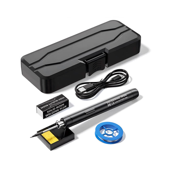
De Smart USB Soldeerbout Kit is een compacte, draadloze oplossing, ontworpen voor precisie en draagbaarheid. Met intelligente temperatuurregeling met drie snelheden (300-450°C) en een gemakkelijk afleesbaar LED-display, warmt hij op in slechts 10 seconden en smelt het soldeer in slechts 6 seconden.
De oplaadbare batterij van 1000 mAh biedt tot 30 minuten continu gebruik, waardoor hij ideaal is voor snelle reparaties, elektronicaprojecten en doe-het-zelfklussen. Met een plug-and-play, vervangbare punt en een hittebestendige, geïsoleerde behuizing is hij veilig, gebruiksvriendelijk en perfect voor zowel beginners als professionals onderweg.
Kenmerken
Intelligente temperatuurregeling met drie snelheden: Voorzien van een led-display met instelbare temperaturen tussen 300 en 450°C. Schakel eenvoudig tussen Celsius en Fahrenheit.
Geïntegreerde plug-in soldeerboutpunt: Plug-and-play ontwerp. De punt kan worden vervangen door deze eenvoudig los te draaien, voor een snelle en gemakkelijke bediening.
Veilig en duurzaam ontwerp: Hittebestendige, geïsoleerde behuizing voor extra veiligheid tijdens gebruik.
Batterijcapaciteit: Uitgerust met een oplaadbare batterij van 1000 mAh die tot 30 minuten continu gebruik ondersteunt op een volle lading – ideaal voor dagelijkse taken.
Efficiënte prestaties: 8 W vermogen met een geïntegreerde verwarmingskern voor snelle opwarming. Smelt tin in slechts 6 seconden en biedt uitstekende thermische geleiding.
Gebruiksvriendelijk: Na het inschakelen via USB stelt u de gewenste temperatuur in. De soldeerbout warmt op in 10 seconden. Zodra de soldeerbout klaar is, plaatst u de punt op de standaard – deze koelt binnen 1 minuut af. Perfect voor beginners, hobbyisten, eenvoudige klusjes in huis en het opleiden van ingenieurs.
Draadloze innovatie: Deze draadloze soldeerset bevat een ingebouwde oplaadbare lithium-ionbatterij, waardoor kabels niet meer nodig zijn. Veelzijdig te gebruiken voor het solderen van printplaten, elektrische reparaties, het maken van sieraden, metaalbewerking, computeronderhoud en doe-het-zelfprojecten.
Specificaties
Instelbare temperatuur: 300-450°C
Smelttijd tin: <15 seconden
Werkspanning: 5 V
Uitgangsvermogen: 8 W
Batterijcapaciteit: 1000 mAh
Automatische slaapfunctie: Activeert na 10 minuten inactiviteit
Oplaadtijd: ca. 90 minuten
Batterijduur: Tot 30 minuten continu gebruik
Oplaadinterface: USB-C
Materiaal: Aluminiumlegering
Afmetingen: 190 x 16 mm
Inbegrepen
1x USB Soldeerbout
1x Soldeerpunt
1x Soldeerhars
1x Soldeerbouthouder (met spons)
1x USB-C oplaadkabel
1x Soldeerdraad
1x Opbergdoos
De AD584 4-kanaals spanningsreferentiemodule is ontworpen om stabiele en nauwkeurige referentiespanningen van 2,5 V, 5 V, 7,5 V en 10 V te leveren. Het bevat het AD584 geïntegreerde circuit, bekend om zijn hoge nauwkeurigheid en stabiliteit.
Kenmerken
Meerdere uitgangsspanningen: De module kan vier verschillende referentiespanningen (2,5 V, 5 V, 7,5 V en 10 V) afgeven die toegankelijk zijn via een enkele poort.
Microcontroller-gebaseerde schakeling: Een ingebouwde microcontroller vergemakkelijkt het schakelen tussen de vier spanningsuitgangen, met LED-indicatoren die de actieve selectie weergeven.
Gebruiksvriendelijke bediening: Een enkele knop maakt het mogelijk om eenvoudig door de beschikbare referentiespanningen te bladeren.
Transparante behuizing: De module is omhuld door een transparante behuizing, die bescherming biedt terwijl gebruikers de interne componenten kunnen bekijken.
Voedingsopties: Het kan worden gevoed via een ingebouwde lithiumbatterij (niet meegeleverd) of via een 5 V DC-ingang. Een laadindicator geeft statusupdates tijdens het opladen.
Uitvoerinterface: Uitgerust met 4mm-banaanaansluitingen voor veilige en betrouwbare verbindingen.
Inbegrepen
1x AD584 4-kanaals spanningsreferentiemodule met behuizing
Downloads
Datasheet
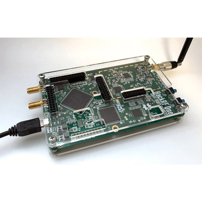
Deze doorzichtige acryl behuizing is de officiële behuizing voor het HackRF One-board. Hij kan de standaard zwarte plastic behuizing van de HackRF One vervangen.
Montage-instructies
Gebruik een plectrum of spudger om de HackRF One printplaat uit de zwarte plastic behuizing te halen.
Steek een lange schroef in elke hoek van het onderste acrylpaneel. Zet elke lange schroef vast met een kort afstandsstuk (5 mm) aan de tegenoverliggende kant van het paneel.
Plaats de HackRF One printplaat (naar boven gericht) bovenop het onderpaneel en steek de uiteinden van de lange schroeven door de bevestigingsgaten in de hoeken van de print.
Zet de printplaat vast met een lang afstandsstuk (6 mm) in elke hoek.
Plaats het bovenste acrylpaneel op de printplaat en lijn de uitsparingen uit met de extension headers op de print.
Zet elke hoek vast met een korte schroef.
Opmerking: Niet te strak aandraaien! Na elke stap alleen met de hand aandraaien.
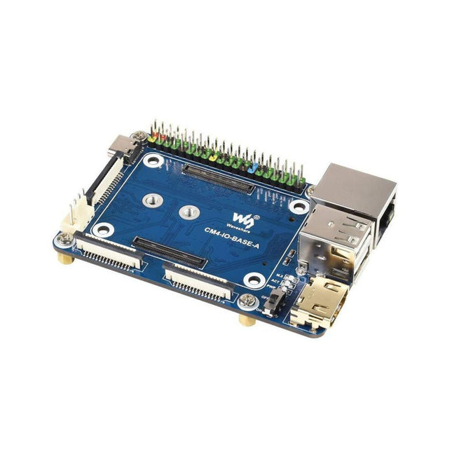
Specifications CM4 socket Suitable for all variants of Compute Module 4 Networking Gigabit Ethernet RJ45 connectorM.2 M KEY, supports communication modules or NVME SSD Connector Raspberry Pi 40-PIN GPIO header USB 2x USB 2.0 Type A2x USB 2.0 via FFC connector Display MIPI DSI display port (15-pin 1.0 mm FPC connector) Camera 2x MIPI CSI-2 camera port (15-pin 1.0 mm FPC connector) Video 2x HDMI port (including one port via FFC connector), supports 4K 30fps output RTC N/A Storage MicroSD card socket for Compute Module 4 Lite (without eMMC) variants Fan header No fan control, 5 V Power input 5 V Dimensions 85 x 56 mm Included 1x CM4-IO-BASE-A 1x SSD mounting screw Downloads Wiki
Add colors to your projects with this collection of red, green, yellow, blue and white LEDs. They come with various current limiting resistors in order to protect the parts and control the brightness.Included
10 mm LEDs
1x red
1x green
1x yellow
1x blue
1x white
5 mm LEDs
5x red
5x green
5x yellow
5x blue
5x white
3 mm LEDs
5x red
5x green
5x yellow
5x blue
5x white
25x 330 Ω resistors
10x 1 kΩ resistors
10x 10 kΩ resistors
10x 100 kΩ resistors
10x 1 MΩ resistors
Entièrement mise à jour pour le Raspberry Pi 5
Raspberry Pi 5 est un petit ordinateur intelligent, de construction britannique qui regorge de potentiel. Fabriqué à l'aide d'un processeur économe en énergie, le Raspberry Pi est conçu pour vous aider à apprendre le codage, découvrir comment fonctionne un ordinateur et construire vos propres projets uniques et incroyables. Ce guide est conçu pour vous montrer à quel point il est facile de démarrer.
Apprendre à :
Configurez votre Raspberry Pi, installez son système d'exploitation, et commencez à utiliser cet ordinateur entièrement fonctionnel.
Commencez à coder des projets, avec des guides étape par étape utilisant les langages de programmation Scratch 3, Python et MicroPython.
Expérimentez en connectant des composants électroniques, et amusez-vous à créer des projets incroyables.
Nouveauté de la 5ème édition :
Mise à jour pour les derniers ordinateurs Raspberry Pi : Raspberry Pi 5 et Raspberry Pi Zèro 2 W.
Couvre le dernier système d'exploitation Raspberry Pi.
Comprend un nouveau chapitre sur le Raspberry Pi Pico !
Téléchargements
GitHub