Zoekresultaten voor "ftdi l"
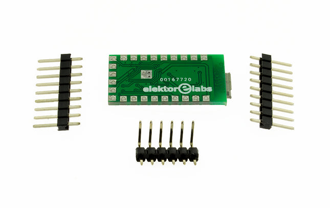
Elektor Labs USB-RS232 Converter (FT231X BoB)
In 2011 we published a small PCB, FT232R USB/Serial Bridge/BOB (110553) with a USB-UART IC from FTDI, the FT232RQ. Here we present its successor with a cheaper version, an FT231XQ. But there are some other changes too. Instead of connectors, alongside the PCB, normal pin headers are used that are mounted on the bottom side and make the PCB a little smaller when mounted, compared to the old BoB. An ESD protection device (D1) is added in the USB data signal lines for extra safety. Despite less room for all parts to fit on the PCB, it is only a little over 2 mm longer. The FT231 has four configurable CBUS I/O pins, one less now. More importantly, however, the power supply for the I/O's VCCIO is only specified for +1.8 V to +3.3 but is 5 V tolerant for external UART logic running on +5 V. The +3.3 V internal regulator of the FT231 can deliver 50 mA to external circuitry. The manufacturer FTDI has a utility to configure several settings, FTPROG. Such as the function of the CBUS pins. By default, CBUS1 and CBUS 2 are low-level outputs to drive receive and transmit LEDs, indicating data transfer on the USB bus. So, when receiving data through the UART, the TX LED lights up. If you prefer this the other way around, FTPROG can be used to change this. But be careful the chip can become unresponsive when wrong settings are programmed. Some of the more important properties of the new BoB: Micro-USB connector USB 2.0 Full Speed capable VCCIO +1.8...+3.3 V (max. 4 V, 5 V input from UART logic tolerant) +3.3 V regulator output, max. 50 mA Data transfer 300 baud to 3 Mbaud UART Compatible with RS232, RS485, and RS422 I/O pin output drive 4 mA - 16 mA 4 configurable CBUS pins Here you can find information regarding the EEPROM Programming Utility, the VCP Drivers and the D2XX Drivers.
€ 19,95
Leden € 17,96

Elektor Digital Programming the Finite State Machine (E-book)
Programming the Finite State Machine with 8-Bit PICs in Assembly and C Andrew Pratt provides a detailed introduction to programming PIC microcontrollers, as well as a thorough overview of the Finite State Machine (FSM) approach to programming. Most of the book uses assembly programming, but do not be deterred. The FSM gives a structure to a program, making it easy to plan, write, and modify. The last two chapters introduce programming in C, so you can make a direct comparison between the two techniques. The book references the relevant parts of the Microchip datasheet as familiarity with it is the best way to discover detailed information. This book is aimed at Microsoft Windows and Linux users. To keep your costs to a minimum and to simplify the toolchain, specific applications are provided as a free download to enable you to use an FTDI serial lead as the programmer. The assembler used is the open-source "gpasm". All programming can be done in a text editor. There are detailed instructions on how to perform the necessary installations on Windows, Linux Debian, and derivatives such as Ubuntu and Fedora. For programming in C, Microchip's XC8 compiler is used from the command line. In addition to the programming applications, two serial read and serial write applications can be used for communicating with the PICs from a computer. A voltmeter project including practical instructions on building a circuit board from scratch is included. All theory is covered beforehand, including how to do integer arithmetic in assembly. Two PICs are covered: the PIC12F1822 and the PIC16F1823. Both can run at 32 MHz with an internal oscillator. You do not need to buy a factory-made development board and programmer. With relatively inexpensive parts including a serial lead, microcontroller, a few resistors, and LEDs, you can get started exploring embedded programming. Links Updated Programmer
€ 27,95
Leden € 22,36
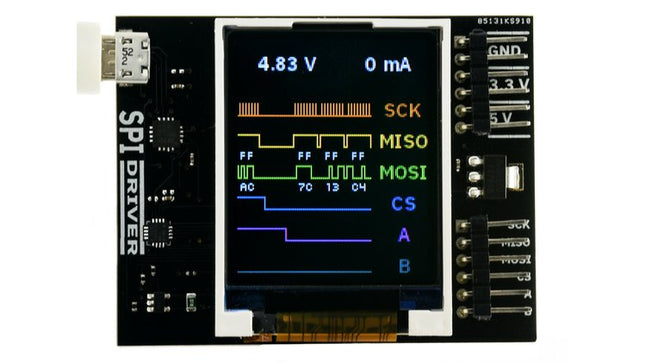
Excamera Labs SPIDriver
SPIDriver shows you what’s happening on the SPI bus in real time, so no more guessing about the bus state. Its purpose is to make understanding the functioning of SPI hardware more intuitive. It's useful if you're into debugging hardware or simply introduce a class to SPI for the first time.You can directly control LEDs and LCD displays just by having SPIDriver and you won't have to deal with microcontrollers. It's also a useful tool for examining, backing up and cloning an SPI flash as well as reading and writing SPI flash in circuit.SPIDriver is also applicable if you want to drive, test and evaluate different displays.With the help of current and voltage monitoring you'll be able to detect electrical problems at early stages. Thanks to the included color coded wires you can hook SPIDriver up without much effort; no pinout diagram required. It includes 3.3 V and 5 V supplies for your device, plus a high-side current meter.SPIDriver comes with software to control it from: a GUI the command-line C and C++ using a single source file Python 2 and 3, using a module Technical features Live display shows you exactly what it’s doing all the time Sustained SPI transfers at 500 Kbps USB line voltage monitor to detect supply problems, to 0.01 V Target device high-side current measurement, to 5 mA Two auxiliary output signals, A and B Two dedicated power outlines: of 3.3 V and 5 V All signals color coded to match jumper colors All signals are 3.3 V, and are 5 V tolerant Uses an FTDI USB serial adapter, and Silicon Labs automotive-grade EFM8 controller Also reports uptime, temperature, and running CRC of all traffic All sensors and signals controlled using a simple serial protocol GUI, command-line, C/C++, and Python 2/3 host software provided for Windows, Mac, and Linux Details Maximum power out current: up to 470 mA Signal current: up to 10 mA Device current: up to 25 mA Dimensions: 61 mm x 49 mm x 6 mm Interface: USB 2.0, micro USB connector Contents (SPIDriver Core) 1x SPIDriver 1x Set of hookup jumpers
€ 49,95
Leden € 44,96
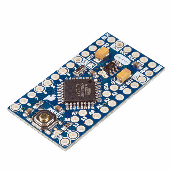
SparkFun SparkFun Arduino Pro Mini 328 (5 V, 16 MHz)
De Arduino Pro Mini is een microcontroller board gebaseerd op de ATmega328P.Het heeft 14 digitale in-/uitgangspinnen (waarvan er 6 kunnen worden gebruikt als PWM-uitgangen), 6 analoge ingangen, een on-board resonator, een reset-knop, en gaten voor het monteren van pin headers. Een six-pin header kan worden aangesloten op een FTDI-kabel of Sparkfun breakout board om USB-voeding en communicatie te bieden aan de board.De Arduino Pro Mini is bedoeld voor semi-permanente installatie in voorwerpen of tentoonstellingen. Het board komt zonder pre-gemonteerde headers, waardoor het gebruik van diverse types van schakelaars of het directe solderen van draden is toegestaan. De pin lay-out is compatibel met Arduino Mini.De Arduino Pro Mini werd ontworpen en wordt vervaardigd door SparkFun Electronics.SpecificatiesDownloads Eagle bestanden Schema's Microcontroller ATmega328P Boord Stroomvoorziening 5-12 V Circuit Werkspanning 5 V Digitale I/O Pinnen 14 PWM Pennen 6 UART 1 SPI 1 I²C 1 Analoge ingangspinnen 6 Externe Onderbrekingen 2 DC stroom per I/O Pin 40 mA Flash Geheugen 32 KB waarvan 2 KB gebruikt door bootloader SRAM 2 KB EEPROM 1 KB Kloksnelheid 16 MHz Afmetingen 18 x 33,3 mm
€ 14,95
Leden € 13,46
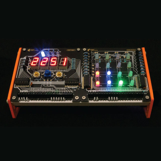
Short Circuits: The 4-Pack (Arduino-compatible Electronics Platform)
Get started with microcontroller based electronicsThis Arduino-compatible bundle contains the Motherboard, Digitiser, Sensor Array and RGB Matrix. With these 4 boards you have everything you need to build a clock, score counter, timer, task reminder, thermometer, humidity display, sound meter, light meter, clap trigger, colored bar graph display, animated alarm, and much more! The Motherboard has a built in real time clock module that keeps time even when unplugged. The Digitiser can display 4 digits or characters and includes 2 buttons and a potentiometer to let you control what’s being displayed, or the brightness of the display. The Sensor Array can read temperature, relative humidity, sound and light, with an SD card slot for data recording. The RGB Matrix has 16 RGB LEDs that are controlled through shift registers, so only use 3 or 4 pins of the Motherboard. MotherboardThe Motherboard is an Arduino-compatible microcontroller breakout board designed around the ATmega328P. The board comes in a solder-it-yourself kit with all the components you need to get started with microcontroller based electronics. All other boards connect to this. Based on the ATmega328P Arduino compatible On-Board RTC (Real Time Clock) FTDI Header for easy programming Bluetooth Header Terminal Block Connections DigitiserThe Digitiser is a versatile display and input board. It let’s you visualise your data. Show your sensor information, clock digits, or even keep score for your favourite card game. The Digitiser also includes some buttons and a knob to let you take control. 4x 7-Segment Displays Uses 595 Shift Registers 2 Switches and a Potentiometer 4 colored 'Mode' LEDs Chainable with other 595 Boards Terminal Block Connections Sensor ArrayAs the name suggests, the Sensor Array is an array of sensors. Measure temperature and relative humidity via the DHT11, light via the light dependant resistor, and sound via the microphone and amplifier circuit. Then you can log the data using the on-board SD card slot. DHT11 Temp & Humidity Sensor Microphone and Amplifier Circuit Light Dependent Resistor MicroSD Slot for Saving Data Logic Level Converter Circuit Terminal Block Connections RGB MatrixAdd color to your project by controlling 16 red, 16 green and 16 blue LEDs with just 3 pins of your microcontroller. The RGB Matrix uses shift registers, a matrix and switching transistors, so there’s plenty to learn and explore. 4x4 (16) RGB LEDs Uses 595 Shift Registers Chainable with other 595 Boards Transistor Switches Terminal Block Connections Downloads (Manuals) Motherboard Digitiser Sensor Array RGB Matrix
€ 99,95
Leden € 89,96
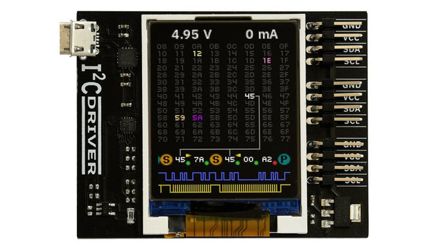
Excamera Labs I²CDriver
I²C is ubiquitous, you can find it in your phone, in embedded electronics, in all microcontrollers, Raspberry Pi and computer motherboards. It's applicable in a wide variety of cases, but the only downside is that it might be difficult to learn using it properly and to avoid painful debugging.This device makes it easier for you to understand what's going on inside, as I²CDriver has a clear logic-analyzer display of the signal lines plus a graphical decoding of the I²C traffic.In addition, it continuously displays an address map of all attached I²C devices, so as you connect a device, it lights up on the map.The current and voltage monitoring let you catch electrical problems early. The included color-coded wires make hookup quite easy; no pinout diagram is required. It includes a separate 3.3 V supply for your devices, a high-side current meter, and programmable pullup resistors for both I²C lines.Thanks to 3 I²C ports you can hook up multiple devices simultaneously without any effort. I²CDriver comes with software to control it from: a GUI the command-line C and C++ using a single source file Python 2 and 3, using a module You can control I²C hardware using the PC tools you’re familiar with and reduce the development time needed to get the device doing what you want it to.Calibrating devices like accelerometers, magnetometers, and gyroscopes is much simpler and faster when done directly on the PC through I²CDriver.Moreover, the built in display shows a heatmap of all active network nodes. So in an I²C network with multiple devices, you can see at a glance which ones are the most active.I²CDriver can dump all I²C traffic back to the PC. I²CDriver’s capture mode reliably records every bit to an exhaustive time-stamped log. This is really helpful for debug, analysis, and reverse-engineering. Supported formats include text, CSV, and VCD.Features Open hardware: the design, firmware and all tools are under BSD license Live display: shows you exactly what it’s doing all the time Fast transfer: sustained I²C transfers at 400 and 100 kHz USB power monitoring: USB line voltage monitor to detect supply problems, to 0.01 V Target power monitoring: target device high-side current measurement, to 5 mA I²C pullups: programmable I²C pullup resistors, with automatic tuning Three I²C ports: three identical I²C ports, each with power and I²C signals Jumpers: color coded jumpers included in each pledge level 3.3 output: output levels are 3.3 V, all are 5 V tolerant Supports all I²C features: 7- and 10-bit I²C addressing, clock stretching, bus arbitration Sturdy componentry: uses an FTDI USB serial adapter, and Silicon Labs automotive-grade EFM8 controller Usage reporting: reports uptime, temperature, and running CRC of all traffic Flexible control: GUI, command-line, C/C++, and Python 2/3 host software provided for Windows, Mac, and Linux Details Maximum power out current: up to 470 mA Device current: up to 25 mA Dimensions: 61 mm x 49 mm x 6 mm Computer interface: USB 2.0, micro USB connector Contents (I²CDriver Core) 1x I²CDriver 3x Set of hookup jumpers


