Zoekresultaten voor "feather"
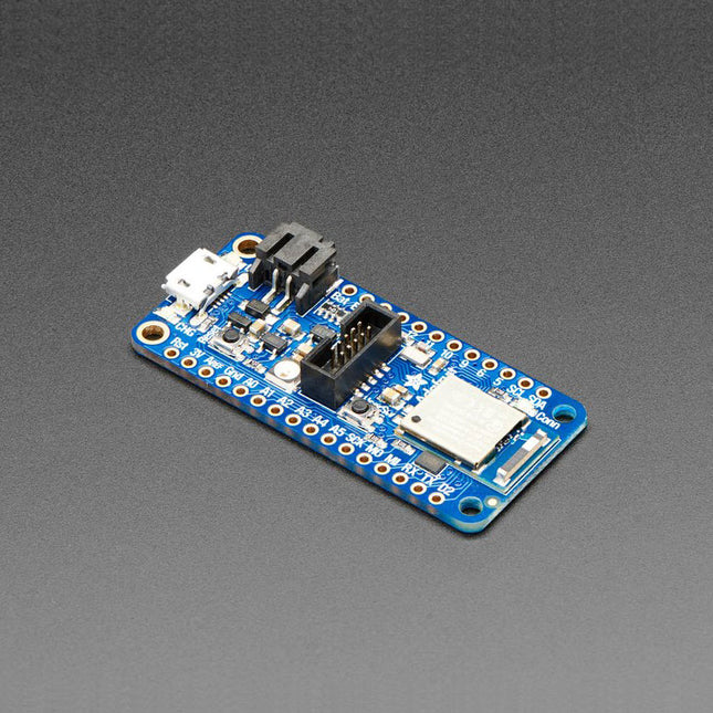
Adafruit Adafruit Feather nRF52840 Express
U kunt de nRF52840 chip direct programmeren om optimaal gebruik te maken van de Cortex-M4 processor, en vervolgens de Nordic SoftDevice radio stack aanroepen wanneer u moet communiceren via BLE. Aangezien de onderliggende API en randapparatuur hetzelfde zijn voor de '832 en '840, kunt u uw oudere nRF52832 projecten superchargen met exact dezelfde code, met een enkele hercompilatie! CircuitPython werkt het beste met schijf-toegang, en dit is de enige BLE-plus-USB-native chip die het geheugen heeft om een kleine Python-interpreter te laten draaien. Het enorme RAM geheugen en de snelle Cortex M4F chip maken dit een goede match.PeripheralsVeel GPIO, analoge ingangen, PWM, timers, enz. En het beste van alles, het heeft USB! Eindelijk, geen noodzaak voor een aparte USB seriële chip zoals CP2104 of FT232. Serieel wordt behandeld als een USB CDC descriptor, en de chip kan werken als een toetsenbord, muis, MIDI-apparaat, of zelfs disk drive. Deze chip heeft TinyUSB ondersteuning - dat betekent dat u het met Arduino als een native USB-apparaat kunt gebruiken en als UART (CDC), HID, Massa-opslag, MIDI, en meer fungeren! Features ARM Cortex M4F (met HW drijvende komma versnelling) draait op 64 MHz 1 MB flash en 256 KB SRAM Native Open Source USB stack (voorgeprogrammeerd met UF2 bootloader) Bluetooth Low Energy compatibele 2.4 GHz radio FCC / IC / TELEC gecertificeerde module Tot +8 dBm uitgangsvermogen 1,7 V tot 3,3 V werking met interne lineaire en DC/DC-spanningsregelaars 21 GPIO, 6x 12-bit ADC pinnen, tot 12 PWM uitgangen (3 PWM modules met elk 4 uitgangen) Pin #3 rode LED voor algemeen knipperen, NeoPixel voor kleurrijke feedback Pin voor voeding/inschakelen Afmetingen 2.0 x 0.9 x 0.28 '(51 x 23 x 7.2 mm) zonder headers gesoldeerd Licht als een (grote?) veertje (6 gram) 4 bevestigingsgaten Reset knop SWD-aansluiting voor debuggen
€ 32,95
Leden € 29,66
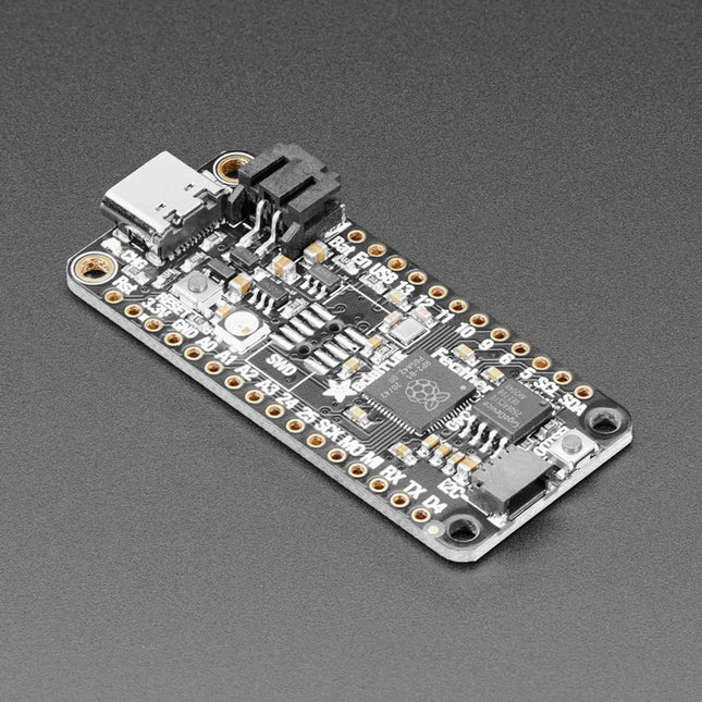
Adafruit Adafruit Feather RP2040
Inside the RP2040 is a 'permanent ROM' USB UF2 bootloader. What that means is when you want to program new firmware, you can hold down the BOOTSEL button while plugging it into USB (or pulling down the RUN/Reset pin to ground) and it will appear as a USB disk drive you can drag the firmware onto. Folks who have been using Adafruit products will find this very familiar – Adafruit uses the technique on all thier native-USB boards. Just note you don't double-click reset, instead hold down BOOTSEL during boot to enter the bootloader!The RP2040 is a powerful chip, which has the clock speed of our M4 (SAMD51), and two cores that are equivalent to our M0 (SAMD21). Since it is an M0 chip, it does not have a floating point unit, or DSP hardware support – so if you're doing something with heavy floating-point math, it will be done in software and thus not as fast as an M4. For many other computational tasks, you'll get close-to-M4 speeds!For peripherals, there are two I²C controllers, two SPI controllers, and two UARTs that are multiplexed across the GPIO – check the pinout for what pins can be set to which. There are 16 PWM channels, each pin has a channel it can be set to (ditto on the pinout).Technical Specifications Measures 2.0 x 0.9 x 0.28' (50.8 x 22.8 x 7 mm) without headers soldered in Light as a (large?) feather – 5 grams RP2040 32-bit Cortex M0+ dual core running at ~125 MHz @ 3.3 V logic and power 264 KB RAM 8 MB SPI FLASH chip for storing files and CircuitPython/MicroPython code storage. No EEPROM Tons of GPIO! 21 x GPIO pins with following capabilities: Four 12 bit ADCs (one more than Pico) Two I²C, Two SPI and two UART peripherals, one is labeled for the 'main' interface in standard Feather locations 16 x PWM outputs - for servos, LEDs, etc The 8 digital 'non-ADC/non-peripheral' GPIO are consecutive for maximum PIO compatibility Built in 200 mA+ lipoly charger with charging status indicator LED Pin #13 red LED for general purpose blinking RGB NeoPixel for full color indication. On-board STEMMA QT connector that lets you quickly connect any Qwiic, STEMMA QT or Grove I²C devices with no soldering! Both Reset button and Bootloader select button for quick restarts (no unplugging-replugging to relaunch code) 3.3 V Power/enable pin Optional SWD debug port can be soldered in for debug access 4 mounting holes 24 MHz crystal for perfect timing. 3.3 V regulator with 500mA peak current output USB Type C connector lets you access built-in ROM USB bootloader and serial port debugging RP2040 Chip Features Dual ARM Cortex-M0+ @ 133 MHz 264 kB on-chip SRAM in six independent banks Support for up to 16 MB of off-chip Flash memory via dedicated QSPI bus DMA controller Fully-connected AHB crossbar Interpolator and integer divider peripherals On-chip programmable LDO to generate core voltage 2 on-chip PLLs to generate USB and core clocks 30 GPIO pins, 4 of which can be used as analog inputs Peripherals 2 UARTs 2 SPI controllers 2 I²C controllers 16 PWM channels USB 1.1 controller and PHY, with host and device support 8 PIO state machines Comes fully assembled and tested, with the UF2 USB bootloader. Adafruit also tosses in some header, so you can solder it in and plug it into a solderless breadboard.
€ 16,95
Leden € 15,26
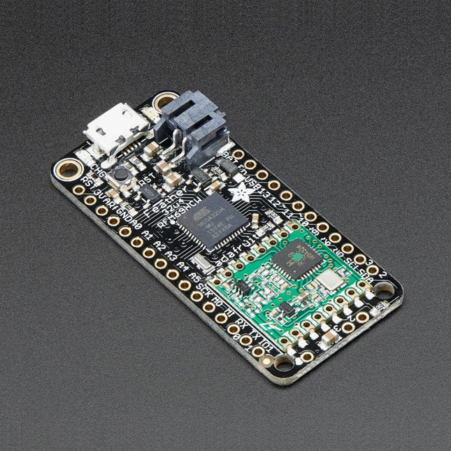
Adafruit Adafruit Feather 32u4 RFM69HCW Packet Radio (868 or 915 MHz) RadioFruit
Deze 900 MHz radio-versie kan worden gebruikt voor 868 MHz of 915 MHz transmissie/ontvangst – de exacte radiofrequentie wordt bepaald wanneer u de software laadt omdat deze dynamisch kan worden afgestemd.In het hart van de Feather 32u4 zit een ATmega32u4, geklokt op 8 MHz en op 3,3 V logica. Deze chip heeft 32 K flash en 2 K RAM, met ingebouwde USB, dus niet alleen heeft het een USB-naar-Serieel programma & debug mogelijkheid ingebouwd zonder noodzaak voor een FTDI-achtige chip, het kan ook fungeren als een muis, toetsenbord, USB MIDI-apparaat, enz.Om het gemakkelijk te gebruiken te maken voor draagbare projecten, hebben we een connector toegevoegd voor elke 3.7 V Lithium polymeer batterij en ingebouwd om de batterij op te laden. Je hebt geen batterij nodig, hij werkt prima rechtstreeks vanaf de micro USB connector. Maar als u wel een batterij hebt, kunt u die meenemen op reis en dan de USB aansluiten om op te laden. De Feather schakelt automatisch over op USB-voeding als die beschikbaar is. We hebben ook de batterij via een deler verbonden met een analoge pin, zodat je de batterijspanning kunt meten en monitoren om te detecteren wanneer je moet opladen.Functies Afmetingen 2.0' x 0.9' x 0.28' (51 x 23 x 8 mm) zonder headers erin gesoldeerd Licht als een (grote?) veertje - 5,5 gram ATmega32u4 @ 8 MHz met 3,3 V logica/voeding 3.3 V regulator met 500 mA piekstroomuitgang USB native ondersteuning, wordt geleverd met USB bootloader en seriële poort debugging U krijgt ook een heleboel pinnen - 20 GPIO-pinnen Hardware seriële, hardware I²C, hardware SPI-ondersteuning 7x PWM pinnen 10x analoge ingangen Ingebouwde 100 mA lipoly lader met oplaadstatus indicator LED Pin # 13 rode LED voor algemeen knipperen Voeding/contactpin 4 bevestigingsgaten Reset-knop De Feather 32u4 Radio gebruikt de extra ruimte die over is om een RFM69HCW 868/915 MHz radiomodule toe te voegen. Deze radio's zijn niet goed voor het overbrengen van audio of video, maar ze werken wel goed voor het verzenden van kleine datapakketjes als je meer bereik nodig hebt dan 2,4 GHz (BT, BLE, WiFi, ZigBee) SX1231 gebaseerde module met SPI interface Packet radio met kant-en-klare Arduino bibliotheken Gebruikt de licentievrije ISM-band ('Europese ISM' @ 868 MHz of 'Amerikaanse ISM' @ 915 MHz) +13 tot +20 dBm tot 100 mW uitgangsvermogen (uitgangsvermogen selecteerbaar in software) 50 mA (+13 dBm) tot 150 mA (+20 dBm) stroomverbruik voor transmissies Bereik van ca. 350 meter, afhankelijk van obstructies, frequentie, antenne en uitgangsvermogen Meerpuntsnetwerken met individuele knooppuntadressen maken Geëncrypteerde packet engine met AES-128 Eenvoudige draadantenne of spot voor uFL-connector Komt volledig geassembleerd en getest, met een USB bootloader waarmee je het snel kunt gebruiken met de Arduino IDE. Er worden ook koppen meegeleverd zodat je hem kan solderen en in een soldeerloos breadboard kan steken. U zult een klein stukje draad moeten knippen en solderen (elke vaste of vaste kern is prima) om uw antenne te maken.Lipoly batterij en USB kabel niet inbegrepen.
€ 34,95
Leden € 31,46
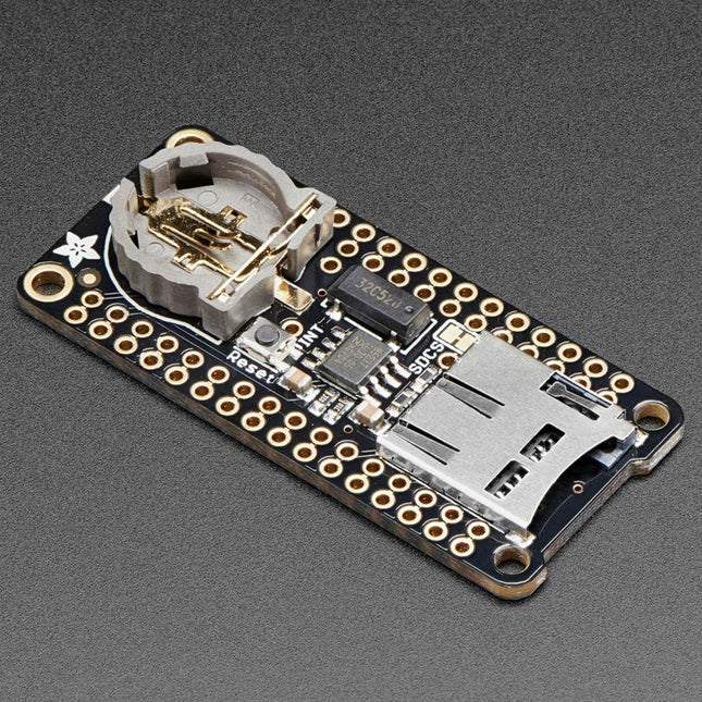
Adafruit Adafruit Adalogger FeatherWing (RTC + SD Add-on)
Deze FeatherWing maakt het eenvoudig om data logging toe te voegen aan elk Feather Board dat je hebt. U krijgt zowel een I²C real-time klok (PCF8523) met 32 KHz kristal en batterij back-up, en een microSD-aansluiting die verbinding maakt met de SPI-poort pinnen (+ extra pin voor CS). Note: FeatherWing wordt niet geleverd met een microSD-kaart.Een CR1220-muntcel is vereist om de RTC-batterij back-upmogelijkheden te gebruiken. Als u het RTC-gedeelte van de FeatherWing niet gebruikt, is een batterij niet nodig.Om met de microSD-kaartsocket te kunnen praten Worduino's standaard SD-bibliotheek wordt aanbevolen. Een beetje soldeerwerk is nodig om de headers op de Wing aan te brengen. PinoutsVoedingspennenOp de onderste rij worden de pinnen 3,3 V (tweede van links) en GND (vierde van links) gebruikt om de SD-kaart en de RTC van stroom te voorzien (om de knoopcelbatterij te ontlasten wanneer de netvoeding beschikbaar is)RTC & I²C-pennenIn de rechterbovenhoek worden SDA (meest rechts) en SCL (links van SDA) gebruikt om met de RTC-chip te praten. SCL - I²C-klokpen om aan te sluiten op de I2C-kloklijn van uw microcontroller. Deze pin heeft een pull-up weerstand van 10 k? naar 3,3 V SDA - I²C-datapin om aan te sluiten op de I2C-datalijn van uw microcontroller. Deze pin heeft een pull-up weerstand van 10 k? naar 3,3 V Er is ook een breakout voor INT, de uitgangspen van de RTC. Hij kan worden gebruikt als interrupt-uitgang of om een blokgolf te genereren.Merk op dat deze pin een open drain is - u moet de interne pull-up inschakelen op de digitale pin waarmee hij verbonden is. SD & SPI Pinnenbeginnend vanaf links heb je SPI Klok (SCK) - uitgang van veer naar vleugel SPI Master Out Slave In (MOSI) - uitgang van veer naar vleugel SPI Master In Slave Out (MISO) - ingang van vleugel naar veer Deze pinnen zitten op elke Feather op dezelfde plaats. Ze worden gebruikt voor de communicatie met de SD-kaart. Als de SD-kaart niet is geplaatst, zijn deze pinnen volledig vrij. MISO wordt tri-stated wanneer de SD CS (chip select) pin hoog wordt getrokken
€ 10,95
Leden € 9,86
Elektor Digital Initiation au langage CircuitPython et à la puce nRF52840 (E-book)
Le langage de programmation Python est apprécié par les pédagogues parce que sa syntaxe le rend facile à comprendre. Il s?est également imposé chez les informaticiens expérimentés. La société Adafruit a développé une version spéciale de Python pour l?embarquer sur les microcontrôleurs à 32 bits : CircuitPython. Ce livre permettra au lecteur de s?initier à la programmation en CircuitPython sur deux cartes : Feather BlueFruit Sense (également appelée Feather nRF52840 Sense) et CLUE nRF52840 Express. Chacune est animée par le SoC nRF52840 de NORDIC avec une architecture à 32 bits. Pour ce voyage dans le monde de la programmation embarquée, l?auteur sort du chemin classique, à savoir un cours complet sur la programmation orientée objet appliquée à ce langage. Il préfère emmener le lecteur directement sur le terrain avec des projets qui mettent en oeuvre les cartes et différents périphériques. Plus d?une quarantaine d?exemples et de montages permettent de découvrir la richesse de CircuitPython. Toutefois l?auteur s?est imposé une limite pour ne pas décourager les novices : le code de chaque projet ne dépasse jamais la centaine de lignes. Pour ce qui est du matériel, là aussi la simplicité domine : aucun programmateur, un simple PC suffit ; aucun soudage grâce au câblage sur platine d?essai. Les cartes d?extension FeatherWing à enficher sur la Feather nRF52840 Sense permettent de démultiplier ses fonctions : matrice de LED, enregistreur de données, écran à encre électronique, écran OLED, écran TFT, commande de moteurs, audio, relais? Toutes les étapes (assemblage des différents composants, installation des bibliothèques requises, programmation, tests?) sont expliquées en détail. Le code des différents exemples et projets est disponible sur Github. Le résultat de chaque projet est même présenté sur de courtes vidéos disponibles sur YouTube. À la fin de sa lecture, le nouveau Pythonien pourra facilement approfondir les notions abordées et donner vie à ses propres projets grâce aux outils qu?il aura essayés. Ce livre s?adresse aux lycéens et étudiants ainsi qu?à toute la communauté des makers. Chaîne YouTube de l?auteur : YouTube (Michaël Bottin)
€ 32,95
Leden € 26,36
SparkFun SparkFun RP2040 mikroBUS Development Board
The SparkFun RP2040 mikroBUS Development Board is a low-cost, high performance platform with flexible digital interfaces featuring the Raspberry Pi Foundation's RP2040 microcontroller. Besides the Thing Plus or Feather PTH pin layout, the board also includes a microSD card slot, 16 MB (128 Mbit) flash memory, a JST single cell battery connector (with a charging circuit and fuel gauge sensor), an addressable WS2812 RGB LED, JTAG PTH pins, four (4-40 screw) mounting holes, our signature Qwiic connectors, and a mikroBUS socket. The mikroBUS standard was developed by MikroElektronika. Similar to Qwiic and MicroMod interfaces, the mikroBUS socket provides a standardized connection for add-on Click boards to be attached to a development board and is comprised of a pair of 8-pin female headers with a standardized pin configuration. The pins consist of three groups of communications pins (SPI, UART and I²C), six additional pins (PWM, Interrupt, Analog input, Reset and Chip select), and two power groups (3.3 V and 5 V). The RP2040 is supported with both C/C++ and MicroPython cross-platform development environments, including easy access to runtime debugging. It has UF2 boot and floating-point routines baked into the chip. While the chip has a large amount of internal RAM, the board includes an additional 16 MB of external QSPI flash memory to store program code. The RP2040 contains two ARM Cortex-M0+ processors (up to 133 MHz) and features: 264 kB of embedded SRAM in six banks 6 dedicated IO for SPI Flash (supporting XIP) 30 multifunction GPIO: Dedicated hardware for commonly used peripherals Programmable IO for extended peripheral support Four 12-bit ADC channels with internal temperature sensor (up to 0.5 MSa/s) USB 1.1 Host/Device functionality Features (SparkFun RP2040 mikroBUS Dev. Board) Raspberry Pi Foundation's RP2040 microcontroller 18 Multifunctional GPIO Pins Four available 12-bit ADC channels with internal temperature sensor (500kSa/s) Up to eight 2-channel PWM Up to two UARTs Up to two I²C buses Up to two SPI buses Thing Plus (or Feather) Pin Layout: 28 PTH Pins USB-C Connector: USB 1.1 Host/Device functionality 2-pin JST Connector for a LiPo Battery (not included): 500mA charging circuit 4-pin JST Qwiic Connector LEDs: PWR - Red 3.3V power indicator CHG - Yellow battery charging indicator 25 - Blue status/test LED (GPIO 25) WS2812 - Addressable RGB LED (GPIO 08) Buttons: Boot Reset JTAG PTH Pins 16MB QSPI Flash Memory µSD Card Slot mikroBUS Socket Dimensions: 3.7' x 1.2' Four Mounting Holes: 4-40 screw compatible Downloads Schematic Eagle Files Board Dimensions Hookup Guide Qwiic Info Page GitHub Hardware Repository
€ 19,95
Leden € 17,96
iLabs iLabs Challenger RP2040 NFC
The Challenger RP2040 NFC is a small embedded computer, equipped with an advanced on-board NFC controller (NXP PN7150), in the popular Adafruit Feather form factor. It is based on an RP2040 microcontroller chip from the Raspberry Pi Foundation which is a dual-core Cortex-M0 that can run on a clock up to 133 MHz. NFC The PN7150 is a full featured NFC controller solution with integrated firmware and NCI interface designed for contactless communication at 13.56 MHz. It is fully compatible with NFC forum requirements and is greatly designed based on learnings from previous NXP NFC device generation. It is the ideal solution for rapidly integrating NFC technology in any application, especially small embedded systems reducing Bill of Material (BOM). The integrated design with full NFC forum compliancy gives the user all the following features: Embedded NFC firmware providing all NFC protocols as pre-integrated feature. Direct connection to the main host or microcontroller, by I²C-bus physical and NCI protocol. Ultra-low power consumption in polling loop mode. Highly efficient integrated power management unit (PMU) allowing direct supply from a battery. Specifications Microcontroller RP2040 from Raspberry Pi (133 MHz dual-core Cortex-M0) SPI One SPI channels configured I²C Two I²C channel configured (dedicated I²C for the PN7150) UART One UART channel configured Analog inputs 4 analog input channels NFC module PN7150 from NXP Flash memory 8 MB, 133 MHz SRAM memory 264 KB (divided into 6 banks) USB 2.0 controller Up to 12 MBit/s full speed (integrated USB 1.1 PHY) JST Battery connector 2.0 mm pitch On board LiPo charger 450 mA standard charge current Dimensions 51 x 23 x 3,2 mm Weight 9 g Note: Antenna is not included. Downloads Datasheet Quick start example
€ 22,95€ 17,95
Leden identiek
SparkFun SparkFun Thing Plus (RP2040)
De RP2040 bevat twee ARM Cortex-M0+ processoren (tot 133MHz) en beschikt over: 264 kB ingebed SRAM in zes banken 6 speciale IOs voor SPI Flash (met ondersteuning voor XIP) 30 multifunctionele GPIOs: Specifieke hardware voor veelgebruikte periferie Programmeerbare IO voor uitgebreide periferie-ondersteuning Vier 12-bit ADC-kanalen met interne temperatuursensor (tot 0,5 MSa/s) USB 1.1 Host/Device-functionaliteit De RP2040 wordt ondersteund met C/C++ en MicroPython cross-platform ontwikkelomgevingen, inclusief eenvoudige toegang tot runtime debugging. Het heeft een UF2 boot ROM en floating-point routines ingebouwd in de chip. Terwijl de chip een groot intern RAM geheugen heeft, bevat de kaart een extra 16MB extern QSPI flash geheugen om programmacode op te slaan. Eigenschappen Raspberry Pi Foundation's RP2040 microcontroller 16MB QSPI Flash Geheugen JTAG PTH pinnen Thing Plus (of Feather) Form-Factor: 18 x Multifunctionele GPIO-pennen Vier 12-bit ADC kanalen met een interne temperatuursensor (500kSa/s) Tot acht 2-kanaals PWM Tot twee UART's Tot twee I2C-bussen Tot twee SPI-bussen USB-C-aansluiting: USB 1.1 Host/Device-functionaliteit 2-pins JST-aansluiting voor een LiPo-batterij (niet meegeleverd): 500mA laadcircuit Qwiic Aansluiting Druktoetsen: Boot Reset LEDs: PWR - Rode 3,3V voedingsindicatie CHG - Gele batterij laadindicatie 25 - Blauwe status/test-LED (GPIO 25) WS2812 - Adresseerbare RGB-LED (GPIO 08) Vier montagegaten: 4-40 schroefcompatibel Afmetingen: 2,3' x 0,9' RP2040 Kenmerken Dubbele Cortex M0+ processoren, tot 133 MHz 264 kB ingebed SRAM in 6 banken 6 speciale IOs voor QSPI flash, met ondersteuning voor execute in place (XIP) 30 programmeerbare IOs voor uitgebreide periferie-ondersteuning SWD-interface Timer met 4 alarmen Real-time clock (RTC) USB 1.1 Host/Device-functionaliteit Ondersteunde programmeertalen MicroPython C/C++
€ 19,95
Leden € 17,96
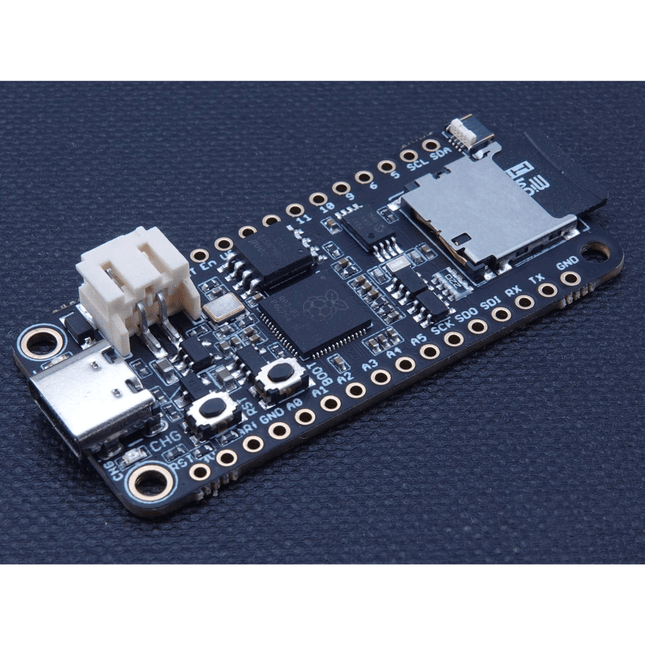
iLabs iLabs Challenger RP2040 SD/RTC
The Challenger RP2040 SD/RTC is an Arduino/CircuitPython compatible Adafruit Feather format microcontroller board based on the Raspberry Pi Pico chip. This board is equipped with an microSD card reader and a Real Time Clock making it super useful for data logging applications. MicroSD Card This board is equipped with a microSD card connector that will house standard microSD cards allowing your application to have many gigabytes of storage room for sensor data or what ever you want to place on it. Together with a fancy display you could also store cool images. Real Time Clock (RTC) MCP79410 is a highly integrated real time clock with nonvolatile memory and many other advanced features. These features include a battery switchover circuit for backup power, a timestamp to log power failures and digital trimming for accuracy. Using a low-cost 32.768 kHz crystal or other clock source, time is tracked in either a 12-hour or 24-hour format with an AM/PM indicator and timing to the second, minute, hour, day of the week, day, month and year. As an interrupt or wakeup signal, a multifunction open drain output can be programmed as an Alarm Out or as a Clock Out that supports 4 selectable frequencies. Specifications Microcontroller RP2040 from Raspberry Pi (133 MHz dual-core Cortex-M0) SPI One SPI channel configured I²C One I²C channel configured UART One UART channel configured Analog inputs 4 analog input channels Flash memory 8 MB, 133 MHz SRAM Memory 264 KB (divided into 6 banks) USB 2.0 controller Up to 12 MBit/s full speed (integrated USB 1.1 PHY) JST Battery connector 2.0 mm pitch On board LiPo charger 500 mA standard charge current RTC MCP79410 (uses I²C0 (Wire) for communication) SD Card One SPI channel used (uses SPI1 to connect to the SD socket) Dimensions 51 x 23 x 3,2 mm Weight 9 g Downloads Datasheet RunCPM image including HW I/O port support CPM File image for RunCPM Getting started with RunCPM for the Challenger RP2040 SD/RTC board CircuitPython download page
€ 17,95
Leden € 16,16
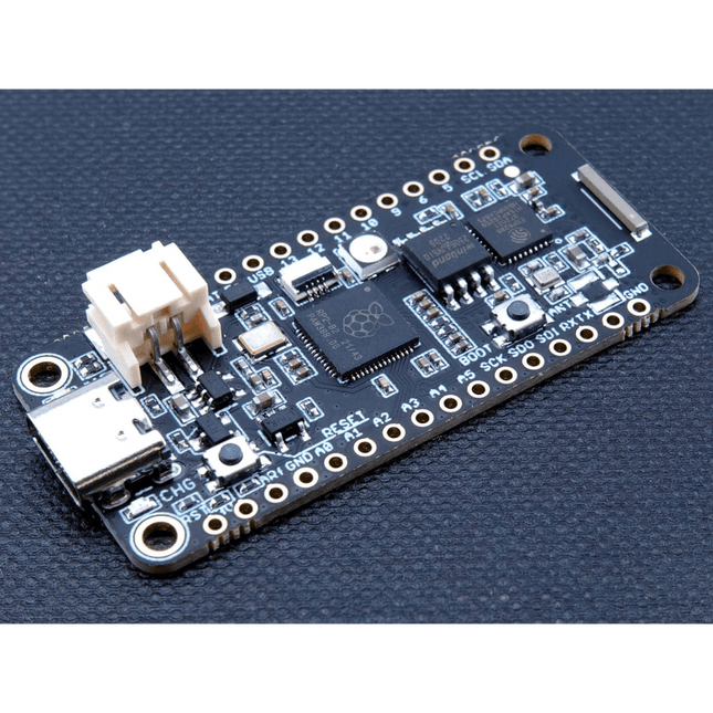
iLabs iLabs Challenger RP2040 WiFi/BLE MkII with Chip Antenna
The Challenger RP2040 WiFi is a small embedded computer equipped with a WiFi module, in the popular Adafruit Feather form factor. It is based on an RP2040 microcontroller chip from the Raspberry Pi Foundation which is a dual-core Cortex-M0 that can run on a clock up to 133 MHz. The RP2040 is paired with a 8 MB high-speed flash capable of supplying data up to the max speed. The flash memory can be used both to store instructions for the microcontroller as well as data in a file system and having a file system available makes it easy to store data in a structured and easy to program approach. The device can be powered from a Lithium Polymer battery connected through a standard 2.0 mm connector on the side of the board. An internal battery charging circuit allows you to charge your battery safely and quickly. The device is shipped with a programming resistor that sets the charging current to 250 mA. This resistor can be exchanged by the user to either increase or decrease the charging current, depending on the battery that is being used. The WiFi section on this board is based on the Espressif ESP8285 chip which basically is a ESP8266 with 1 MB flash memory integrated onto the chip making it a complete WiFi only requiring very few external components. The ESP8285 is connected to the microcontroller using a UART channel and the operation is controlled using a set of standardized AT-commands. Specifications Microcontroller RP2040 from Raspberry Pi (133 MHz dual-core Cortex-M0) SPI One SPI channel configured I²C One I²C channel configured UART One UART channel configured (second UART is for the WiFi chip) Analog inputs 4 analog input channels WLAN controller ESP8285 from Espressif (160 MHz single-core Tensilica L106) Flash memory 8 MByte, 133 MHz SRAM memory 264 KByte (divided into 6 banks) USB 2.0 controller Up to 12 MBit/s full speed (integrated USB 1.1 PHY) JST Battery connector 2.0 mm pitch Onboard LiPo charger 250 mA standard charge current Onboard NeoPixel LED RGB LED Dimensions 51 x 23 x 3,2 mm Weight 9 g Downloads Datasheet Design files Product errata
€ 17,95
Leden € 16,16
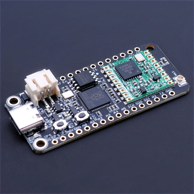
iLabs iLabs Challenger RP2040 LoRa (EU868)
The Challenger RP2040 LoRa is an Arduino/CircuitPython compatible Adafruit Feather format microcontroller board based on the Raspberry Pi Pico (RP2040) chip.The transceiver features a LoRa long range modem that provides ultra-long range spread spectrum communication and high interference immunity whilst minimizing current consumption.LoRaThe integrated module LoRa module (RFM95W) can achieve a sensitivity of over -148 dBm utilizing a low cost crystal and bill of materials. The high sensitivity combined with the integrated +20 dBm power amplifier yields industry leading link budget making it optimal for any application requiring range or robustness. LoRa also provides significant advantages in both blocking and selectivity over conventional modulation techniques, solving the traditional design compromise between range, interference immunity and energy consumption.The RFM95W is connected to the RP2040 via SPI channel 1 and a few GPIO’s that is required for signaling. A U.FL connector is used to attach your LoRa antenna to the board. 168 dB maximum link budget +20 dBm – 100 mW constant RF output vs. V supply +14 dBm high efficiency PA Programmable bit rate up to 300 kbps High sensitivity: down to -148 dBm Bullet-proof front end: IIP3 = -12.5 dBm Excellent blocking immunity Low RX current of 10.3 mA, 200 nA register retention Fully integrated synthesizer with a resolution of 61 Hz FSK, GFSK, MSK, GMSK, LoRaTM and OOK modulation Built-in bit synchronizer for clock recovery Preamble detection 127 dB Dynamic Range RSSI Automatic RF Sense and CAD with ultra-fast AFC Packet engine up to 256 bytes with CRC Specifications Microcontroller RP2040 from Raspberry Pi (133 MHz dual-core Cortex-M0) SPI Two SPI channels configured (second SPI connected to RFM95W) I²C One I²C channel configured UART One UART channel configured Analog inputs 4 analog input channels Radio module RFM95W from Hope RF Flash memory 8 MB, 133 MHz SRAM memory 264 KB (divided into 6 banks) USB 2.0 controller Up to 12 MBit/s full speed (integrated USB 1.1 PHY) JST Battery connector 2.0 mm pitch On board LiPo charger 450 mA standard charge current Dimensions 51 x 23 x 3,2 mm Weight 9 g Downloads Datasheet Design files
€ 24,95
Leden € 22,46


-
, van Saad Imtiaz SparkFun Thing Plus Matter (MGM240P): Een veelzijdig Matter gebaseerd IoT Ontwikkelboard (Review)
De SparkFun Thing Plus Matter - MGM240P is a veelzijdig ontwikkelboard dat rijk is aan features en ontworpen is voor het ontwikkelen van Matter-gebaseerde IoT...
